Table of Contents
Advertisement
Quick Links
Advertisement
Table of Contents

Related Manuals for DFI CS350-C246


Summary of Contents for DFI CS350-C246
- Page 1 CS350-C246/Q370 MicroATX Industrial Motherboard User’s Manual A-572-M-2032...
- Page 2 Copyright FCC and DOC Statement on Class B This publication contains information that is protected by copyright. No part of it may be This equipment has been tested and found to comply with the limits for a Class B digital reproduced in any form or by any means or used to make any transformation/adaptation device, pursuant to Part 15 of the FCC rules.
-
Page 3: Table Of Contents
Overview ..........................32 Main ............................33 Chapter 1 - Introduction........................ 6 Advanced ..........................33 Specifications ......................... 6 RC ACPI Configuration ....................34 CS350-C246 ........................6 CPU Configuration ......................34 CS350-Q370 ........................7 Power & Performance ....................35 PCH-FW Configuration ....................35 Features ..........................8 Trusted Computing ......................38 Chapter 2 - Hardware Installation .................... - Page 4 About this Manual Static Electricity Precautions This manual can be downloaded from the website. The manual is subject to change and It is quite easy to inadvertently damage your PC, system board, components or devices even update without notice, and may be based on editions that do not resemble your actual before installing them in your system unit.
- Page 5 Before Using the System Board • One CS350-C246/CS350-Q370 board • One COM port cable (Length: 300mm, 2 x DB9 ports) When installing the system board in a new system, you will need at least the following internal components.
-
Page 6: Chapter 1 - Introduction
1 x M.2 2230 E key (PCIe x2/USB2.0/intel CNVi support) X Specifications 1 x M.2 2242/2260/2280 M key (PCIe Gen3 x 4 NVMe) AUDIO Audio Codec Realtek ALC888 CS350-C246 ETHERNET Controller 1 x Intel® i219LM PCIe (10/100/1000Mbps) 1 x Intel® i211AT PCIe (10/100/1000Mbps) with iAMT 12.0 (only Xeon, SYSTEM Processor Intel®... -
Page 7: Cs350-Q370
Chapter 1 INTRODUCTION Specifications REAR I/O Ethernet 2 x GbE (RJ-45) 2 x USB 3.1 Gen 2 CS350-Q370 2 x USB 2.0 SYSTEM Processor Intel LGA 1151 Socket Processors ® 2 x USB 3.1 Gen 1 8th Generation:: Serial 1 x RS-232/422/485 (RS-232 w/ power) (DB-9) - Core™... -
Page 8: Features
Chapter 1 INTRODUCTION Wake-On-USB X Features This function allows you to use a USB keyboard or USB mouse to wake up a system from the Watchdog Timer S3 (STR - Suspend To RAM) state. The Watchdog Timer function allows your application to regularly “clear” the system at the set time interval. -
Page 9: Chapter 2 - Hardware Installation
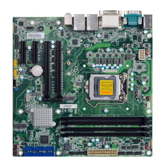
Chapter 2 HARDWARE INSTALLATION Chapter 2 - Hardware Installation Note: Some components are optional and only available upon request. X Board Layout Important: DDR4_3 DDR4_4 Electrostatic discharge (ESD) can damage your board, processor, KB/MS SYS FAN1 USB 5/6 disk drives, add-in boards, and other components. Perform (USB 2.0) CPU FAN1 JP10... -
Page 10: System Memory
Dual Channel DIMMs of the same memory configuration are on different channels. Step 1 Features • CS350-C246: Four 288-pin ECC/Non-ECC DIMM up to 64GB • CS350-Q370: Four 288-pin Non-ECC DIMM up to 64GB • Dual Channel DDR4 2400/2666 MHz User's Manual | CS350... -
Page 11: Removing The Dimm Module
Chapter 2 HARDWARE INSTALLATION System Memory Installing the DIMM Module System Memory Removing the DIMM Module Please follow the steps below to install the memory card into the socket. Please follow the steps below to remove the memory card from the socket. Step 1: Step 1: Press the eject tabs at both ends of the socket outward and downward to release them from... -
Page 12: Cpu
Chapter 2 HARDWARE INSTALLATION X CPU Installing the CPU 1. Make sure the PC and all other peripheral devices connected to it have been powered down. The system board is equipped with a surface mount LGA 1151 socket. This socket is exclusively designed for installing a LGA 1151 packaged Intel CPU. - Page 13 Chapter 2 HARDWARE INSTALLATION Installing the CPU Installing the CPU Load lever 7-2. T w o k e y s o n t h e 5. Lift the load lever and the load plate all the way up as shown in socket and notches on Alignment key the CPU also facilitate...
-
Page 14: Installing The Fan And Heat Sink
Chapter 2 HARDWARE INSTALLATION Installing the Fan and Heat Sink 4. Screw tight two of the spring screws at opposite corners into the mounting holes. And The CPU must be kept cool by using a CPU fan with heat sink. Without sufficient air circulation then proceed with the other two spring screws. -
Page 15: Jumper Settings
2280 2260 2242 SPI Flash BIOS DDR4_1 DDR4_2 Chapter 2 SMBus HARDWARE INSTALLATION PCIE1 (PCIe x16) PCIE2 (PCIe x16) SATA4/5 COM 1 Serial Mode X Jumper Settings (left/right) Intel Buzzer Clear CMOS SATA2/3 PCIE3 (PCIe x4) C246/Q370 (left/right) Battery USB 3.1 Gen 2 (USB 5/6) „... -
Page 16: Com 2 Serial Mode
Chapter 2 HARDWARE INSTALLATION Jumper Settings Jumper Settings COM 2 Serial Mode COM1 & COM2 RS232 Power Select JP6 (left) JP10 JP8 (right) JP4 (right) JP7 (right) „ COM 2 JP6, JP8, and JP10 are used to configure the COM 2 port to RS232, RS422 (Full Duplex) or RS485. -
Page 17: Digital I/O (Dio) Power Select
Line Out Line In Note Chapter 2 2280 2260 2242 SPI Flash BIOS DDR4_1 DDR4_2 HARDWARE INSTALLATION SMBus PCIE1 (PCIe x16) Jumper Settings PCIE2 (PCIe x16) SATA4/5 Digital I/O (DIO) Power Select (left/right) Intel Buzzer SATA2/3 PCIE3 (PCIe x4) C246/Q370 (left/right) Battery USB 3.1 Gen 2... -
Page 18: Rear I/O Ports
Chapter 2 HARDWARE INSTALLATION X Rear I/O Ports Rear I/O Ports PS/2 Keyboard/Mouse „ PS/2 KB/MS „ COM „ LAN 1 „ LAN 2 „ Audio „ DVI-I „ PS/2 KB/MS „ 2 x USB 2.0 „ DP++ „ 2 x USB „... -
Page 19: Usb Ports
Chapter 2 HARDWARE INSTALLATION Rear I/O Ports Rear I/O Ports USB Ports Graphics Display „ USB 6 (USB 2.0) „ USB 5 (USB 2.0) „ DP++ „ DVI-I (DVI-D Signal) „ HDMI DisplayPort ++ „ USB 2 (USB 3.1 Gen 1) „... -
Page 20: Rj45 Lan
Chapter 2 HARDWARE INSTALLATION Rear I/O Ports Rear I/O Ports RJ45 LAN Audio „ LAN 1 „ LAN 2 „ Line-out „ Mic-in The two LAN ports allow the system board to connect to a local area network. The system board is equipped with three rear audio jacks: BIOS Setting •... -
Page 21: Com 1 (Serial) Port
Chapter 2 HARDWARE INSTALLATION Rear I/O Ports COM 1 (Serial) Port „ COM 1 „ COM 1 Pin Assignment Standard RS232 RS422 RS485 RS232 with Power DCD- +12V TXD- Data- TXD+ Data+ RXD+ N.C. DTR- DTR- RXD- N.C. DSR- DSR- N.C. -
Page 22: Internal I/O Connectors
Chapter 2 HARDWARE INSTALLATION X Internal I/O Connectors COM (Serial) Port DDR4_3 DDR4_4 „ COM Port Pin Assignment CPU FAN1 JP10 Standard RS232 with RS422 RS485 RS232 Power (COM 2) (COM 2) (COM 2) „ COM 2/3/4 from top to bottom DCD- +12V TXD-... -
Page 23: Usb Ports
Standby Chapter 2 Power HARDWARE INSTALLATION B 1/2 B 3.1 Gen 1) Internal I/O Connectors USB Ports The USB device allows data exchange between your computer and a wide range of simultaneously accessible external Plug and Play peripherals. Front B 3/4 Panel B 3.1 Gen 2) In addition to the rear USB ports as introduced previously in this chapter, the system board... -
Page 24: Front Audio
LAN2 Front USB 3/4 Panel Chapter 2 (USB 3.1 Gen 2) HARDWARE INSTALLATION LAN LED M.2 M Key Internal I/O Connectors Internal I/O Connectors Mic In Line Out Front Audio SATA (Serial ATA) Line In Note 2280 2260 2242 SPI Flash BIOS DDR4_1 DDR4_2 SMBus... -
Page 25: Digital I/O
Chapter 2 HARDWARE INSTALLATION Internal I/O Connectors Internal I/O Connectors Digital I/O Cooling Fan Connectors System Fan 1 (left), CPU Fan (right) „ System Fan 1/2/3 „ Digital I/O „ CPU Fan (PWM) System Fan 2 (right) System Fan 3 (left) The 8-bit Digital I/O (DIO) connector allows for input/output signals of digital logical states defined by voltage levels. -
Page 26: Power Connector
Line Out Line In Note 2280 2260 2242 Chapter 2 SPI Flash BIOS DDR4_1 DDR4_2 HARDWARE INSTALLATION SMBus Internal I/O Connectors Internal I/O Connectors PCIE1 (PCIe x16) Power Connector Chassis Intrusion PCIE2 (PCIe x16) SATA4/5 (left/right) Intel Buzzer „ ATX 24-pin Power SATA2/3 Connector PCIE3 (PCIe x4) -
Page 27: Front Panel
Chapter 2 HARDWARE INSTALLATION Internal I/O Connectors Internal I/O Connectors Front Panel S/PDIF PWR-LED HD-LED RESET ATX-SW 11 12 „ Front Panel Connector „ S/PDIF Connector „ Front Panel Pin Assignment Assignment Assignment N.C. LED Power HDD Power PWR-LED LED Power HD-LED The Sony/Philips Digital Interface (S/PDIF) connector is for audio output to external audio Signal... -
Page 28: Battery
Chapter 2 HARDWARE INSTALLATION Internal I/O Connectors Internal I/O Connectors Battery SMBus „ SMBus „ Battery Holder The lithium ion battery addendum supplies power to the real-time clock and CMOS memory The SMBus (System Management Bus) connector is used to connect the SMBus device. It is a as an auxiliary source of power when the main power is shut off. -
Page 29: Lan Led
Chapter 2 HARDWARE INSTALLATION Internal I/O Connectors Internal I/O Connectors LAN LED Expansion Slots M.2 M Key „ LAN LED Connector M.2 E Key The LAN LED connector is used to detect the connection state of RJ45 LAN ports when M.2 Sockets the connection is made to an active network via a cable. -
Page 30: Installing The M.2 Module
Chapter 2 HARDWARE INSTALLATION Internal I/O Connectors Expansion Slots Installing the M.2 Module Before installing the M.2 module into the M.2 socket, please make sure that the following Please follow the steps below to install the card into the socket. safety cautions are well-attended. -
Page 31: Lpc
Chapter 2 HARDWARE INSTALLATION Internal I/O Connectors The LPC connector is used for debugging. „ LPC Connector „ LPC Pin Assignment Pin Assignment Pin Assignment L_CLK L_LAD1 L_RST# L_LAD0 L_FRAME# 3.3V L_LAD3 L_LAD2 SERIRQ 5VSB User's Manual | CS350... -
Page 32: Chapter 3 - Bios Settings
Chapter 3 BIOS SETTINGS Chapter 3 - BIOS Settings Legends X Overview Keys Function The BIOS is a program that takes care of the basic level of communication between the CPU and peripherals. It contains codes for various advanced features found in this system board. Right / Left arrow Move the highlight left or right to select a menu The BIOS allows you to configure the system and save the configuration in a battery-backed... -
Page 33: Main
Chapter 3 BIOS SETTINGS X Main X Advanced The Main menu is the first screen that you will see when you enter the BIOS Setup Utility. The Advanced menu allows you to configure your system for basic operation. Some entries are defaults required by the system board, while others, if enabled, will improve the performance of your system or let you set some features according to your preference. -
Page 34: Rc Acpi Configuration
Chapter 3 BIOS SETTINGS Advanced Advanced RC ACPI Configuration CPU Configuration Wake system from S5 Intel (VMX) Virtualization Technology When Enabled, the system will automatically power up at a designated time every day. Once When this field is set to Enabled, the VMM can utilize the additional hardware capabilities it’s switched to [Enabled], please set up the time of day including hour, minute, and second provided by Vanderpool Technology. -
Page 35: Power & Performance
Chapter 3 BIOS SETTINGS Advanced Advanced Power & Performance PCH-FW Configuration Intel(R) SpeedStep(tm) ME State This field is used to enable or disable the Intel SpeedStep Technology, which helps optimize When this field is set to Disabled, ME will be put into ME Temporarily Disabled Mode. ®... - Page 36 Chapter 3 BIOS SETTINGS Advanced PCH-FW Configuration Advanced PCH-FW Configuration ► AMT Configuration ► AMT Configuration ► Secure Erase Configuration USB Provisioning of AMT Secure Erase Mode Enable or disable AMT USB Provisioning. Select Secure Erase module behavior: Simulated or Real. Force Secure Erase Enable or disable Force Secure Erase on next boot.
- Page 37 Chapter 3 BIOS SETTINGS Advanced PCH-FW Configuration Advanced PCH-FW Configuration ► AMT Configuration ► OEM Flags Settings ► Firmware Update Configuration Hide Unconfigure ME Confirmation Prompt Me FW Image Re-Flash Enable or disable to hide unconfigure ME confirmation prompt when attempting ME This field is used to enable or disable the ME FW Image Re-Flash function, which allows the unconfiguration.
-
Page 38: Trusted Computing
Chapter 3 BIOS SETTINGS Advanced Advanced Trusted Computing NCT6116D Super IO Configuration Security Device Support WatchDog Timer Unit This field is used to enable or disable BIOS support for the security device such as an TPM 2.0 Select WatchDog Timer Unit — Second or Minute. to achieve hardware-level security via cryptographic keys. -
Page 39: Nct6116D Hw Monitor
Chapter 3 BIOS SETTINGS Advanced NCT6116D Super IO Configuration Advanced ► Serial Port 1/2/3/4 Configuration NCT6116D HW Monitor This section displays the system’s health information, i.e. voltage readings, CPU and system Serial Port temperatures, and fan speed readings. Enable or disable the current serial COM port. RS485 Auto Flow Enable or disable RS485 auto flow. -
Page 40: Serial Port Console Redirection
Chapter 3 BIOS SETTINGS Advanced NCT6116D HW Monitor Advanced ► Smart Fan Function Serial Port Console Redirection Smart Fan is a fan speed moderation strategy dependent on the current system temperature. Console Redirection When the system temperature goes higher than the Boundary setting, the fan speed will be turned up to the setting of the Fan Speed Count that bears the same index as the Boundary By enabling Console Redirection of a COM port, the sub-menu of console redirection settings field. -
Page 41: Usb Configuration
Chapter 3 BIOS SETTINGS Advanced Serial Port Console Redirection Advanced ► Console Redirection Settings USB Configuration Configure the serial settings of the current COM port. Legacy USB Support Terminal Type Enabled Enable Legacy USB support. Select terminal type: VT100, VT100+, VT-UTF8 or ANSI. Disabled Keep USB devices available only for EFI applications. -
Page 42: Network Stack Configuration
Chapter 3 BIOS SETTINGS Advanced Advanced Network Stack Configuration CSM Configuration CSM Support Network Stack This section is used to enable or disable CSM Support. The following fields are only available Enable or disable UEFI network stack. The following fields will appear when this field is when "CSM Support"... -
Page 43: Usb Power Control
Chapter 3 BIOS SETTINGS Advanced Advanced X USB Power Control USB Power Control USB Power Control To control USB Power Parameters. This page provides options of the USB power type. 5V_Dual USB keyboard and mouse can wake up the system from S3/S4 mode. USB keyboard and mouse can't wake up the system from S3/S4 mode. -
Page 44: Chipset
Chapter 3 BIOS SETTINGS X Chipset Chipset Graphics Configuration To configure relevant graphics settings. Primary Display Select which of IGFX/PEG/PCI Graphics device to be the primary display. Internal Graphics Keep IGFX enabled based on the setup options. User's Manual | CS350... -
Page 45: Peg Port Configuration
Chapter 3 BIOS SETTINGS Chipset Chipset PEG Port Configuration PCH-IO Configuration Enable Root Port LAN1(I219) Enable or disable the root port. Enable or disable onboard NIC. Max Link Speed Wake on LAN Enable Configure PCIE1/PCIE2 port’s Max Speed: Auto, Gen1, Gen2 or Gen3. Enable or disable integrated LAN to wake the system. -
Page 46: Sata And Rst Configuration
Chapter 3 BIOS SETTINGS Advanced Chipset PCH-IO Configuration SATA And RST Configuration PCI Express Configuration Select one of the PCI Express channels and press enter to configure the following settings. SATA Controller(s) PCIE3/PCIE4/M.2-E/M.2-M/LAN2 This field is used to enable or disable the Serial ATA controller. Enable or disable the PCI Express Root Port. -
Page 47: Hd Audio Configuration
Chapter 3 BIOS SETTINGS Chipset PCH-IO Configuration HD Audio Configuration HD Audio Control the detection of the HD Audio device. Disabled HDA will be unconditionally disabled. Enabled HDA will be unconditionally enabled. User's Manual | CS350... -
Page 48: Security
Chapter 3 BIOS SETTINGS X Security Security Secure Boot Administrator Password Secure Boot Set the administrator password. To clear the password, input nothing and press enter when a The Secure Boot store a database of certificates in the firmware and only allows the OSes with authorized signatures to boot on the system. - Page 49 Chapter 3 BIOS SETTINGS Security Secure Boot X Key Management • “PK” for Platform Keys • “KEK” for Key Exchange Keys • “db” for Authorized Signatures • “dbx” for Forbidden Signatures Enroll Efi Image Allow the image to run in Secure Boot mode. Enroll SHA256 Hash certificate of a PE image into Authorized Signature Database (db).
-
Page 50: Boot
Chapter 3 BIOS SETTINGS X Boot X Save & Exit Setup Prompt Timeout Save Changes and Reset Set the number of seconds to wait for the setup activation key. 65535 (0xFFFF) denotes To save the changes, select this field and then press <Enter>. A dialog box will appear. Select indefinite waiting. -
Page 51: Updating The Bios
BIOS with the flash utility. For updating AMI BIOS in UEFI mode, you may refer to the how-to video at https://www.dfi.com/Knowledge/Video/5. X Notice: BIOS SPI ROM 1. -
Page 52: Chapter 4 - Intel Amt Settings
Chapter 4 INTEL AMT SETTINGS Chapter 4 - Intel AMT Settings X Enable Intel AMT in the AMI BIOS ® X Overview 1. Power-on the system then press <Del> to enter the main menu of the AMI BIOS. 2. In the Advanced menu, select PCH-FW Configuration. Intel Active Management Technology (Intel AMT) combines hardware and software solution to ®... -
Page 53: Entering Management Engine Bios Extension (Mebx)
Chapter 4 INTEL AMT SETTINGS Enable Intel AMT in the AMI BIOS X Entering Management Engine BIOS Extension (MEBX) ® 4. Press F4, or go to the Save & Exit menu, select Save Changes and Reset and then press <Enter>. A dialog box will appear. Select Yes and press Enter to reset the system after saving all changes made. -
Page 54: Mebx
Chapter 4 INTEL AMT SETTINGS X MEBX Intel(R) ME General Settings Main Menu Select Intel(R) ME General Settings under Main Menu and then press Enter. Select MEBx Login under Main Menu and press Enter. A prompt that requires password input will show up. - Page 55 Chapter 4 INTEL AMT SETTINGS MEBX Intel(R) ME General Settings MEBX Intel(R) ME General Settings Change ME Password Local FW Update If you want to change ME password, select Change ME Password and then press Enter. A Select Local FW Update then press Enter. Select Enabled or Disabled or Password Protected prompt that requires password input will show up.
-
Page 56: Intel(R) Standard Manageability
Chapter 4 INTEL AMT SETTINGS MEBX Intel(R) Standard Manageability > SOL/Storage Redirection/KVM Enable Intel(R) Standard Manageability under Main Menu to show relevant options. Press Enter to enter the submenu. Manageability Feature Selection Select Enabled or Disabled then press Enter. When disabled, all the following fields will be hidden. - Page 57 Chapter 4 INTEL AMT SETTINGS MEBX Intel(R) Standard Manageability Configuration MEBX Intel(R) Standard Manageability Configuration > SOL/Storage Redirection/KVM > User Consent Move the cursor to select a field and press Enter to display options. Press Enter to enter the submenu. Select Enabled or Disabled then press Enter.
- Page 58 Chapter 4 INTEL AMT SETTINGS MEBX Intel(R) Standard Manageability Configuration MEBX Intel(R) Standard Manageability Configuration > User Consent Password Policy Move the cursor to select a field and press Enter to display options. Under the Intel(R) Standard Manageability Configuration menu, select Password Policy then press Enter.
- Page 59 Chapter 4 INTEL AMT SETTINGS MEBX Intel(R) Standard Manageability Configuration > Network Setup Move the cursor to select a field and press Enter to display options. Under the Intel(R) Standard Manageability Configuration menu, select Network Setup and then press Enter. Host Name Enter the computer’s host name and then press Enter.
- Page 60 Chapter 4 INTEL AMT SETTINGS MEBX Intel(R) Standard Manageability Configuration Network Setup MEBX Intel(R) Standard Manageability Configuration Network Setup Intel(R) ME Network Name Settings > TCP/IP Settings DHCP Mode Under the Intel(R) ME Network Setup menu, select TCP/IP Settings and then press Enter. Select Enabled or Disabled then press Enter.
- Page 61 Chapter 4 INTEL AMT SETTINGS MEBX Intel(R) Standard Manageability Configuration Network Setup Activate Network Access TCP/IP Settings Select Activate Network Access and press Enter, and then press Y to activate the ME network connection with the settings configured previously, or press N to abort. IPv4 Address Assign a valid and available IP address to the system.
- Page 62 Chapter 4 INTEL AMT SETTINGS MEBX Intel(R) Standard Manageability Configuration > Remote Setup And Configuration Under the Intel(R) Standard Manageability Configuration menu, select Remote Setup And Current Provisioning Mode Configuration then press Enter. The current mode — Public Key Infrastructure (PKI) — is displayed. Provisioning Record Press Enter to view the record.
- Page 63 Chapter 4 INTEL AMT SETTINGS MEBX Intel(R) Standard Manageability Configuration Remote Setup And Configuration MEBX Intel(R) Standard Manageability Configuration Remote Setup And Configuration > RCFG > TLS PKI Press Enter, select Start Configuration, and then press Enter to activate Remote Configuration The system adopts PKI for encryption and authentication, and the TLS protocol for (RCFG).
- Page 64 Chapter 4 INTEL AMT SETTINGS MEBX Intel(R) Standard Manageability Configuration Remote Setup And Configuration MEBX Intel(R) Standard Manageability Configuration TLS PKI > Power Control Under the Intel(R) Standard Manageability Configuration menu, select Power Control then > Manage Hashes press Enter. Select a hash name and then press the following keys to execute a function.
- Page 65 Chapter 4 INTEL AMT SETTINGS MEBX MEBx Exit Under the Main Menu, select MEBx Exit and then press Enter. Press Y to confirm or N to abort. User's Manual | CS350...
-
Page 66: Chapter 5 - Raid
Chapter 5 RAID Chapter 5 - RAID X Setup Procedure The system board allows configuring RAID on Serial ATA drives. It supports RAID 0, RAID 1, RAID 5 and RAID 10. To enable the RAID function, the following settings are required. X RAID Levels 1. - Page 67 Chapter 5 RAID Step 3: Create a RAID Volume Step 4: Install the Intel Rapid Storage Technology Utility 1. Go to the “Advanced” menu of the AMI BIOS and select “Intel(R) Rapid Storage The Intel Rapid Storage Technology Utility can be installed from within Windows. It allows RAID Technology”.
Need help?
Do you have a question about the CS350-C246 and is the answer not in the manual?
Questions and answers