
Subscribe to Our Youtube Channel
Related Manuals for DFI CS332-C246/Q370


Summary of Contents for DFI CS332-C246/Q370
- Page 1 CS332-C246/Q370 MicroATX Industrial Motherboard User’s Manual © February 02, 2024 DFI Inc.
- Page 2 1. The changes or modifications not expressly approved by the party responsible for com- are the properties of the respective owners. pliance could void the user’s authority to operate the equipment. 2. Shielded interface cables must be used in order to comply with the emission limits. User's Manual | CS332-C246/Q370...
-
Page 3: Table Of Contents
Serial Port Console Redirection ...................33 Serial Port Console Redirection ► Console Redirection Settings ......33 Serial Port Console Redirection ► Console Redirection Settings ......34 USB Configuration ......................35 CSM Configuration ......................35 USB Power Control ......................36 Network Stack Configuration..................36 User's Manual | CS332-C246/Q370... - Page 4 • To reduce the risk of electric shock, unplug the power cord before removing the sys- tem chassis cover for installation or servicing. After installation or servicing, cover the system chassis before plugging the power cord. User's Manual | CS332-C246/Q370...
- Page 5 The board and accessories in the package may not come similar to the information listed above. This may differ in accordance with the sales region or models in which it was sold. For more information about the standard package in your region, please contact your dealer or sales repre- sentative. User's Manual | CS332-C246/Q370...
-
Page 6: Chapter 1 - Introduction
2 x PCIe x4 (Gen 3) 1 x PCI 1 x MINI PCIE SLOT (Full Size) 1 x M.2 2242/2280 M key (PCIe Gen3 x 4 NVMe/Intel Optane Memory Support) 1 x M.2 2230 E key (PCIe x1/USB2.0) User's Manual | CS332-C246/Q370... - Page 7 Typical: i7-8700K: 3.3V @ 0.44A (1.452Watt); 5V @ 0.62A (3.1Watt); 12V @ 0.49A (5.88Watt) Max.: i7-8700K:3.3V @ 0.51A (1.683Watt); 5V @ 1.4A (7.0Watt); 12V @ 10.44A (128.25Watt) RTC Battery CR2032 Coin Cell OS SUPPORT Windows 10 IoT Enterprise 64-bit Linux User's Manual | CS332-C246/Q370...
- Page 8 [Q370] 596,170 hrs @ 25°C; 341,995 hrs @ 45°C ; 213,835 hrs @ 60°C ; 182,033 hrs @ 65°C Calculation Model: Telcordia Issue 4 Environment: GB, GC - Ground Benign, Controlled MECHANISM Dimensions microATX Form Factor: 244mm (9.6") x 244mm (9.6") Height PCB: 1.6mm Top Side: 38.5mm, Bottom Side: 4.4mm User's Manual | CS332-C246/Q370...
-
Page 9: Block Diagram
Chapter 1 INTRODUCTION X Block Diagram X Dimension CS332-C246 CS332-Q370 User's Manual | CS332-C246/Q370... -
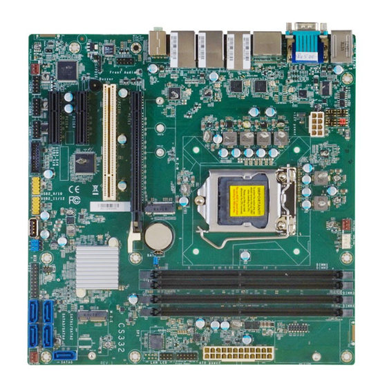
Page 10: Chapter 2 - Hardware Installation
▲COM1 SATA1 (R1) ▼VGA ▲PS/2 KB/MS SATA2 (R2) ▼USB 2.0 Clear CMOS M.2 E Key HSIO Signal Trace Selection SATA3 (R1) Mini PCIe/mSATA select SATA4 (R1) System Fan2 DIMM1 DIMM2 SATA0 (R5) PCIE3 DIMM3 PCIE2 DIMM4 User's Manual | CS332-C246/Q370... - Page 11 LAN 3/4 LED LAN 1/2 LED Front Panel ATX Power +12V Power COM 1 Serial Mode (JP2) COM 1 Serial Mode (JP1) COM 1 RS232 Power Select COM 1 Serial Mode (JP3) System Fan1 CPU Fan User's Manual | CS332-C246/Q370...
-
Page 12: Installing The Heat Sink
3. Screw tight two of the spring screws at opposite corners into the mounting holes. And then proceed with the other two spring screws. 10 11 M.2 M Key Battery M.2 E Key Mounting holes User's Manual | CS332-C246/Q370... -
Page 13: Jumper Settings
M.2 M Key M.2 M Key Battery Battery JP19 JP18 M.2 E Key M.2 E Key „ 2-3 On: GND „ 2-3 On: +5V „ 1-2 On: DIO power used (default) „ 1-2 On: +5VDU (default) User's Manual | CS332-C246/Q370... -
Page 14: Com 1 Serial Mode (Jp1, Jp2, Jp3)
„ 3-5, 4-6 On „ 3-5, 2-4 On JP1 & JP2 „ 1-3 On: Pin 9 = RI- „ 3-5 On: Pin 9 = +5V „ 1-3, 2-4 On „ 3-5, 4-6 On „ 3-5, 4-6 On User's Manual | CS332-C246/Q370... -
Page 15: Clear Cmos (Jp5)
10 11 M.2 M Key M.2 M Key Battery Battery M.2 E Key M.2 E Key „ 1-2 On: Normal (default) „ 2-3 On: Clear CMOS „ 1-2 On: To CN10 (default) „ 2-3 On: To J20 User's Manual | CS332-C246/Q370... -
Page 16: Mini Pcie/Msata Select (Jp9)
Chapter 2 HARDWARE INSTALLATION Mini PCIe/mSATA Select (JP9) 10 11 M.2 M Key Battery M.2 E Key „ 1-2 On: Mini PCIe (default) „ 2-3 On: mSATA User's Manual | CS332-C246/Q370... -
Page 17: Pin Assignment
10 11 10 11 M.2 M Key M.2 M Key Battery Battery M.2 E Key M.2 E Key Assignment Pin Assignment LED Power HDD Power LED Power Assignment Assignment Signal Signal 3V3SB SMBus_Clock SMBus_DATA Signal Signal SMBus_Alert User's Manual | CS332-C246/Q370... -
Page 18: Chassis Intrusion (J14)
Digital I/O (J26) 10 11 10 11 M.2 M Key M.2 M Key Battery Battery M.2 E Key M.2 E Key Assignment Assignment +12V DIO_7 +12V Assignment DIO_6 DIO_5 Signal DIO_4 DIO_3 DIO_2 +5VDU DIO_1 +5VDU DIO_0 User's Manual | CS332-C246/Q370... -
Page 19: System Fan1/2/3 (J7 & J22 & J30 )
CPU FAN (J8) System Fan 3 10 11 10 11 M.2 M Key System Fan 1 M.2 M Key Battery Battery System Fan 2 M.2 E Key M.2 E Key Assignment Assignment Power TACH Sense Speed Control User's Manual | CS332-C246/Q370... -
Page 20: Sata0, 1, 2, 3, 4 (J28 & J23 & J17 & J25 & J27)
M.2 M Key Battery Battery SATA3 (R1) SATA1 (R1) M.2 E Key M.2 E Key SATA4 (R1) SATA2 (R2) SATA0 (R5) Assignment LAN 3/4 LED LAN 1/2 LED Assignment Assignment GBE(LAN1/3)_1000 GBE(LAN1/3)_100 GBE(LAN1/3)_LED_LINK_ACT 3V3DU LINK(LAN2/4)_1000 LINK(LAN2/4)_100 LINK(LAN2/4)_ACTIVITY 3V3DU User's Manual | CS332-C246/Q370... -
Page 21: Lpc (J21)
S/PDIF ( J1) 10 11 10 11 M.2 M Key M.2 M Key Battery Battery M.2 E Key M.2 E Key Assignment Assignment Assignment L_CLK L_LAD1 L_RST# L_LAD0 SPDIF Out L_FRAME# 3.3V L_LAD3 SPDIF In L_LAD2 SERIRQ 5VSB User's Manual | CS332-C246/Q370... -
Page 22: Front Audio ( J2)
Chapter 2 HARDWARE INSTALLATION Front Audio ( J2) 10 11 M.2 M Key Battery M.2 E Key Assignment Assignment Mic-L Mic-R N.C. Line-Out-R Mic-JD (sense) Line-Out-L Line-JD (sense) User's Manual | CS332-C246/Q370... -
Page 23: System Memory
DIMMs. Not all slots need to be populated. DIMM4 Dual Channel (DC) Data will be accessed in chunks of 128 bits from the memory channels. Dual channel provides better system performance because it doubles the data transfer rate. User's Manual | CS332-C246/Q370... -
Page 24: Expansion Slots
4. Make sure the notch on card is aligned to the key on the socket. 5. Make sure the standoff screw is removed from the standoff. M.2 M Key Battery M.2 Module M.2 Socket Stand-off M.2 E Key Notch M.2 M-Key M.2 E-Key User's Manual | CS332-C246/Q370... - Page 25 Screw tight the card onto the stand-off with a screw driver and a stand-off screw until the gap between the card and the stand-off closes up. The card should be lying parallel to the board when it’s correctly mounted. User's Manual | CS332-C246/Q370...
-
Page 26: Chapter 3 - Bios Settings
When “X” appears on the left of a particular field, it indicates that a submenu which contains additional options are available for that field. To display the submenu, move the highlight to that field and press <Enter>. User's Manual | CS332-C246/Q370... -
Page 27: Main
The time format is <hour>, <minute>, <second>. The time is based on the 24-hour military-time clock. For example, 1 p.m. is 13:00:00. Hour displays hours from 00 to 23. Minute displays min- utes from 00 to 59. Second displays seconds from 00 to 59. User's Manual | CS332-C246/Q370... -
Page 28: Rc Acpi Settings
The system automatically powers on after power failure. • S5 State The system enter soft-off state after power failure. Power-on signal input is required to power up the system. • Last State The system returns to the last state right before power failure. User's Manual | CS332-C246/Q370... -
Page 29: Power & Performance
MEBx Setup. This option does not disable manageability features in FW. AMT Configuration Configure Intel(R) Active Management Technology Parameters. ME Unconfig on RTC Clear When disabled, ME will not be unconfigured on RTC Clear. Firmware Update Configuration Configure Management Engine Technology Parameters. User's Manual | CS332-C246/Q370... -
Page 30: Trusted Computing
This field is used to enable or disable BIOS support for the security device such as an TPM 2.0 to achieve hardware-level security via cryptographic keys. SuperIO WatchDog Timer Set SuperIO WatchDog Timer Timeout value. The range is from 0 (disabled) to 255. User's Manual | CS332-C246/Q370... -
Page 31: Nct6116D Super Io Configuration ► Serial Port 1, 2 Configuration
Advanced Advanced NCT6116D Super IO Configuration NCT6116D Super IO Configuration ► Serial Port 1, 2 Configuration ► Serial Port 3, 4 Configuration Serial Port Serial Port Enable or disable serial port. Enable or disable serial port. User's Manual | CS332-C246/Q370... -
Page 32: Nct6116D Hw Monitor
Fan Speed Count 1 field. • Fan Speed Count 1 to Fan Speed Count 4 Set the fan speed, the value ranging from 1-100%, 100% being full speed. The fans will operate according to the specified boundary temperatures above-mentioned. User's Manual | CS332-C246/Q370... -
Page 33: Serial Port Console Redirection
Serial Port Console Redirection Serial Port Console Redirection ► Console Redirection Settings Console Redirection By enabling Console Redirection of a COM port, the sub-menu of console redirection settings will become available for configuration as detailed in the following. User's Manual | CS332-C246/Q370... -
Page 34: Serial Port Console Redirection ► Console Redirection Settings
Select parity bits: None, Even, Odd, Mark or Space. Stop Bits Select stop bits: 1 bit or 2 bits. Flow Control Select flow control type: None or Hardware RTS/CTS. Flow Control is for RS485 mode and is only supported by Serial Port 1 (COM1). User's Manual | CS332-C246/Q370... -
Page 35: Usb Configuration
Enable or disable USB Mass Storage Driver Support. Video This field controls the execution of UEFI and Legacy Video OpROM. Other PCI devices This field determines OpROM execution policy for devices other than Network, Storage or Video. User's Manual | CS332-C246/Q370... -
Page 36: Usb Power Control
Set the wait time in seconds to press ESC key to abort the PXE boot. Use either +/- or numeric keys to set the value. Media detect count Set the number of times the presence of media will be checked. Use either +/- or numeric keys to set the value. User's Manual | CS332-C246/Q370... -
Page 37: Chipset
Please select a submenu and press Enter. The submenus are detailed in the following pages. Primary Display Select which of IGFX/PEG/PCI Graphics device to be the primary display. Internal Graphics Keep IGFX "Enabled" or "Disabled" based on the setup options, or select "Auto" for auto-detec- tion. User's Manual | CS332-C246/Q370... -
Page 38: Peg Port Configuration
Assign the maximum value of Top Of Lower Usable DRAM (TOLUD). Select to specify a fixed value, or select "Dynamic" so that the assignment would adjust TOLUD automatically based on largest MMIO length of installed graphic controller. User's Manual | CS332-C246/Q370... -
Page 39: Pch-Io Configuration► Pci Express Configuration
The mode selection determines how the SATA controller(s) operates. • AHCI This option allows the Serial ATA controller(s) to use AHCI (Advanced Host Controller Interface). Ports and Hot Plug Enable or disable the Serial ATA port and its hot plug function. User's Manual | CS332-C246/Q370... -
Page 40: Pch-Io Configuration► Hd Audio Configuration
Chapter 3 BIOS SETTINGS Chipset PCH-IO Configuration ► HD Audio Configuration HD Audio Control the detection of the HD Audio device. • Disabled HDA will be unconditionally disabled. • Enabled HDA will be unconditionally enabled. User's Manual | CS332-C246/Q370... -
Page 41: Security
Secure Boot. Press Enter and a prompt will show up for you to confirm. Reset To Setup Mode Clear the database from the NVRAM, including all the keys and signatures installed in the Key Management menu. Press Enter and a prompt will show up for you to confirm. User's Manual | CS332-C246/Q370... -
Page 42: Boot
Refer to the Advanced > CSM Configuration submenu for more information. • Restore Setting from file This field will appear only when a USB flash device is detected. Select this field to restore setting from the USB flash device. User's Manual | CS332-C246/Q370... -
Page 43: Updating The Bios
MAC address should be burned or not. c. After updating unique MAC Address from manufacturing, NVM will be protected immediately after power cycle. Users cannot update NVM or MAC address. User's Manual | CS332-C246/Q370...
Need help?
Do you have a question about the CS332-C246/Q370 and is the answer not in the manual?
Questions and answers