
Related Manuals for DFI CS100 Series


Summary of Contents for DFI CS100 Series
- Page 1 CS100 Mini-ITX Industrial Motherboard User’s Manual Preliminary Version A50800839...
-
Page 2: Copyright
Copyright FCC and DOC Statement on Class B This publication contains information that is protected by copyright. No part of it may be re- This equipment has been tested and found to comply with the limits for a Class B digital produced in any form or by any means or used to make any transformation/adaptation without device, pursuant to Part 15 of the FCC rules. -
Page 3: Table Of Contents
Table of Contents SATA (Serial ATA) Connectors ..............23 Digital I/O Connector .................. 23 Digital I/O Power Connector ................ 23 Cooling Fan Connectors................24 Power Connectors ..................24 Copyright ......................2 LVDS LCD Panel Connector ................. 25 LCD/Inverter Power Connector ..............25 Trademarks Chassis Intrusion Connector ................ -
Page 4: Warranty
Warranty Static Electricity Precautions 1. Warranty does not cover damages or failures that arised from misuse of the product, in- It is quite easy to inadvertently damage your PC, system board, components or devices even ability to use the product, unauthorized replacement or alteration of components and prod- before installing them in your system unit. -
Page 5: About The Package
About the Package The package contains the following items. If any of these items are missing or damaged, please contact your dealer or sales representative for assistance. • One CS100-Q370/C246/H310 motherboard • One COM port cable (Length: 250mm, 1 x COM port) •... -
Page 6: Chapter 1 - Introduction
Chapter 1 Chapter 1 - Introduction Specifications SYSTEM Processor 8th Generation Intel ® Core™ Processors, LGA 1151 Socket, TDP up to 80W INTERNAL I/O Serial 1 x RS-232 (RS-232 w/ power) (2.0mm pitch) Intel ® Xeon E-2176G Processor Display 1 x LVDS LCD Panel Connector ®... -
Page 7: Features
Chapter 1 Features • Wake-On-LAN • Watchdog Timer This feature allows the network to remotely wake up a Soft Power Down (Soft-Off) PC. It is supported via the onboard LAN port or via a PCI LAN card that uses the PCI PME (Power Man- The Watchdog Timer function allows your application to regularly “clear”... - Page 8 Chapter 1 • Power Failure Recovery When power returns after an AC power failure, you may choose to either power-on the system manually or let the system power-on automatically. • USB The system board supports the new USB 3.1 Gen 2. It is capable of running at a maximum transmission speed of up to 10 Gbit/s (1.2 GB/s) and is faster than USB 3.1 Gen 1 (5 Gbit/s, or 625 MB/s), USB 2.0 (480 Mbit/s, or 60 MB/s) and USB 1.1 (12Mb/s).
-
Page 9: Chapter 2 - Hardware Installation
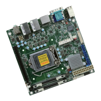
Chapter 2 Chapter 2 - Hardware Installation Important: Board Layout Electrostatic discharge (ESD) can damage your board, processor, disk drives, add-in boards, and other components. Perform installation procedures at an ESD workstation only. If such a station is not available, you can provide some ESD protection by wear- ing an antistatic wrist strap and attaching it to a metal part of the system chassis. -
Page 10: Installing The Sodimm Module
Chapter 2 The system board supports the following memory interface. Installing the SODIMM Module Note: Single Channel (SC) The system board used in the following illustrations may not resemble the actual Data will be accessed in chunks of 64 bits (8B) from the memory channels. board. -
Page 11: Cpu
Chapter 2 6. Grasping the module by its edges, position the module above the socket with the “notch” in the module aligned with the “key” on the socket. The keying mechanism ensures the module can be plugged into the socket in only one way. The system board is equipped with a surface mount LGA 1151 socket. -
Page 12: Installing The Cpu
Chapter 2 Load lever Installing the CPU 5. Lifting the load lever will at the same time lift the load plate. 1. Make sure the PC and all other peripheral devices connected to it has been powered down. Lift the load lever up to 2. - Page 13 Chapter 2 7. Insert the CPU into the 8. Close the load plate then socket. The gold triangular push the load lever down. mark on the CPU must align with the corner of While closing the load Retention knob the CPU socket shown on plate, make sure the front the photo.
-
Page 14: Installing The Fan And Heat Sink
Chapter 2 Installing the Fan and Heat Sink 4. Rotate each screw that are diagonally across the heat sink. Perform the same The CPU must be kept cool by using a CPU fan with heat sink. Without sufficient air circula- procedure for the other tion across the CPU and heat sink, the CPU will overheat damaging both the CPU and system board. -
Page 15: Jumper Settings
Chapter 2 Jumper Settings Backlight Brightness Select Clear CMOS 1-2 On: 1-2 On: +3.3V (default) Normal (default) 2-3 On: 2-3 On: Clear CMOS If you encounter the followings, JP7 is used to select the power level of backlight brightness control: +3.3V (default) or +5V. a) CMOS data becomes corrupted. -
Page 16: Com2 Rs232/Power Select
Chapter 2 COM 2 RS232/Power Select 5 3 1 5 3 1 6 4 2 6 4 2 1-3 (RI-), 2-4 (DCD-) On: 3-5 (+5V), 4-6 (+12V) On: RS232 (default) RS232 with power COM 2 COM 2 RS232 RS232 with power DCD- +12V SIN-... -
Page 17: Lcd/Inverter Power Select
Chapter 2 LCD/Inverter Power Select Panel Power Select 1-2 On: 1-2 On: +12V +12V (default) 2-3 On: 3-4 On: +5V 5-6 On: +3.3V (default) JP8 is used to select the power supplied with the LCD panel. JP9 is used to select the power level of LVDS LCD inverter connector. Important: Before powering-on the system, make sure that the power settings of JP8 match the LCD panel’s specification. -
Page 18: Mini Pcie/Msata Signal Select (Cs100-Q370/C246 Only)
Chapter 2 Mini PCIe/mSATA Signal Select (CS100-Q370/C246 only) 1-2 On: Mini PCIe (default) 2-3 On: mSATA JP2 is used to select the Mini PCIe signal. Chapter 2 Hardware Installation www.dfi .com... -
Page 19: Rear Panel I/O Ports
Chapter 2 Rear Panel I/O Ports COM 1 LAN 1 LAN 2 Line-in (optional) Line-out Mic-in DP++*2 USB 2.0*4 USB 3.1 Gen 1*4 CS100-H310 COM 1 LAN 1 LAN 2 Line-in (optional) Line-out Mic-in DP++*2 USB 2.0*4 USB 3.1 Gen 1*2 USB 3.1 Gen 2*2 CS100-Q370/C246 The rear panel I/O ports consist of the following:... -
Page 20: Rj45 Lan Ports
Chapter 2 RJ45 LAN Ports USB Ports USB 14 USB 9 USB 8 USB 7 USB 2.0 LAN 1 LAN 2 LAN 1 USB 4 USB 2 LAN 2 USB 3 USB 1 USB 3.1 Gen 1 USB 3.1 Gen 1 CS100-H310 USB 2 USB 4... -
Page 21: Graphics Interfaces
Chapter 2 Graphics Interfaces BIOS Setting Configure these onboard USB devices in the Advanced menu (“USB Configuration” submenu) The display ports consist of the following: of the BIOS. Refer to the chapter 3 for more information. • 1 VGA port Driver Installation •... -
Page 22: Com (Serial) Ports
Chapter 2 COM (Serial) Ports Audio 1 2 3 4 5 Line-in (optional) Line-out 6 7 8 9 Mic-in COM 1: RS232 Rear Audio COM 2: RS232 Front Audio Rear Audio COM 1 and COM 2 are fixed at RS232. The system board is equipped with 2 audio jacks (Line-out and Mic-in). -
Page 23: I/O Connectors
Chapter 2 I/O Connectors Digital I/O Connector Digital I/O Power Connector SATA (Serial ATA) Connectors SATA 3.0 6Gb/s SATA 2 SATA 1 SATA 0 Digital I/O Digital I/O Power +12V Ground 5VDU The 8-bit Digital I/O connector provides powering-on function to external devices that are con- Features nected to these connectors. -
Page 24: Cooling Fan Connectors
Chapter 2 Cooling Fan Connectors Power Connectors 12 24 +3.3V CTRL ATX power CPU Fan +12V +12V Ground +5VSB PWR_OK PS_ON# +3.3V -12V +3.3V +3.3V FAN IN +12V Power ystem Fan 1 Ground Ground +12V +12V Ground The fan connectors are used to connect cooling fans. The cooling fans will provide adequate airflow throughout the chassis to prevent overheating the CPU and system board components. -
Page 25: Lvds Lcd Panel Connector
Panel Power menu) of the BIOS. Refer to the chapter 3 for more information. Note: 1. LVDS LCD Panel Connector: DFI PN: 346-714000-201S Description: HEADER 40P/1.25mm, 180D, SMD, BEIGE, DF13E-40DP-1.25V(51)(Hirose)RoHS 2. LCD/Inverter Power Connector: DFI PN: 3346-510801-100G Description: BOX HEADER 1*8, 8P/2.0mm/180D, 721-81-08TW00(PINREX)RoHS Chapter 2 Hardware Installation www.dfi... -
Page 26: Chassis Intrusion Connector
Chapter 2 Chassis Intrusion Connector Front Panel Connector Front Chassis Panel Signal Intrusion Ground PWR-LED HD-LED ATX-SW RESET HD-LED - Hard Drive LED This LED will light when the hard drive is being accessed. The board supports the chassis intrusion detection function. Connect the chassis intrusion sensor cable from the chassis to this connector. -
Page 27: Expansion Slots
Chapter 2 Expansion Slots S/PDIF Connector Mini PCI Express & mSATA (CS100-Q370/CS246) mSATA (CS100-H310) PCI Express x16 S/PDIF Mini PCI Express Slot The S/PDIF connector is used to connect an external S/PDIF port. Your S/PDIF port may be The full-size Mini PCIe socket supports the installation of a Mini PCIe card or an mSATA card. mounted on a card-edge bracket. -
Page 28: Lpc Connector
LPC Connector Connecting the EXT-RS232/RS485 Card to the Motherboard With DFI’s proprietary technology, CS100-Q370/C246/H310 supports two extension modules for additional four COM ports. The EXT-RS232/RS485 card is connected to CS100-Q370/C246/H310 via the LPC connector. The illustrations below guide you how to connect the extension module to 14 13 the motherboard. -
Page 29: Battery
Chapter 2 Battery Battery Connector +3.3V Connect to the battery connector Battery The lithium ion battery powers the real-time clock and CMOS memory. It is an auxiliary source of power when the main power is shut off. Safety Measures • Danger of explosion if battery incorrectly replaced. •...
Need help?
Do you have a question about the CS100 Series and is the answer not in the manual?
Questions and answers