
Related Manuals for DFI CS350-C246


Summary of Contents for DFI CS350-C246
- Page 1 CS350-C246/Q370 MicroATX Industrial Motherboard User’s Manual Preliminary Preliminary Version Version A-572-M-2012...
- Page 2 Copyright FCC and DOC Statement on Class B This publication contains information that is protected by copyright. No part of it may be repro- This equipment has been tested and found to comply with the limits for a Class B digital duced in any form or by any means or used to make any transformation/adaptation without the device, pursuant to Part 15 of the FCC rules.
-
Page 3: Table Of Contents
Table of Contents Chapter 1 - Introduction........................ 6 Specifications ......................... 6 CS350-C246 ........................6 CS350-Q370 ........................7 Features ..........................8 DDR4 ..........................8 Chapter 2 - Hardware Installation ....................9 Board Layout........................... 9 Standby Power LED ........................ 9 System Memory ........................10 Installing the DIMM Module ..................10... - Page 4 About this Manual Static Electricity Precautions This manual can be downloaded from the website, or acquired as an electronic file included in It is quite easy to inadvertently damage your PC, system board, components or devices even the optional CD/DVD. The manual is subject to change and update without notice, and may be before installing them in your system unit.
- Page 5 The package contains the following items. If any of these items are missing or damaged, components. please contact your dealer or sales representative for assistance. • • One CS350-C246/CS350-Q370 board • Memory module • One COM port cable (Length: 300mm, 2 x DB9 ports) •...
-
Page 6: Chapter 1 - Introduction
1 x M.2 2242/2260/2280 M key (PCIe Gen3 x 4 NVMe) AUDIO Audio Codec Realtek ALC888 ETHERNET Controller 1 x Intel i219LM PCIe (10/100/1000Mbps) ® CS350-C246 1 x Intel i211AT PCIe (10/100/1000Mbps) with iAMT 12.0 (only Xeon, ® Core i7/i5 support iAMT) SYSTEM Processor Intel LGA 1151 Socket Processors ®... -
Page 7: Cs350-Q370
Chapter 1 INTRODUCTION Specifications CS350-Q370 SYSTEM Processor Intel LGA 1151 Socket Processors REAR I/O Ethernet 2 x GbE (RJ-45) ® 8th Generation:: 2 x USB 3.1 Gen 2 - Core™ i7-8700K (6 Cores, 12M Cache, up to 4.7 GHz); 95W 2 x USB 2.0 - Core™... -
Page 8: Features
Chapter 1 INTRODUCTION X Features Watchdog Timer PCI Express The Watchdog Timer function allows your application to regularly “clear” the system at the set PCI Express is a high bandwidth I/O infrastructure that possesses the ability to scale speeds time interval. If the system hangs or fails to function, it will reset at the set time interval so that by forming multiple lanes. -
Page 9: Chapter 2 - Hardware Installation
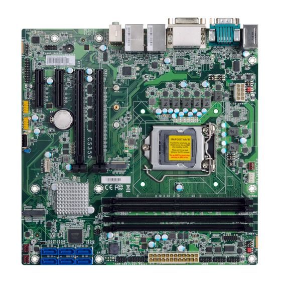
Chapter 2 HARDWARE INSTALLATION Chapter 2 - Hardware Installation X Board Layout Note: Some components are optional and only available upon re- quest. DDR4_3 DDR4_4 KB/MS SYS FAN1 USB 5/6 (USB 2.0) CPU FAN1 JP10 Important: +12V Power Electrostatic discharge (ESD) can damage your board, proces- COM2 sor, disk drives, add-in boards, and other components. -
Page 10: System Memory
Dual Channel DIMMs of the same memory configuration are on different channels. Step 1 Features • CS350-C246: Four 288-pin ECC/Non-ECC DIMM up to 64GB • CS350-Q370: Four 288-pin Non-ECC DIMM up to 64GB • Dual Channel DDR4 2400/2666 MHz Step 2... -
Page 11: Removing The Dimm Module
Chapter 2 HARDWARE INSTALLATION System Memory Installing the DIMM Module System Memory Removing the DIMM Module Please follow the steps below to install the memory card into the socket. Please follow the steps below to remove the memory card from the socket. Step 1: Press the eject tabs at both ends of the socket outward and downward to release them from DDR4 DIMM... -
Page 12: Cpu
Chapter 2 HARDWARE INSTALLATION X CPU Installing the CPU 1. Make sure the PC and all other peripheral devices connected to it have been powered down. The system board is equipped with a surface mount LGA 1151 socket. This socket is exclu- sively designed for installing a LGA 1151 packaged Intel CPU. - Page 13 Chapter 2 HARDWARE INSTALLATION Installing the CPU Installing the CPU Load lever 7-2. Two keys on the sock- 5. Lift the load lever and the load plate all the way up as shown in et and notches on the Alignment key CPU also facilitate the photo.
-
Page 14: Installing The Fan And Heat Sink
Chapter 2 HARDWARE INSTALLATION Installing the Fan and Heat Sink 4. Screw tight two of the spring screws at opposite corners into the mounting holes. And The CPU must be kept cool by using a CPU fan with heat sink. Without sufficient air circula- then proceed with the other two spring screws. -
Page 15: Jumper Settings
2280 2260 2242 SPI Flash BIOS DDR4_1 DDR4_2 Chapter 2 SMBus HARDWARE INSTALLATION PCIE1 (PCIe x16) PCIE2 (PCIe x16) SATA4/5 COM 1 Serial Mode X Jumper Settings (left/right) Intel Buzzer Clear CMOS SATA2/3 PCIE3 (PCIe x4) C246/Q370 (left/right) Battery USB 3.1 Gen 2 (USB 5/6) „... -
Page 16: Com 2 Serial Mode
Chapter 2 HARDWARE INSTALLATION Jumper Settings Jumper Settings COM 2 Serial Mode COM1 & COM2 RS232 Power Select JP6 (left) JP8 (right) JP10 JP4 (right) JP7 (right) „ COM 2 JP6, JP8, and JP10 are used to configure the COM 2 port to RS232, RS422 (Full Duplex) or RS485. -
Page 17: Digital I/O (Dio) Power Select
Line Out Line In Note Chapter 2 2280 2260 2242 SPI Flash BIOS DDR4_1 DDR4_2 HARDWARE INSTALLATION SMBus PCIE1 (PCIe x16) Jumper Settings PCIE2 (PCIe x16) SATA4/5 Digital I/O (DIO) Power Select (left/right) Intel Buzzer SATA2/3 PCIE3 (PCIe x4) C246/Q370 (left/right) Battery USB 3.1 Gen 2... -
Page 18: Rear I/O Ports
Chapter 2 HARDWARE INSTALLATION X Rear I/O Ports Rear I/O Ports PS/2 Keyboard/Mouse „ PS/2 KB/MS „ COM „ LAN 1 „ LAN 2 „ Audio „ DVI-I „ PS/2 KB/MS „ 2 x USB 2.0 „ DP++ „ 2 x USB „... -
Page 19: Usb Ports
Chapter 2 HARDWARE INSTALLATION Rear I/O Ports Rear I/O Ports USB Ports Graphics Display „ USB 6 (USB 2.0) „ USB 5 (USB 2.0) „ DP++ „ DVI-I (DVI-D Signal) „ DP++ Note DisplayPort ++ The DisplayPort (DP) is a digital display interface used to connect a display device such as a computer monitor. -
Page 20: Rj45 Lan
Chapter 2 HARDWARE INSTALLATION Rear I/O Ports Rear I/O Ports RJ45 LAN Audio „ LAN 1 „ LAN 2 „ Line-out „ Mic-in The two LAN ports allow the system board to connect to a local area network. The system board is equipped with three rear audio jacks: BIOS Setting •... -
Page 21: Com 1 (Serial) Port
Chapter 2 HARDWARE INSTALLATION Rear I/O Ports COM 1 (Serial) Port „ COM 1 „ COM 1 Pin Assignment Standard RS232 RS422 RS485 RS232 with Power DCD- +12V TXD- Data- TXD+ Data+ RXD+ N.C. DTR- DTR- RXD- N.C. DSR- DSR- N.C. -
Page 22: Internal I/O Connectors
Chapter 2 HARDWARE INSTALLATION X Internal I/O Connectors COM (Serial) Port DDR4_3 DDR4_4 „ COM Port Pin Assignment CPU FAN1 JP10 Standard RS232 with RS422 RS485 RS232 Power (COM 2) (COM 2) (COM 2) „ COM 2/3/4 from top to bottom DCD- +12V TXD-... -
Page 23: Usb Ports
Standby Chapter 2 Power HARDWARE INSTALLATION B 1/2 B 3.1 Gen 1) Internal I/O Connectors USB Ports The USB device allows data exchange between your computer and a wide range of simultane- ously accessible external Plug and Play peripherals. Front B 3/4 Panel In addition to the rear USB ports as introduced previously in this chapter, the system board... -
Page 24: Front Audio
LAN2 Front USB 3/4 Panel Chapter 2 (USB 3.1 Gen 2) HARDWARE INSTALLATION LAN LED M.2 M Key Internal I/O Connectors Internal I/O Connectors Mic In Line Out Front Audio SATA (Serial ATA) Line In Note 2280 2260 2242 SPI Flash BIOS DDR4_1 DDR4_2 SMBus... -
Page 25: Digital I/O
Chapter 2 HARDWARE INSTALLATION Internal I/O Connectors Internal I/O Connectors Digital I/O Cooling Fan Connectors System Fan 1 (left), CPU Fan (right) „ System Fan 1/2/3 „ Digital I/O „ CPU Fan (PWM) System Fan 2 (right) System Fan 3 (left) The 8-bit Digital I/O (DIO) connector allows for input/output signals of digital logical states de- fined by voltage levels. -
Page 26: Power Connector
Line Out Line In Note 2280 2260 2242 Chapter 2 SPI Flash BIOS DDR4_1 DDR4_2 HARDWARE INSTALLATION SMBus Internal I/O Connectors Internal I/O Connectors PCIE1 (PCIe x16) Power Connector Chassis Intrusion PCIE2 (PCIe x16) SATA4/5 (left/right) Intel Buzzer „ ATX 24-pin Power SATA2/3 Connector PCIE3 (PCIe x4) -
Page 27: Front Panel
Chapter 2 HARDWARE INSTALLATION Internal I/O Connectors Internal I/O Connectors Front Panel S/PDIF PWR-LED HD-LED ATX-SW RESET 11 12 „ S/PDIF Connector „ Front Panel Connector „ Front Panel Pin Assignment Assignment Assignment N.C. LED Power The Sony/Philips Digital Interface (S/PDIF) connector is for audio output to external audio equipment. -
Page 28: Battery
Chapter 2 HARDWARE INSTALLATION Internal I/O Connectors Internal I/O Connectors Battery SMBus „ SMBus „ Battery Holder The lithium ion battery addendum supplies power to the real-time clock and CMOS memory The SMBus (System Management Bus) connector is used to connect the SMBus device. It is a as an auxiliary source of power when the main power is shut off. -
Page 29: Lan Led
Chapter 2 HARDWARE INSTALLATION Internal I/O Connectors Internal I/O Connectors LAN LED Expansion Slots M.2 M Key „ LAN LED Connector M.2 E Key The LAN LED connector is used to detect the connection state of RJ45 LAN ports when the M.2 Sockets connection is made to an active network via a cable. -
Page 30: Installing The M.2 Module
Chapter 2 HARDWARE INSTALLATION Internal I/O Connectors Expansion Slots Installing the M.2 Module Before installing the M.2 module into the M.2 socket, please make sure that the following Please follow the steps below to install the card into the socket. safety cautions are well-attended. -
Page 31: Lpc
Chapter 2 HARDWARE INSTALLATION Internal I/O Connectors The LPC connector is used for debugging. „ LPC Connector „ LPC Pin Assignment Pin Assignment Pin Assignment L_CLK L_LAD1 L_RST# L_LAD0 L_FRAME# 3.3V L_LAD3 L_LAD2 SERIRQ 5VSB User's Manual | CS350...
Need help?
Do you have a question about the CS350-C246 and is the answer not in the manual?
Questions and answers