GW Instek PFR-100 Series User Manual
Multi-range dc power supply
Hide thumbs
Also See for PFR-100 Series:
- Programming manual (140 pages) ,
- User manual (149 pages) ,
- Programming manual (140 pages)
Table of Contents
Advertisement
Quick Links
Download this manual
See also:
Programming Manual
Advertisement
Chapters
Table of Contents

Related Manuals for GW Instek PFR-100 Series


Summary of Contents for GW Instek PFR-100 Series
- Page 1 99 Washington Street Melrose, MA 02176 Phone 781-665-1400 Toll Free 1-800-517-8431 Visit us at www.TestEquipmentDepot.com Multi-Range DC Power Supply PFR-100 Series USER MANUAL ISO-9001 CERTIFIED MANUFACTURER...
- Page 2 This manual contains proprietary information, which is protected by copyright. All rights are reserved. No part of this manual may be photocopied, reproduced or translated to another language without prior written consent of Good Will company. The information in this manual was correct at the time of printing. However, Good Will continues to improve products and reserves the rights to change specification, equipment, and maintenance procedures at any time without notice.
-
Page 3: Table Of Contents
TABLE OF CONTENTS Table of Contents SAFETY INSTRUCTIONS ........... 5 GETTING STARTED ............9 PFR-100 Series Overview ...... 10 Appearance .......... 13 Theory of Operation ......20 OPERATION ..............32 Set Up ..........33 Basic Operation ........44 Test Scripts .......... 58 CONFIGURATION ............ - Page 4 PFR-100 Series User Manual INDEX ................153...
-
Page 5: Safety Instructions
SAFETY INSTRUCTIONS AFETY INSTRUCTIONS This chapter contains important safety instructions that you must follow during operation and storage. Read the following before any operation to insure your safety and to keep the instrument in the best possible condition. Safety Symbols These safety symbols may appear in this manual or on the instrument. - Page 6 PFR-100 Series User Manual Do not dispose electronic equipment as unsorted municipal waste. Please use a separate collection facility or contact the supplier from which this instrument was purchased. Safety Guidelines Do not place any heavy object on the PFR-100.
- Page 7 SAFETY INSTRUCTIONS (Pollution Degree) EN61010-1:2010 specifies the pollution degrees and their requirements as follows. The PFR-100 falls under degree 2. Pollution refers to “addition of foreign matter, solid, liquid, or gaseous (ionized gases), that may produce a reduction of dielectric strength or surface resistivity”.
- Page 8 PFR-100 Series User Manual Power cord for the United Kingdom When using the power supply in the United Kingdom, make sure the power cord meets the following safety instructions. NOTE: This lead/appliance must only be wired by competent persons WARNING: THIS APPLIANCE MUST BE EARTHED...
-
Page 9: Getting Started
After going through the overview, please read the theory of operation to become familiar with the operating modes, protection modes and other safety considerations. PFR-100 Series Overview ......... 10 Series lineup ................... 10 Main Features................. 10 Accessories ..................11 Appearance .............. -
Page 10: Pfr-100 Series Overview
PFR-100 Series User Manual PFR-100 Series Overview Series lineup The PFR-100 series consists of 2 models, covering a number of different current, voltage and power capacities: Model name Operation Voltage Operation Current Rated Power PFR-100L 0-50V 0-10A 100W PFR-100M 0-250V... -
Page 11: Accessories
GETTING STARTED Web server monitoring and control. (The function is activated when connecting to LAN Interface) Analog monitor output. Remote sensing to compensate for voltage drop in load leads. Built-in front panel and rear panel output terminal. - Page 12 PFR-100 Series User Manual Optional Part number Description Accessories GRA-431-J-100 Rack mount adapter (JIS) with AC 100V GRA-431-J-200 Rack mount adapter (JIS) with AC 200V GRA-431-E-100 Rack mount adapter (EIA) with AC 100V GRA-431-E-200 Rack mount adapter (EIA) with AC 200V...
-
Page 13: Appearance
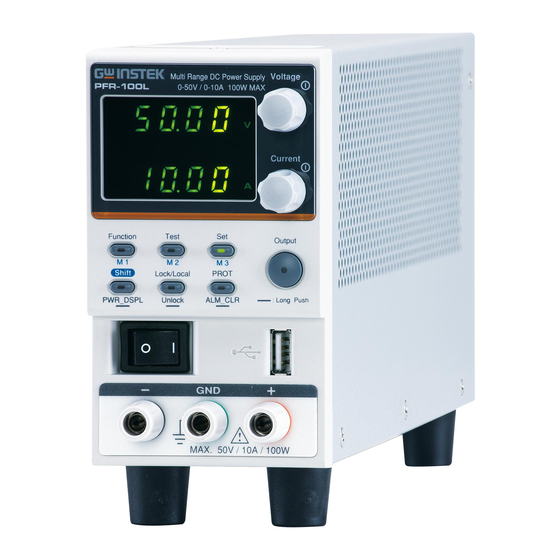
GETTING STARTED Appearance Front Panel Voltage Multi-Range DC Power Supply 0-50V / 0-10A 100W MAX PFR-100L Display Area Current Function Test Output Lock/Local PROT Shift PWR_DSPL Unlock ALM_CLR : Long Push MAX. 50V / 10A / 100W Display Area The display area shows setting values, output values and parameter settings. - Page 14 PFR-100 Series User Manual (+Shift) Used to recall the M1 setup. M1 Button (+Shift and hold) Used to save the current setup to M1. Used to run customized scripts for 4. Test Button TEST testing. (+Shift) Used to recall the M2 setup.
- Page 15 GETTING STARTED Used to set and display OVP, OCP 8. PROT Button PROT and UVL. ALM_CLR (Long push) Used to release ALM_CLR protection functions that have been Button activated. Used to turn the output on or off. 9. Output Output Button Used to turn the power on/off.
-
Page 16: Display Area
PFR-100 Series User Manual Display Area 23 24 Lights up when CV Slew Rate Priority is 13. VSR LED enabled. Lights in green during constant voltage mode. 14. CV LED Lights in green during remote control. 15. RMT LED Lights in red when a protection function has 16. - Page 17 GETTING STARTED Lights in green when the memory value are 23. M2 LED being recalled or saved. Lights in green when the memory value are 24. M3 LED being recalled or saved. Display Voltage or Watt unit. 25. V or W LED Lights up when a Test Script has been 26.
-
Page 18: Rear Panel
PFR-100 Series User Manual Rear Panel Analog control protection cover N.C. N.C. RS232 / RS485 GPIB 100 240V 47 63Hz 150VA MAX. USB port for controlling the PFR-100 remotely. 1. USB Ethernet port for controlling the PFR-100 2. LAN remotely (Factory Installed Options). - Page 19 GETTING STARTED External analog remote control connector. 6. J1 7. Ground Connectors for grounding the output. Screw It uses a 10 pin connector and a plug for the 8. Output output and sense terminal connections. Terminals AC inlet. Line Voltage Input...
-
Page 20: Theory Of Operation
PFR-100 Series User Manual Theory of Operation The theory of operation chapter describes the basic principles of operation, protection modes and important considerations that must be taken into account before use. Operating Area Description The PFR-100 power supplies are regulated DC... - Page 21 GETTING STARTED constant voltage power supply. If however, the power supply is configured such that the total output (current x voltage output) exceeds the rated power output, the effective output is actually limited to the power limit of the unit. In this case the output current and voltage then depend purely on the load value.
-
Page 22: Cc And Cv Mode
PFR-100 Series User Manual CC and CV Mode When the power supply is operating in CC and CV mode Description constant current mode (CC) a constant current will be supplied to the load. When in constant current mode the voltage output can vary, whilst the current remains constant. -
Page 23: Slew Rate
GETTING STARTED Conversely the power supply will operate in CC mode when the load resistance is less than the critical resistance. In CC mode the current output is equal to I and the voltage output is less than V Crossover >R point <R... -
Page 24: Bleeder Control
PFR-100 Series User Manual High Speed Priority Slew rate = mode Enabled Bleeder Control The PFR-100 DC power supplies employ a Background bleed resistor in parallel with the output terminals. PFR-100 Bleed Load resistor Bleed resistors are designed to dissipate the... -
Page 25: Sink Current Table
GETTING STARTED By default the bleed resistance is on. For battery Note charging applications, be sure to turn the bleed resistance off as the bleed resistor can discharge the connected battery when the unit is off. Sink Current Table Sink current (reference value) from an external Background voltage source according to the bleeder circuit setting. -
Page 26: Alarms
PFR-100 Series User Manual Alarms The PFR-100 power supplies have a number of protection features. When one of the protection alarms is set, the ALM icon on the display will be lit. For details on how to set the protection modes, please see page 44. -
Page 27: Considerations
Vo_sense > Vo_real + 1V Force Shutdown is not activated as a result of Shutdown the PFR-100 series detecting an error. It is a function that is used to turn the output off through the application of a signal from the rear-panel analog control connector when an abnormal condition occurs. - Page 28 PFR-100 Series User Manual the actual current can exceed the indicated value. For pulsed loads, the current limit must be increased, or a power supply with a greater capacity must be chosen. As shown below, a pulsed load may exceed the current limit and the indicated current on the power supply ammeter.
- Page 29 GETTING STARTED (Ω) ≤ E (V) ÷ I PFR-100 Load The current output will decrease by the amount of Note current absorbed by the resistor. Ensure the resistor used can withstand the power capacity of the power supply/load. When the power supply is connected to a load Reverse Current: such as a battery, reverse current may flow Accumulative...
-
Page 30: Grounding
PFR-100 Series User Manual Grounding The output terminals of the PFR-100 power supplies are isolated with respect to the protective grounding terminal. The insulation capacity of the load, the load cables and other connected devices must be taken into consideration when connected to the protective ground or when floating. - Page 31 GETTING STARTED If the positive or negative terminal is connected Grounded output terminal to the protective ground terminal, the insulation capacity needed for the load and load cables is greatly reduced. The insulation capacity only needs to be greater than the maximum output voltage of the power supply with respect to ground.
- Page 32 PFR-100 Series User Manual PERATION Set Up ..............33 Power Up ..................33 Wire Gauge Considerations ............34 Output Terminals ................35 Connection with the rear panel output terminal ...35 Connection with the front panel output terminal ..37 Using the Output Terminal Cover ..........38 Using the Rack Mount Kit ............
-
Page 33: Operation
OPERATION Set Up Power Up Make sure that the power source is shut off. Background Use the AC power cable supplied with the product. 1. Connect the power cord to Steps the rear panel socket. 2. Press the POWER switch on. If used for the first time, the default settings will appear on the display, otherwise The PFR-100 recovers the state right before the power was last turned... -
Page 34: Wire Gauge Considerations
PFR-100 Series User Manual Wire Gauge Considerations Before connecting the output terminals to a Background load, the wire gauge of the cables should be considered. It is essential that the current capacity of the load cables is adequate. The rating of the cables must equal or exceed the maximum current rated output of the instrument. -
Page 35: Output Terminals
OPERATION Output Terminals Connection with the rear panel output terminal The PFR-100 series use a 10 pin socket for the Background output voltage and sense connections. The corresponding plugs (DECA SwitchLab MC420-38110Z) should be used to connect the terminals to the appropriate cable. - Page 36 PFR-100 Series User Manual -V: -V terminals (x3) Output Connector Pinout -S: -Sense terminal NC: Not connected (x2) +S: +Sense terminal -V -S +V: +V terminals (x3) +S +V Unscrew the appropriate Wiring the Loosen terminal anticlockwise to Connector Plug Tighten release the receptacle.
-
Page 37: Connection With The Front Panel Output Terminal
OPERATION 5. Connect the positive load cable to the positive output terminal and the negative cable to the negative output terminal. 6. If using voltage sense, remove the sense terminal joining cables and connect sensing wires to the load(s). 7. Reattach the output terminal cover. Connection with the front panel output terminal Be sure to examine if the output CAUTION... -
Page 38: Using The Output Terminal Cover
PFR-100 Series User Manual 3. Fix the load cables firmly to eliminate loose connections from the front output terminals and load cables. For safety, Never output power through both the WARNING front and rear output terminals. Using the Output Terminal Cover 1. -
Page 39: Using The Rack Mount Kit
OPERATION Using the Rack Mount Kit The PFR-100 series has an optional Rack Mount Background Kit (GW Instek part number: [JIS] GRA-431-J, [EIA] GRA-431-E[EIA]) that can be used to hold 5 units into rack. Rack mount diagram How to Use the Instrument... -
Page 40: Reset To Factory Default Settings
PFR-100 Series User Manual 2. Turn the Voltage knob till 0.05 Voltage volts is shown on the voltage display. → 3. Repeatedly press the Voltage knob until the first digit is highlighted. This will allow the voltage to be edited in 1 volt steps. - Page 41 OPERATION 2. The display should show F-01 on the top and the configuration setting for F-01 on the bottom. 3. Rotate the Voltage knob to change Voltage the F setting to F-88 (Factory Set Value). 4. Use the Current knob to set the Current F-88 setting to 1 (Return to factory default settings).
-
Page 42: View System Version And Build Date
PFR-100 Series User Manual View System Version and Build Date The F-89 configuration setting allows you to Background view the PFR-100 version number, build date, keyboard version, analog-control version. 1. Press the Function key. The Steps Function Function key will light up. - Page 43 OPERATION 5. Press the Function key again to Function exit. The Function key light will turn off. Main Program Version: V01.00, 2017/06-01 Example 0-01: Version 1-00: Version 2-20: Build On-Year. 3-17: Build On-Year. 4-06: Build On-Month. 5-01: Build On-Day. Keyboard CPLD Version: 0x3305 Example 6-33: Keyboard CPLD Version.
-
Page 44: Basic Operation
PFR-100 Series User Manual Basic Operation This section describes the basic operations required to operate the power supply. Setting OVP/OCP → from page 44 C.V. priority mode → from page 47 C.C. priority mode → from page 50 Display mode → page 53 Panel lock →... - Page 45 OPERATION voltage that is less than the UVL setting. The UVL setting range is from 0% ~ 105% of the rated output voltage. Example: OVP alarm Before setting the protection settings: • Ensure the load is not connected. • Ensure the output is turned off. You can use the Function settings (F-13 and F-14) Note to apply limits to the voltage and current settings,...
- Page 46 PFR-100 Series User Manual 1. Press the PROT key. The PROT key Steps PROT lights up. 2. The OVP protection function will be displayed on the voltage display and the setting will be displayed on the current display. Protection function...
-
Page 47: Set To C.v. Priority Mode
OPERATION Set to C.V. Priority Mode When setting the power supply to constant voltage mode, a current limit must also be set to determine the crossover point. When the current exceeds the crossover point, the mode switches to C.C. mode. For details about C.V. operation, see page 22. C.C. and C.V. mode have two selectable slew rates: High Speed Priority and Slew Rate Priority. - Page 48 PFR-100 Series User Manual 4. Use the Current knob to set the F- Current 03 setting. Set F-03 to 0 (CV High Speed Priority) or 2 (CV Slew Rate Priority). 0 = CV High Speed Priority F-03 2 = CV Slew Rate Priority 5.
- Page 49 OPERATION 9. Use the Voltage knob to set the Voltage voltage. Notice the Set key becomes illuminated when Note setting the current or voltage. If the Voltage or Current knobs are unresponsive, press the Set key first. 10. Press the Output key. The Output Output key becomes illuminated.
-
Page 50: Set To C.c. Priority Mode
PFR-100 Series User Manual Set to C.C. Priority Mode When setting the power supply to constant current mode, a voltage limit must also be set to determine the crossover point. When the voltage exceeds the crossover point, the mode switches to C.V. - Page 51 OPERATION 4. Use the Current knob to set the F- Current 03 setting. Set F-03 to 1 (CC High Speed Priority) or 3 (CC Slew Rate Priority) and save. 1 = CC High Speed Priority F-03 3 = CC Slew Rate Priority 5.
- Page 52 PFR-100 Series User Manual 9. Use the Current knob to set the Current current. Notice the Set key becomes illuminated when Note setting the current or voltage. If the Voltage or Current knobs are unresponsive, press the Set key first.
-
Page 53: Display Modes
OPERATION Display Modes The PFR-100 series power supplies allow you to view the output in three different modes: voltage and current, voltage and power or current and power. 1. Hold the PWR_DSPL key for 3 Steps seconds. The display changes to PWR_DSPL voltage and power (V/W). -
Page 54: Panel Lock
PFR-100 Series User Manual Panel Lock The panel lock feature prevents settings from being changed accidentally. When activated, the Lock/Local key will become illuminated and all keys and knobs except the Lock/Local key and Output key (if active) will be disabled. -
Page 55: Recall Setup
OPERATION 3. When the setup is saved the unit will beep, the setup will be saved and the memory number will be shown on the display. Saved setup Recall Setup The PFR-100 has 3 dedicated keys (M1, M2, M3) to recall setups. 1. -
Page 56: Remote Sensing
PFR-100 Series User Manual Remote Sensing Remote sense is used to compensate for the voltage drop seen across load cables due to the resistance inherent in the load cables. The remote sense terminals are connected to the load terminals to determine the voltage drop across the load cables. - Page 57 OPERATION 1. Connect the +S terminal to the positive Single Load potential of the load. Connect the -S terminal to the negative potential of the load. PFR-100 Load Output Input Output Input 2. Operate the instrument as normal. See the Basic Operation chapter for details.
-
Page 58: Test Scripts
Each test script is programmed in a scripting language. For more information on how to create test scripts, please contact GW Instek. Test script file format→ from page 59 Test script settings → from page 59 Setting the test script settings →... -
Page 59: Test Script File Format
OPERATION Test Script File Format The test files are saved in *.tst file format. Background Each file is saved as tXXX.tst, where XXX is the save file number 001~010. Test Script Settings Runs test script from the internal memory. A Test Run script must first be loaded into the internal memory before it can be run. -
Page 60: Setting The Test Script Settings
PFR-100 Series User Manual Displays the available T-05 memory in bytes. Setting the Test Script Settings The test script settings (T-01~T-04) are set with Steps the Test key. 1. Press the Test key. The Test key TEST will light up. -
Page 61: Load Test Script
OPERATION 5. Press the Voltage knob to complete Voltage the setting. Press the Test key again to exit the Exit TEST Test settings. The Test key light will turn off. Load Test Script Before a test script can be run, it must first be Overview loaded into the internal memory. -
Page 62: Run Test Script
PFR-100 Series User Manual 3. Configure T-02 (Test Load) to load Page 60 test script to internal memory. T-02 range 1~10 (t001 ~t010) Test Setting Memory number Test Setting Configure 4. The script will now be available in the internal memory. - Page 63 OPERATION 2. Configure T-01 (Run Test) Page 60 3. If there are no errors during loading, the script engine will enter the wait state. The wait state indicates that the unit is ready to execute the script. Wait state To execute the script, press the ...
-
Page 64: Export Test Script
PFR-100 Series User Manual Export Test Script The Export Test function saves the test file to the Overview root directory of a USB flash drive. Files will be saved as tXXX.tst where XXX is the file number 001~010 from which the test script was exported to. -
Page 65: Remove Test Script
OPERATION Error messages: If you load a file that is not Note present on the USB drive “Err 003” will be displayed on the display. If you try to export a test script from an empty memory location “Err 003” will be displayed on the display. -
Page 66: Configuration
PFR-100 Series User Manual ONFIGURATION Configuration Overview ......... 67 Configuration Table ..............67 Normal Function Settings ............70 Interface Configuration Settings ..........74 USB / GPIB Settings ............74 LAN Settings ..............75 UART Settings ..............76 System Settings ................77 Power On Configuration Settings ..........78 Special Function ................ -
Page 67: Configuration Overview
CONFIGURATION Configuration Overview Configuration of the PFR-100 power supplies is divided into five different configuration settings: Normal Function, Interface Configuration Settings, System Configuration Settings, Power ON Configuration and Special Function Settings. Power ON Configuration differs from the other settings in that the settings used with Power ON Configuration settings can only be set during power up. - Page 68 PFR-100 Series User Manual Buzzer ON/OFF control F-10 0 = OFF, 1 = ON Detection Time of OCP F-12 0.0 ~ 2.0 sec 0 = OFF (The limit function of Current Setting Limit current setting is disabled.) F-13 (I-Limit) 1 = ON (The limit function of current setting is enabled.)
- Page 69 CONFIGURATION Subnet Mask-3 F-45 0~255 Subnet Mask-4 F-46 0~255 Gateway-1 F-47 0~255 Gateway-2 F-48 0~255 Gateway-3 F-49 0~255 Gateway-4 F-50 0~255 DNS address-1 F-51 0~255 DNS address-2 F-52 0~255 DNS address-3 F-53 0~255 DNS address-4 F-54 0~255 Web Password F-60 0 = Disable, 1 = Enable Enable/Disable Web Enter Password...
-
Page 70: Normal Function Settings
PFR-100 Series User Manual Power On Configuration Settings* 0 = Panel control (local) 1 = External Voltage control 2 = External Resistance control- F-90 Rising CV Control 3 = External Resistance control- Falling 0 = Panel control (local) 1 = External Voltage control... - Page 71 CONFIGURATION Normal Function Settings Delays turning the output on for a designated Output ON Delay Time amount of time. The Delay indicator will light when the Delay time is not 0. Note: The Output ON Delay Time setting has a maximum deviation (error) of 20ms.
- Page 72 PFR-100 Series User Manual Selects High Speed Priority or Slew Rate V-I Mode Priority for CV or CC mode. The voltage or current slew rate can only be edited if CC/CV Slew Rate Priority is selected. The ISR indicator will be lit for CC Slew Rate Priority and the VSR indicator will be lit for CV Slew Rate Priority.
- Page 73 CONFIGURATION Only applicable if V-I Mode is set to CC Slew Falling Current Slew Rate Rate Priority. (F-03 must be 3) F-07 0.01A/s ~ 20.00A/s (PFR-100L) 0.001A/s ~ 4.000A/s (PFR-100M) Bleeder control turns ON/OFF the bleeder Bleeder ON/OFF resistor. When set to AUTO the bleeder resistor is automatically turned on when the output is turned on and turned off when the output or power is turned off.
-
Page 74: Interface Configuration Settings
PFR-100 Series User Manual If the parameter sets to "1 = ON", limit the Voltage Setting Limit setting of output voltage not exceed the OVP setting value (approximately 95 % of the OVP trip point). If the parameter sets to "0 = OFF", when output voltage exceed the OVP value, the OVP function will be activated. -
Page 75: Lan Settings
CONFIGURATION Displays the rear panel USB-B port state. This Rear Panel USB setting is not configurable. Status F-21 0 = None, 1 = Linking to PC Sets the GPIB address. GPIB Address F-23 0 ~ 30 Shows the status of the GPIB option port. Show GPIB available Status 0 = No GPIB, 1 = GPIB is... -
Page 76: Uart Settings
PFR-100 Series User Manual F-47~F-50 0~255 Sets the DNS address. The DNS address is split DNS Address 1~4 into 4 parts. F-51~ F-54 0~255 Turns a web password on/off. Web Password Enable/Disable F-60 0 = Disable, 1 = Enable Sets the web password. -
Page 77: System Settings
CONFIGURATION Set the master/slave/display-information UART Multi-Drop control parameters of a unit when using Multi-Drop remote control. F-77 0 = Disable, 1 = Master, 2 = Slave, 3 = Display Information Displays the Multi-Drop status on the master UART Multi-Drop unit for each slave unit belonging to the Multi- status Drop bus. -
Page 78: Power On Configuration Settings
PFR-100 Series User Manual Power On Configuration Settings Sets the constant voltage (CV) control mode CV Control between local and external voltage/resistance control. F-90 0 = Panel control (local) 1 = External Voltage control 2 = External Resistance control-Rising 3 = External Resistance control-Falling... -
Page 79: Special Function
CONFIGURATION Special Function The special function setting is used to access Special Function calibration, firmware updates and other special functions. The special function setting has a password that is used to access the special function menu. The password used determines which function is accessed. - Page 80 PFR-100 Series User Manual 3. Rotate the Voltage knob to change Voltage the F setting. F-00~F-61, F-70~F-78, Range F-88~F-94 4. Use the Current knob to set the Current parameter for the chosen F setting. Press the Voltage knob to save the Voltage configuration setting.
-
Page 81: Setting Power On Configuration Settings
CONFIGURATION Setting Power On Configuration Settings The Power On configuration settings can only Background be changed during power up to prevent the configuration settings being inadvertently changed. Ensure the load is not connected. Ensure the power supply is off. ... - Page 82 PFR-100 Series User Manual 5. Press the Voltage knob to save the Voltage configuration setting. ConF will be displayed when successful. Cycle the power to save and exit the Exit configuration settings.
-
Page 83: Analog Control
ANALOG CONTROL NALOG CONTROL The Analog Control chapter describes how to control the voltage or current output using an external voltage or resistance, monitor the voltage or current output as well as remotely turning off the output or shutting down the power supply. -
Page 84: Analog Remote Control Overview
PFR-100 Series User Manual Analog Remote Control Overview The PFR-100 power supply series have a number of analog control options. The Analog Control connectors are used to control output voltage and current using external voltage or resistance. The power supply output can also be controlled using external switches. -
Page 85: Analog Control Connector Overview
ANALOG CONTROL Analog Control Connector Overview The Analog Control Connector(J1) is a 20pin Overview connector that can be used with the plug for wiring connection. The connector is used for all analog remote control. The pins used determine what remote control mode is used. Pin Assignment Pin name Pin number... - Page 86 PFR-100 Series User Manual Alarm Clear 11 Alarm clear line. Alarms are cleared when a low TTL signal is applied. Shutdown 12 Output shutdown control line. The output is turned off when a low TTL signal is applied. A COM 13 This is the common line for external signal pins 11, 12, 14, 16, 18, 19, and 20.
- Page 87 ANALOG CONTROL EXT-V/R CC 18 This line uses an external voltage or resistance to CONT control the output current. External voltage control (F-91: 1); External resistor control (F-91: 2, F-91:3) 0 to 10 V or 0 to 10k ; 0 % to 100 % of the rated output current.
-
Page 88: External Voltage Control Of Voltage Output
PFR-100 Series User Manual External Voltage Control of Voltage Output External voltage control of the voltage output is Background accomplished using the analog control connector on the rear panel. A voltage of 0~10V is used to control the full scale voltage of the instrument, where: Output voltage = full scale voltage ×... - Page 89 ANALOG CONTROL If the wire shield needs to be grounded at the Connection- alt. voltage source (EXT-V), then the shield cannot shielding also be grounded at the negative (-) terminal output of the PFR-100 power supply. This would short the output. EXT-V PFR-100 +...
-
Page 90: External Voltage Control Of Current Output
PFR-100 Series User Manual The input impedance for external voltage control is Note a high impedance OPA input. A COM Use a stable voltage supply for the external voltage control. CV and CC Slew Rate Priority are disabled for V-I Note mode (F-03) when using external voltage control. - Page 91 ANALOG CONTROL When connecting the external voltage source to Connection the analog connector, use shielded or twisted paired wiring. EXT-V PFR-100 + Analog connector - 2 core shielded wire or twisted Output pair Terminal Pin18 → EXT-V (+) Pin17 → EXT-V (-) Wire shield →...
- Page 92 PFR-100 Series User Manual 11. Set the F-91 power on Page 81 configuration setting to 1 (CC control – Ext voltage). Be sure to cycle the power after the power on configuration has been set. 12. Press the Function key and confirm...
-
Page 93: External Resistance Control Of Voltage Output
ANALOG CONTROL External Resistance Control of Voltage Output External resistance control of the voltage output Background is accomplished using the analog connector on the rear panel. A resistance of 0Ω~10kΩ is used to control the full scale voltage of the instrument. - Page 94 PFR-100 Series User Manual EXT-R PFR-100 Connection Analog connector 2 core shielded wire or twisted Output pair Terminal Pin16 → EXT-R Pin15 → EXT-R Wire shield → negative (-) output terminal 1. Connect the external resistance according to the Steps connection diagrams above.
-
Page 95: External Resistance Control Of Current Output
ANALOG CONTROL CV and CC Slew Rate Priority are disabled for V-I Note mode (F-03) when using external resistance control. See the normal function settings on page External Resistance Control of Current Output External resistance control of the current output Background is accomplished using the analog connector on the rear panel. - Page 96 PFR-100 Series User Manual EXT-R PFR-100 Connection Analog connector 2 core shielded wire or twisted Output pair Terminal Pin18 → EXT-R Pin17 → EXT-R Wire shield → negative (-) output terminal 1. Connect the external resistance according to the Steps connection diagrams above.
-
Page 97: External Control Of Output
ANALOG CONTROL External Control of Output The output can be turned on or off externally Background using a switch. The analog control connector can be set to turn the output on from a high or low signal. The voltage across pins 14 and 13 are internally pulled to +5V ±5% @ 500uA with 10kΩ... - Page 98 PFR-100 Series User Manual 2. Press the Function key and confirm Function the new configuration setting.(F- 94= 0 or 1) 3. The switch is now ready to set the output on or off. When using a switch over long distances, please...
-
Page 99: External Control Of Shutdown
ANALOG CONTROL Output off (High=on) Output off (Low=on) Output ON/OFF Delay Time (F-01, F-02) are Note disabled when the output is set to external control. See the normal function settings on 70 for details. External control of Shutdown The output of the power supplies can be Background configured to shut down via an external switch. -
Page 100: External Control Of Alarm Clear
PFR-100 Series User Manual 1. Connect the external switches according to the Steps connection diagrams above. 2. The switch will now shut down the power supply when shorted. When using a switch over long distances, please Note use a switch relay to extend the line from the coil side of the relay. - Page 101 ANALOG CONTROL Switch PFR-100 Connection Analog connector 2 core shielded wire or twisted Output pair Terminal Pin11→ Switch Pin13 → Switch Wire shield → negative (-) output terminal 1. Connect the external switches according to the Steps connection diagrams above. 2.
-
Page 102: Remote Monitoring
PFR-100 Series User Manual Remote Monitoring The PFR-100 power supplies have remote monitoring support for current and voltage output. They also support monitoring of operation and alarm status. External monitoring of output voltage and current → from page External monitoring of operation mode and alarm status → from... - Page 103 ANALOG CONTROL PFR-100 IMON Connection Analog connector I MON → Output Terminal Pin17 → Neg (-) Pin19 → Pos (+) Maximum current is 5mA. Ensure the sensing Note circuit has an input impedance greater than 1MΩ. The monitor outputs are strictly DC and should not be used to monitor analog components such as transient voltage response or ripple etc.
-
Page 104: External Operation And Status Monitoring
PFR-100 Series User Manual External Operation and Status Monitoring The analog connector can also be used to Background monitor the status operation and alarm status of the instrument. The pins are isolated from the power supply internal circuitry by photo couplers. Status... - Page 105 ANALOG CONTROL OUT ON 6 On when the output is on Status (open-collector photocoupler output). Schematic Pins 2, 3, 4, 5, 6 1 (Status COM1) Below are 4 example timing diagrams covering Timing diagrams a number of scenarios. Note that pins 2~6 are all active low.
- Page 106 PFR-100 Series User Manual The diagram below shows the timing diagram CC MODE: Output turned on when the output is turned on when the PFR-100 is set to CC mode. CV status CC status Output status The diagram below shows the output status CC MODE: lines when the output is turned off in CC mode.
-
Page 107: Communication Interface
OMMUNICATION INTERFACE This chapter describes basic configuration of IEEE488.2 based remote control. For a command list, refer to the programming manual, downloadable from GW Instek website, www.gwinstek.com Interface Configuration .......... 108 USB Remote Interface ..............108 Configuration ..............108 USB CDC Function Check ........... 109 GPIB Remote Interface ............. -
Page 108: Interface Configuration
PFR-100 Series User Manual Interface Configuration USB Remote Interface When using the USB Remote Interface, The USB Note port on the front panel will become disabled and fail to be used. Configuration Type A, host PC side connector Configuration Rear panel Type B, slave... -
Page 109: Usb Cdc Function Check
COMMUNICATION INTERFACE 4. The RMT indicator will turn on when a remote connection has been established. RMT indicator USB CDC Function Check Invoke a terminal application such as Realterm. Functionality check To check the COM port No., see the Device Manager in the PC Run this query command via the terminal application after the instrument has been... -
Page 110: Gpib Remote Interface
GPIB Remote Interface Configuration To use GPIB, the optional GPIB option (GW Instek part number: PFR-GL) must be installed. This is a factory installed option and cannot be installed by the end-user. Only one GPIB address can be used at a time. -
Page 111: Gpib Function Check
COMMUNICATION INTERFACE 7. The RMT indicator will turn on when a remote connection has been established. RMT indicator Maximum 15 devices altogether, 20m cable GPIB constraints length, 2m between each device Unique address assigned to each device At least 2/3 of the devices turned On ... - Page 112 PFR-100 Series User Manual 2. From the Configuration panel access; My System>Devices and Interfaces>GPIB 3. Press Scan for Instruments. 4. Select the device (GPIB address of PFR-100) that now appears in the System>Devices and Interfaces > GPIB-USB-HS “GPIBX” node. 5. Click on the VISA Properties tab on the bottom.
- Page 113 COMMUNICATION INTERFACE 7. Click on Configuration. 8. Click on the GPIB Settings tab and confirm that the GPIB settings are correct. 9. Click on the I/O Settings tab. 10. Make sure the Enable Termination Character check box is checked, and the terminal character is \n (Value: xA).
- Page 114 PFR-100 Series User Manual 12. Click on Input/Output. 13. Click on the Basic I/O tab. 14. Enter *IDN? in the Select or Enter Command drop down box. 15. Click Query. 16. The *IDN? query will return the Manufacturer, model name, serial number and firmware version in the dialog box.
-
Page 115: Uart Remote Interface
COMMUNICATION INTERFACE For further details, please see the programming Note manual, available on the GW Instek web site @ www.gwinstek.com. UART Remote Interface Configure UART The PFR-100 uses the IN & OUT ports for Overview UART communication coupled with RS232 (GW Instek Part number: PSU-232) or RS485 adapters (GW Instek part number: PSU-485). - Page 116 PFR-100 Series User Manual RS485 cable with DB-9 Connector Remote IN Port Remarks DB9 & RJ-45 Pin No. Name Pin No. Name shielded Housing Shield Housing Shield connectors from PSU-485 TXD - RXD - Twisted connection kit pair TXD +...
- Page 117 COMMUNICATION INTERFACE Parity: 0 = none, 1 = odd, 2 = F-73 = 0 ~2 even F-74 = 0 or 1 Stop bits: 0 = 1, 1 = 2 F-75 = 0 TCP: 0 = SCPI UART address for multi-unit F-76 = 0~30 remote connection.
-
Page 118: Uart Function Check
PFR-100 Series User Manual UART Function Check To test the USB CDC functionality, National Background Instruments Measurement and Automation Explorer can be used. This program is available on the NI website, www.ni.com., via a search for the VISA Run-time Engine page, or “downloads”... - Page 119 COMMUNICATION INTERFACE 4. The Device Manager will show up CDC- WXXXXXX on “Other Devices”. 5. Select the CDC-WXXXXXX and click the right button of mouse to "Update Driver Software".
- Page 120 PFR-100 Series User Manual 6. Select "Locate and install driver software manually." 7. Indicate the driver folder to the system and then press "Next". And this folder should consist of below 2 files. The USB driver of PFR-100 can be downloaded...
- Page 121 COMMUNICATION INTERFACE 8. Windows 7 will install the driver for a while. 9. If everything works fine, you may get below message. And the COM53 is the USB CDC ACM port of PFR-100.
- Page 122 PFR-100 Series User Manual 10. Double check the "Device Manager". The port should like below. Steps 1~10 are for the USB CDC Driver installation. 11. Start the NI Measurement and Automation Explorer (MAX) program. Using Windows, press: Start>All Programs>National Instruments>Measurement & Automation...
- Page 123 COMMUNICATION INTERFACE 12. From the Configuration panel access; My System>Devices and Interfaces>Network Devices 13. Click Open VISA Test Panel. 14. Click the Configuration icon, 15. Click on I/O Settings. 16. Make sure the Enable Termination Character check box is checked, and the terminal character is \n (Value: xA).
- Page 124 PFR-100 Series User Manual 20. Click the Query button. 21. The *IDN? query will return the Manufacturer, model name, serial number and firmware version in the dialog box. GW-INSTEK,PFR-100L,TW1234567,01.01.12345678...
-
Page 125: Multiple Unit Connection
COMMUNICATION INTERFACE Multiple Unit Connection The PFR-100 power supplies can have up to 31 units daisy-chained together using the 8 pin connectors (IN OUT ports) on the rear panel. The first unit (master) in the chain is remotely connected to a PC using USB, GPIB or LAN (Multi-Drop mode). - Page 126 PFR-100 Series User Manual 4. Connect all the End terminal Unit #N connector remaining units between RS 485/232 the OUT port and the IN port with the slave serial Slave serial link link cable (black plug) cable (black plug) Unit #2...
- Page 127 COMMUNICATION INTERFACE 11. You can check the slaves’ addresses by using the F-77 parameter on the master unit. Display on each slave units the configured address. This can show if identical F-77 = 3 addresses have been assigned individually to each slave units.
-
Page 128: Multiple Units Function Check
PFR-100 Series User Manual PSU-232 or PSU- TXD - RXD - 485 connection TXD + RXD + RXD - TXD - RXD + TXD + Multiple units Function Check Invoke a terminal application such as Realterm. Functionality check To check the COM port No, see the Device Manager in the PC. - Page 129 COMMUNICATION INTERFACE INST:SEL 5 *IDN? GW-INSTEK,PFR-100M,TW1234567, 01.01.12345678 Selects the unit with address 5 and returns its identity string. INST:SEL 6 Selects the unit with address 6 (not configured in our example). An error is displayed on the master front panel. SYST:ERR? Settings conflict Query the system errors.
-
Page 130: Configure Ethernet Connection
The PFR-100 series supports both DHCP connections so the instrument can be automatically connected to an existing network or alternatively, network settings can be manually configured. -
Page 131: Web Server Remote Control Function Check
COMMUNICATION INTERFACE 2. Press the Function key to enter the Page 79 Normal configuration settings. Set the following LAN settings: Interface port select & Turn F-29 = 6 LAN(Web) on F-37 = 1 Enable DHCP F-60 = 0 or 1 Set to 0 to disable web password, set to 1 to enable web password. - Page 132 PFR-100 Series User Manual F-41 = CCC IP Address part 3 of 4 F-42 = DDD IP Address part 4 of 4 http:// AAA.BBB.CCC.DDD The web browser interface appears. The web browser interface allows you to access the following: Network configuration settings ...
-
Page 133: Sockets Server Configuration
COMMUNICATION INTERFACE Sockets Server Configuration This configuration example will configure the Configuration PFR-100 socket server. The following configuration settings will manually assign the PFR-100 an IP address and enable the socket server. The socket server port number is fixed at 2268. 1. -
Page 134: Socket Server Function Check
PFR-100 Series User Manual Socket Server Function Check To test the socket server functionality, National Background Instruments Measurement and Automation Explorer can be used. This program is available on the NI website, www.ni.com., via a search for the VISA Run-time Engine page, or “downloads”... - Page 135 COMMUNICATION INTERFACE 4. Select Manual Entry of Raw Socket from the popup window. 5. Enter the IP address and the port number of the PFR-100. The port number is fixed at 2268. 6. Click the Validate button. 7. A popup will appear if a connection is successfully established.
- Page 136 PFR-100 Series User Manual 9. Next configure the Alias (name) of the PFR-100 connection. In this example the Alias is: PFR_DC1 10. Click finish. 11. The IP address of the PFR-100 will now appear under Network Devices in the configuration panel.
- Page 137 COMMUNICATION INTERFACE 13. Click the Configuration icon, 14. Click on I/O Settings. 15. Make sure the Enable Termination Character check box is checked, and the terminal character is \n (Value: xA). 16. Click Apply Changes. 17. Click the Input/Output icon. 18.
- Page 138 PFR-100 Series User Manual GW-INSTEK,PFR-100L,TW1234567,01.01.12345678...
-
Page 139: Faq
• How often should the power supply be calibrated? • The OVP voltage is triggered earlier than expected. • Can I combine more than 1 cable together for the output wiring? • The accuracy does not match the specification. How often should the power supply be calibrated? The PFR-100 should be calibrated by an authorized service center at least every 2 years. - Page 140 PFR-100 Series User Manual The accuracy does not match the specification. Make sure the device is powered On for at least 30 minutes, within +20°C~+30°C. This is necessary to stabilize the unit to match the specification. For more information, contact your local dealer...
-
Page 141: Appendix
APPENDIX PPENDIX PFR-100 Factory Default Settings The following default settings are the factory configuration settings for the power supply. For details on how to return to the factory default settings, see page Initial Settings Default Setting Output LOCK 0 (Disabled) Voltage Current 1.1 X Vrate... - Page 142 PFR-100 Series User Manual Voltage Setting limit F-14 0 = OFF Memory Recall display F-15 0 = OFF Measurement average F-17 0 = Low setting Lock Mode F-19 0 = Panel lock: allow output off USB / GPIB setting Setting...
-
Page 143: Error Messages & Messages
APPENDIX Error Messages & Messages The following error messages or messages may appear on the PFR- 100 screen during operation. Error Messages Description Over temperature protection SENSE ALARM1 Sense Alarm1 SENSE ALARM2 Sense Alarm2 AC fail Over voltage protection Over current protection Over Power Protection SHUT DOWN Force shutdown... -
Page 144: Led Ascii Table Character Set
PFR-100 Series User Manual LED ASCII Table Character Set Use the following table to read the LED display messages. -
Page 145: Pfr-100 Specifications
APPENDIX PFR-100 Specifications The specifications apply when the PFR-100 is powered on for at least 30 minutes. Output Model 100L 100M Rated Output Voltage Rated Output Current Rated Output Power Power ratio - Constant Voltage Mode Model 100L 100M Line regulation(*1) Load regulation (*2) Ripple and noise (*3) p-p (*4) r.m.s. - Page 146 PFR-100 Series User Manual Temperature coefficient (after a 30 ppm/ °C 200 minute warm-up) Protection Function Model PFR 100L 100M Over voltage Setting range 5 - 55 5 - 275 protection (OVP) Setting accuracy V 0.50 Over current Setting range 1 - 11 0.2 - 2.2...
- Page 147 APPENDIX Analog Programming and Monitoring Model PFR 100L 100M External voltage control Accuracy 0.50 2.50 output voltage External voltage control Accuracy output current External resistor control Accuracy 1.00 5.00 output voltage External resistor control Accuracy output current Output voltage monitor Accuracy 0.10 0.10 Output current monitor Accuracy...
- Page 148 PFR-100 Series User Manual Buttons Function(M1), Test(M2), Set(M3), Shift(PWR_DSPL), Lock/Local(Unlock), PROT(ALM_CLR), Output Knobs Voltage, Current USB port Type A USB connector RED: Positive output, Binding Post BLACK: Negative output, GREEN: Earth ground Programming and Measurement (RS-232/485, USB, LAN, GPIB) Model...
- Page 149 APPENDIX Hold-up time 20ms or greater Interface Capabilities Model PFR 100L 100M Type A: Host, Type B: Slave, Speed: 1.1, USB Class: CDC (communications Device Class) Complies with the EIA-RS-232/RS-485 RS-232/RS-485 specifications (excluding the connector) MAC Address, DNS IP Address, User LAN (Factory Optional) Password, Gateway IP Address, Instrument IP Address, Subnet Mask...
- Page 150 PFR-100 Series User Manual Between input and 500 Vdc, 100MΩ or more chassis Insulation Between input and 500 Vdc, 100MΩ or more resistance output Between output and 500 Vdc, 100MΩ or more chassis Notes: (*1) At 85 ~ 132Vac or 170 ~ 265Vac, constant load.
-
Page 151: Pfr-100 Dimensions
APPENDIX PFR-100 Dimensions PFR-100M, PFR-1000L... -
Page 152: Declaration Of Conformity
PFR-100 Series User Manual Declaration of Conformity GOOD WILL INSTRUMENT CO., LTD. declare that the below mentioned product Type of Product: Programmable DC Power Supply Model Number: PFR-100M, PFR-100L are herewith confirmed to comply with the requirements set out in the... - Page 153 INDEX NDEX Accessories ......... 11 test function settings ....60 UART settings ....... 76 Alarm USB/GPIB settings ....... 74 description ........26 Conventions ........ 39 Analog connector CV mode pin assignment ......85 operation ........47 Analog control Declaration of conformity ..152 output control .......
- Page 154 PFR-100 Series User Manual reverse current ......29 USB configuration ...... 108 Optional accessories ....11 USB function check ....109 Remote sense connector .... 56 Output connector pinout ..36 Save setup ........54 Output terminal ......35 Service operation cover ..........
Need help?
Do you have a question about the PFR-100 Series and is the answer not in the manual?
Questions and answers