Advertisement

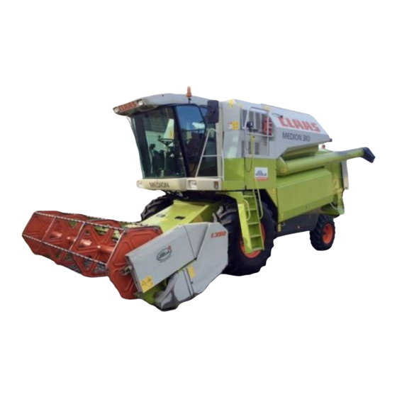
REPAIR
MANUAL
MEDION 340
MEDION 330
MEDION 320
MEDION 310

Advertisement

Table of Contents
loading

Summary of Contents for Claas MEDION 340

  • Page 1 REPAIR MANUAL MEDION 340 MEDION 330 MEDION 320 MEDION 310...
  • Page 2 Find manuals at http://best-manuals.com/search?&s=CLA-2992160...
  • Page 3 Installing the parking brake rope ........2.7.4 Air conditioner ................ 2.3.1 Removing the master cylinder ......... 2.7.6 Air conditioner – topping up refrigerant ......2.3.1 Installing the master cylinder ........... 2.7.6 0.1.1 299 216.0 - RHB MEDION 340 - 310 Find manuals at http://best-manuals.com/search?&s=CLA-2992160...
  • Page 4 Sieve pan ................4.4.1 Right threshing drum bearing, Removing the upper sieves ..........4.4.1 exploded view ..............3.3.16 Installing the upper sieves ..........4.4.1 Removing the lower sieves ..........4.4.1 0.1.2 RHB MEDION 340 - 310 - 299 216.0 Find manuals at http://best-manuals.com/search?&s=CLA-2992160...
  • Page 5 Removing the grain tank unloading tube ....... 5.3.18 Replacing the fan blades Installing the grain tank unloading tube ......5.3.19 (MEDION 330 – 310) ............. 4.8.27 Replacing the wear ring ..........5.3.21 0.1.3 299 216.0 - RHB MEDION 340 - 310 Find manuals at http://best-manuals.com/search?&s=CLA-2992160...
  • Page 6 Removing the threshing drum drive belt (24) ....7.3.8 Removing the threshing mechanism Installing and adjusting the threshing cylinder drive belt (5) ..............7.2.12 drive belt (24) ..............7.3.10 0.1.4 RHB MEDION 340 - 310 - 299 216.0 Find manuals at http://best-manuals.com/search?&s=CLA-2992160...
  • Page 7 Cutterbar drive slip clutch, exploded view ..... 7.6.20 Disassembling the threshing drum variable-speed Assembling the cutterbar drive slip clutch ..... 7.6.20 drive (spring-loaded) ............7.5.13 Installing the cutterbar drive slip clutch ......7.6.22 0.1.5 299 216.0 - RHB MEDION 340 - 310 Find manuals at http://best-manuals.com/search?&s=CLA-2992160...
  • Page 8 Fan variable-speed drive (electric), exploded view Straw chopper drive ............. 7.12.1 (MEDION 330 – 310) ............. 7.9.10 Removing the straw chopper intermediate drive jockey pulley ............7.12.1 0.1.6 RHB MEDION 340 - 310 - 299 216.0 Find manuals at http://best-manuals.com/search?&s=CLA-2992160...
  • Page 9 (MEDION 340) ............7.20.14 Removing the ground drive jockey pulley ...... 7.14.1 Assembling the axle drive Ground drive jockey pulley, exploded view ....7.14.1 (MEDION 340) ............7.20.16 0.1.7 299 216.0 - RHB MEDION 340 - 310 Find manuals at http://best-manuals.com/search?&s=CLA-2992160...
  • Page 10 MEDION 330 – 310) ............ 7.21.18 exploded view ..............9.5.4 Stub axle, exploded view Installing the low-pressure hydraulic system (adjustable rear axle – MEDION 340) ......7.21.18 solenoid valve ..............9.5.5 Installing the stub axles Removing the low-pressure hydraulic system (2.40 m rear axle / adjustable rear axle) ......
  • Page 11 CLAAS Auto-Contour flow control valve, hydraulic cylinder ............9.7.22 exploded view ..............9.6.35 Removing the 3-D cleaning system Installing the CLAAS Auto-Contour flow hydraulic cylinder ............9.7.22 control valve ..............9.6.36 0.1.9 299 216.0 - RHB MEDION 340 - 310...
  • Page 12 Disassembling the reverser drive Removing the charge air cooler ........10.4.8 hydraulic cylinder ............9.8.30 Installing the charge air cooler ........10.4.10 Reverser drive hydraulic cylinder, exploded view ..............9.8.31 11. Index 0.1.10 RHB MEDION 340 - 310 - 299 216.0...
  • Page 13: General Information

    General information...
  • Page 15 Introduction The present CLAAS REPAIR MANUAL is intended to assist in preserving the permanent operational readi- ness and therefore the high value of your CLAAS com- bine harvester by thorough maintenance and service supervision. Experience gathered by both our service engineers and factory staff has been compiled in this REPAIR MANUAL.
  • Page 16 This is the basis of safe and continued function following a repair. The table of contents of the main group / subgroup in question will allow you to locate any mechanical work description quickly. 1.1.2 RHB MEDION 340 - 310 - 299 216.0...
  • Page 17 Fill in, filler opening Mark Unlock, safeguard Overflow Safeguard, glue, seal Balance Vent with a liquid Reusable with Support, prop up reservations Replace with every Observe the direction assembly of installation 1.1.3 299 216.0 - RHB MEDION 340 - 310...
  • Page 18 General 1.1.4 RHB MEDION 340 - 310 - 299 216.0...
  • Page 19: Safety Rules

    (accident pre- vention). CLAAS is in no way liable for any damage or personal injury caused through the use of other than original or approved CLAAS parts, acces- sories and ancillary equipment.
  • Page 20: Intended Use

    12. Always blow the horn before starting the machine provide important information for safe engine and engaging the main drive. operation. These instructions involve your safety – observe them at all times! 1.2.2 RHB MEDION 340 - 310 - 299 216.0...
  • Page 21: Maintenance

    Accumulators are under high pressure! Compressor-type air conditioner With valve-controlled hydraulic accumulators – as for example on the CLAAS Autopilot – first slacken 1. The cooling system is filled with the short-circuit bolt before carrying out any repair FHC refrigerant R 134 A. FHC refrigerants work at the hydraulic accumulator.
  • Page 22 Safety rules 1.2.4 RHB MEDION 340 - 310 - 299 216.0...
  • Page 23: General Repair Instructions

    Blown bulbs must them completely. These self-locking bolts must not get therefore be replaced to ensure reliable field in contact with liquid sealing compound excitation. (e.g. omni FIT FD 10). 1.3.1 299 216.0 - RHB MEDION 340 - 310...
  • Page 24 (8.8/10.9 or similar) must be observed. Before inserting, apply some semi-fluid lubricant of NLGI class 00 (e.g. CLAAS semi-fluid lubricant EP 00, Self-locking bolts with micro-encapsulated adhesive part no. 147 455.1) to the inner ring and the shaft so...
  • Page 25 Attention! Any deviating tightening torques reduce the rated pressure resistance and the service life of the screw fitting. This results in leaks and the tube slipping out. 1.3.3 299 216.0 - RHB MEDION 340 - 310...
  • Page 26 – Replace split pins, locking wires, locking plates, tab washers and lock washers when carrying out repairs. – Insert greasable ball and sliding bearings with good grease. – Align sprockets and V-belt pulleys toward each other. 1.3.4 RHB MEDION 340 - 310 - 299 216.0...
  • Page 27: Torque Settings

    1200 M 27 x 2 1050 1500 1800 M 30 x 2 1450 2050 2500 Attention! Tighten cadmium-plated and copper-plated bolts and nuts only to torques 25% below the specified values. 1.4.1 299 216.0 - RHB MEDION 340 - 310...
  • Page 28 M 30 x 2 M 33 x 2 M 36 x 2 M 38 x 2 +103 M 39 x 2 +127 M 42 x 2 +147 M 45 x 2 1.4.2 RHB MEDION 340 - 310 - 299 216.0...
  • Page 29 M 45 x 1.5 M 48 x 1.5 M 48 x 2 M 52 x 1.5 M 54 x 2 With cadmium-plated threads, 0.7 times the values given in the table shall be applied. 1.4.3 299 216.0 - RHB MEDION 340 - 310...
  • Page 30: Wheel Bolts

    (special lock washers) = 325 Nm Rear drive axle Wheel bolts M 22 x 1.5 x 45 DIN 961-8.8 and spring washers C 22.5 DIN 74361 (special lock washer) = 520 Nm 1.4.4 RHB MEDION 340 - 310 - 299 216.0...
  • Page 31: Specifications

    Threshing drum reduction gearbox CLAAS Hypoid 1.0 litre transmission oil SAE 85W-90 API-GL-4 Multi-purpose trans- mission oil according to (MIL-L-2105) API-GL-4-90 specifications Foot brake ATE brake fluid DOT 4 Compensating tank filled 1.5.1 299 216.0 - RHB MEDION 340 - 310...
  • Page 32 <-25 °C (DIN ISO 3016) Viscosity 0 °C <600 cSt. (DIN 51 562) Viscosity 40 °C max. 50.6 cSt. (DIN 51 562) Viscosity index >170 (DIN ISO 2909) The oil must have detergent properties! 1.5.2 RHB MEDION 340 - 310 - 299 216.0...
  • Page 33 DC sheet 228.3 and 229.1 approx. 36.5 litres OM 906 LA 50 % anti-corrosion/antifreeze agent and 50 % water Perkins 1006.6 TA 50 % anti-corrosion/antifreeze approx. 46 litres agent and 50 % water 1.5.3 299 216.0 - RHB MEDION 340 - 310...
  • Page 34 Sharpening drive Lifting hydraulics ❋ Steering MEDION 320 approx. 25 approx. 20 Type 932 Low-pressure Sharpening drive Lifting hydraulics ❋ Steering MEDION 310 approx. 25 approx. 20 Type 932 Low-pressure Sharpening drive 1.5.4 RHB MEDION 340 - 310 - 299 216.0...
  • Page 35 50.6 cSt. (DIN 51 562) Viscosity index > 170 (DIN ISO 2909) The oil must have detergent properties! Note! The working and the ground drive hydraulics have one common hydraulic oil tank. 1.5.5 299 216.0 - RHB MEDION 340 - 310...
  • Page 36: Engine Data

    OM 906 LA 2200 1350±25 6370 2392 –30 136 (185) MEDION 310 Type 932 144 (196) Perkins 1006-6TA 2500 5985 1500 2600 –30 136 (185) * = max. engine speed without load 1.5.6 RHB MEDION 340 - 310 - 299 216.0...
  • Page 37: Operator's Platform

    Operator's platform...
  • Page 39 Remove the air inlet nozzles (E) on the left and right side. (Fig. 3) Unscrew the doors (F) from the hinge on the side panel on the left and right side. (Fig. 4) 2.1.1 299 216.0 - RHB MEDION 340 - 310...
  • Page 40 Unscrew four self-tapping screws at the front edge of the roof liner (L). (Fig. 7) Pull the front part of the roof liner (L) down carefully. Unscrew four hex. bolts from the top windscreen frame. (Fig. 8) 2.1.2 RHB MEDION 340 - 310 - 299 216.0...
  • Page 41 The windscreen must not be excessively pressed or pulled while removing it as it will otherwise suffer stress and may be destroyed. Wear gloves during the entire removal process. (Fig. 10, 11) 2.1.3 299 216.0 - RHB MEDION 340 - 310...
  • Page 42 3. Bolt down brackets (P) on the left and right side. (Fig. 12, 13) 4. Screw in four hex. bolts at the top windscreen frame. (Fig. 14) 2.1.4 RHB MEDION 340 - 310 - 299 216.0...
  • Page 43 6. Bolt down clamp (H) and hex. bolt (K). (Fig. 16) 7. Bolt down panel (G). (Fig. 17) 8. Bolt down the doors (F) to the hinge on the side panel on the left and right side. (Fig. 18) 2.1.5 299 216.0 - RHB MEDION 340 - 310...
  • Page 44 Removing the cab rear panel Unlock the operator's seat and pull it fully to the front. Fold away the seat back. On the left-hand side unscrew panel (A). Unscrew panels (B and C). (Fig. 22) 2.1.6 RHB MEDION 340 - 310 - 299 216.0...
  • Page 45 Two hex. bolts can be found at (G) beneath the insulation. (Fig. 24) Loosen locks (H) and rotate by 90°. Move flap (K) a little bit forward and then remove it. (Fig. 25) 2.1.7 299 216.0 - RHB MEDION 340 - 310...
  • Page 46 – Install the passenger seat (E). – Bolt down covering (D). (Fig. 23, 26, 27) 4. Bolt down panels (B and C). 5. Bolt down panel (A) on the left side. (Fig. 28) 2.1.8 RHB MEDION 340 - 310 - 299 216.0...
  • Page 47: Cab Heater

    Close the drain cock (B) tightly again after draining. (Fig. 3) Unlock the cab roof and fold it up. Unscrew cover (C) from the cab top. (Fig. 4) 2.2.1 299 216.0 - RHB MEDION 340 - 310...
  • Page 48 (K) and remove heater hoses. Collect any leaking cooling water. Environment! Dispose of cooling water in a way that is harmless to the environment and in accordance with existing anti-pollution regulations. (Fig. 7, 8) 2.2.2 RHB MEDION 340 - 310 - 299 216.0...
  • Page 49: Installing The Radiator

    1. Insert radiator (K) into cab top. 2. Bolt angle (L) to the cab side panel so that radiator (K) makes firm contact at (M and N). (Fig. 11) 2.2.3 299 216.0 - RHB MEDION 340 - 310...
  • Page 50 4. Bolt gas struts (D) down at the cab top on the left and right side at (E) with new lock nuts so that they have a little play. (Fig. 14) 5. Screw down cover (C) at the cab top. (Fig. 15) 2.2.4 RHB MEDION 340 - 310 - 299 216.0...
  • Page 51 This as a preview PDF file from best-manuals.com Download full PDF manual at best-manuals.com...

This manual is also suitable for:

Medion 330Medion 320Medion 310

Table of Contents