Compu-aire System 2100 Series Installation And Operation Manual
Glycol cooled energy miser
Hide thumbs
Also See for System 2100 Series:

Subscribe to Our Youtube Channel
Related Manuals for Compu-aire System 2100 Series


Summary of Contents for Compu-aire System 2100 Series
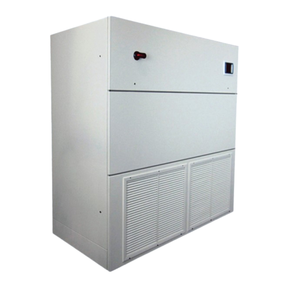
- Page 1 SYSTEM 2100 GLYCOL COOLED CAG-30 ENERGY MISER -INSTALLATION AND OPERATION MANUAL- 8167 Byron Road Whittier, CA 90606 Phone: (562) 945-8971 Fax: (562) 696-0724 www.compu-aire.com...
-
Page 2: Table Of Contents
TABLE OF CONTENTS SAFETY INFORMATION ....................5 CONTACTING COMPU-AIRE FOR TECHNICAL ASSISTANCE ........... 10 PRODUCT MODEL INFORMATION ................11 GENERAL EQUIPMENT DESCRIPTION ................. 12 RECEIPT OF UNIT AND TRANSPORTATION ..............13 TRANSPORTATION MODE .......................... 13 IMPORTANT – READ BEFORE INSTALLING ....................14 LOCATING THE UNIT .................... - Page 3 9.1.4 Dehumidification ......................... 25 9.1.5 Electric Panel ........................25 Steam Humidifier ............................25 Reheat ................................ 26 Condensate Pump (optional): ........................26 UNIT DIMENSIONS AND GENERAL COMPONENT LAYOUT........... 28 COMPONENTS IDENTIFICATION & ACCESS ..............29 11.1 FRONT LAYOUT (CONTROL BOX) ........................ 29 11.2 FRONT ACCESSS............................
- Page 4 Figure 8. Unit Dimensions-Standard Unit shown ..................28 Figure 9 Sample Unit Shown* ........................29 Figure 10. Condenser and Reheat elements access ................... 30 Figure 11. Unit Side Layout ......................... 30 Figure 12. Rear Open Floor Stand ....................... 31 Figure 13 - Terminal Block with System Cut-Out ..................32 Figure 14.
-
Page 5: Safety Information
This installation and operation manual (IOM) contains important safety information that should be followed during installation or servicing of a System 2100 series. Below is general safety information as well as descriptions of safety and accident prevention symbols that will be utilized throughout this document. - Page 6 DESCRIPTION OF IMPORTANT ACCIDENT PREVENTION SAFETY SYMBOLS SYMBOL DEFINITION Indicates an extremely hazardous situation which, if not avoided, will result in death or serious injury. Use of this symbol is limited to the most extreme situations Indicates a potentially hazardous situation which, if not avoided, could result in death or serious injury.
- Page 7 System 2100 Series equipment requires a permanent power connection from an isolated circuit breaker. The customer must provide earth ground to the unit per NEC, CEC, and local codes when applicable.
- Page 8 While every precaution has been made to ensure sharp edges, splinters, and exposed fasteners have been minimized internally and externally on the unit to prevent personal injury, it is highly recommended that all personnel installing or servicing the unit wear safety headgear, glasses, gloves, and shoes at all times.
- Page 9 severe property damage and loss of critical data center equipment. Suitable leak detection system should be installed inside or around the proximity of the unit to minimize any type of property damage. REFRIGERANT LEAKAGE DUE TO FREEZING TEMPERATURES AND/OR CORROSION Refrigerant leaking from the unit coil or piping due to freezing and/or corrosion can cause serious equipment and building damage.
-
Page 10: Contacting Compu-Aire For Technical Assistance
During usual business hour, you may call at (562) 945-8971 between 8:00am and 04:30pm, Pacific Time, Monday through Friday except holidays, or you may send a facsimile message at (562) 696-0724 anytime. Finally, you may write us at Compu-Aire, 8167 Byron Road, Whittier, CA 90606. -
Page 11: Product Model Information
HVAC equipment. Improper installation could result in unaccountable loss or damage. COMPU-AIRE System 2100 series equipment requires a permanent power connection from an isolated circuit breaker. Customer must provide earth ground to the unit per NEC, CEC and local codes as applicable. -
Page 12: General Equipment Description
Risk of leaking unit coil/or piping due to freezing and/or corrosion can cause equipment and building damage. 4 GENERAL EQUIPMENT DESCRIPTION The Compu-Aire System 2100 glycol cooled with energy miser series is a complete environmental control system, factory wired, tested, and specifically designed to provide temperature, humidity, and dust control for computer room installation. -
Page 13: Receipt Of Unit And Transportation
Optional articles such as jack-stand parts, condensate pump, and remote control panel are packaged separately. REPORT ANY DAMAGE TO THE CARRIER. COMPU-AIRE IS NOT RESPONSIBLE FOR FILING OF ANY CLAIMS. ALL NEEDED INSPECTION AND CLAIM FILING IS THE RESPONSIBILITY OF THE RECEIVER Figure 2 Transportation 5.1 TRANSPORTATION MODE... -
Page 14: Important - Read Before Installing
5.2 IMPORTANT – READ BEFORE INSTALLING Check the power supply. Voltage, frequency and phase must correspond to that specified on the unit nameplate. The power supply must be able to handle the additional load imposed by this equipment. 6 LOCATING THE UNIT Consult local building codes and National Code for special installation requirements. -
Page 15: Setting Of The Unit
Install unit on leveled solid floor that can support the unit weight and vibrations. Securely mount the unit with floor and brace it with wall if needed. Install the unit closer to the largest heat load. Air distribution is very important for proper unit operation. Air balancing is required to obtain design CFM at site. -
Page 16: Connections
6.2 Connections In connecting the unit, several items must be addressed. They are: 6.2.1 Structural Support The unit can be installed directly on the floor of on the raised floor without the need for any special support. The floor should be level. Gasket material should be placed between the bottom perimeter of the unit and the floor on the downflow unit to act as vibration isolator. -
Page 17: Water Connection
6.2.4 Water Connection Follow local and building codes for field piping installation. A close circuit dry fluid cooler is to be used. A pump package for field install by other is generally included in the system with separate cabinet unit. Provide a shut off valve in supply and return line for isolation. Refer to general unit dimension for location of piping connection access. -
Page 18: Figure 4 Typical Unit Field Piping Connection
Figure 4 Typical Unit Field Piping Connection... -
Page 19: Electrical Connection
Note: Glycol and water cooled units are designed for maximum of 150 psig water pressure. Higher pressure units are available; refer to unit nameplate. 6.2.5 Electrical Connection The unit is completely factory wired with self-contained controls. IMPORTANT - Before proceeding with the electrical connections, make certain that the volts, hertz and phase correspond to that specified on the unit rating plate. -
Page 20: Refrigerants
7 REFRIGERANTS 7.1 REFRIGERANT OIL CHARGE DO NOT MIX DIFFERENT TYPE OF REFRIGERANT ON THE SAME SYSTEM. For adding refrigerant oil please follows compressor manufacturer for the proper type of refrigerant oil used for the system. DO NOT MIX DIFERRENT TYPE REFRIGERANT OIL IN THE SAME SYSTEM OR COMPONENT FAILURE AND SYSTEM MALFUNCTION MAY OCCUR. -
Page 21: Liquid Charge
2) Remove all fuses including main fan and transformer fuses. 3) Connect the external transformer to the solenoid valves. 4) Evacuate the system in accordance with the following procedure: Connect the refrigeration gauges on circuits #1 & #2 at both the suction and discharge service valves. -
Page 22: Leak Testing
3) Start the compressors check the level in the sight glass. If the level has lowered, add additional Freon to maintain the sight clear. After charging is complete, reset the high pressure switch. Approximate charge required per circuit: As recommended by ASHRAE MANUAL. Total Charge = Basic Charge + Liquid Line Based on Hermetic and scroll Compressor Line and Refrigerated Liquid at 100F 7.1.4 Leak Testing... -
Page 23: General Wiring Diagram
8 GENERAL WIRING DIAGRAM... -
Page 24: Components Operation Guide And Maintenance
COMPONENTS OPERATION GUIDE AND MAINTENANCE HIGH-SPEED MOVING PARTS Risk of high-speed moving parts can cause injury or death. Disconnect all local and remote electric power supplies and make sure blowers have stopped rotating before performing service operations. Do not operate up-flow units without installing a supply air plenum, ductwork or protective guard over the blower openings. -
Page 25: Dehumidification
9.1.4 Dehumidification Dehumidification can be checked by setting the humidity setpoint for an RH 10% below room relative humidity. The compressor should come On. Return humidity setpoint to the desired humidity. 9.1.5 Electric Panel The electric panel should be inspected for any loose electrical connections 9.2 Steam Humidifier The steam humidifier on System 2100 system is the most advanced OEM steam humidifier and provides steady and reliable humidification using the same proven cylinder technology as Nortec’s... -
Page 26: Reheat
9.3 Reheat Unit is equipped with one of the following reheats: Electrical heating elements Hot Gas Hot Water Steam No reheat Check your unit for the kind of reheat it has. For type hot water and steam piping connections are required. -
Page 27: Figure 7 Condensate Pump Schematic
It is recommended to check the manufacturer’s literature for more detail of the dry fluid cooler prior the unit installation. PUMPS FOR CKG MODELS: These are shipped from Compu-Aire along with the air conditioners unit. Pump supplied are internally protected, but in many localities local codes require that a separate fused disconnect be provided. -
Page 28: Unit Dimensions And General Component Layout
10 UNIT DIMENSIONS AND GENERAL COMPONENT LAYOUT Figure 8. Unit Dimensions-Standard Unit shown... -
Page 29: Components Identification & Access
11 COMPONENTS IDENTIFICATION & ACCESS 11.1 FRONT LAYOUT (CONTROL BOX) Figure 9 Sample Unit Shown* *Actual unit may be different NUMBER NAME DISCONNECT SWITCH CONTACTORS MOTOR PROTECTORS MICROPROCESSOR CONTROLLER TRANSFORMERS... -
Page 30: Front Accesss
11.2 FRONT ACCESSS REHEAT ELEMENTS CW/GLYCOLM ODULATING PRESSURE VALVE REGULATING VALVE AIR FILTER SWITCH Figure 10. Condenser and Reheat elements access 11.3 SIDE LAYOUT Figure 11. Unit Side Layout HUMIDIFIER COMPRESSOR HOT GAS BYPASS VALVE, SOLENOIDS,ETC PIPING CONNECTION... -
Page 31: Standard Floor Stand
11.4 STANDARD FLOOR STAND Figure 12. Rear Open Floor Stand... -
Page 32: System Cut-Out Jumper For Emergency Shut-Down
12 SYSTEM CUT-OUT JUMPER FOR EMERGENCY SHUT-DOWN The unit is completely factory wired with self-contained controls to run without using external system cut-out. When external system cut-out is used, remove the jumper between terminal 5 and 6 and use NC dry contact of field provided system cut-out relay. Figure 13 - Terminal Block with System Cut-Out The system cut-out terminal on the terminals strip is for connection to a “panic button”... -
Page 33: Piping Connection Layout
If the unit is provided with sensing cable type leak detection system, use specific manual provided by the manufacturer to install the complete system. Alarm relay dry contact from sensing cable type leak detection system can be connected to the digital input for condensate alarm of unit controller. Use 24VAC power from the unit terminal block for this alarm input PIPING CONNECTION LAYOUT 14.1 WATER/GLYCOL LINE CONNECTION... -
Page 34: Start-Up And Test Procedure
“ON” position and then back to “OFF”. The blower motor with have started and it is therefore possible to determine rotation. On Compu-Aire units, the blower should be rotating in a CLOCKWISE direction in downflow units and COUNTERCLOCKWISE direction in upflow units, looking in the right side of the unit. -
Page 35: General Maintenance
Similar to the clogged filter switch, adjustment may be necessary for the no air flow switch(s). The loss of airflow switch is wired in the normally closed position to open on airflow and the dirty filter switch is wired to the normally open position and set to close with dirty filter. Adjustment can be made by removing the top cover and turning the dial to the proper pressure. - Page 36 (1) Check electrical components and tighten any loose connections. (2) Check all wiring and electrical insulators. (3) Check contactors to ensure proper operation and contact point for wear. (4) Check that fan motors (if applicable) are operational, ensure fan blades are tight and all mounting bolts are tight.
-
Page 37: Reference Documents
17 REFERENCE DOCUMENTS... -
Page 39: Troubleshooting Guide
18 TROUBLESHOOTING GUIDE Complaint Problem Symptom Action 1. System does not run. No 24VAC supply Power LED is not on. Check circuit breaker in voltage. system 24VAC circuit and reset if necessary. Check System cutout switch. Test for 24VAC at pins 1 and 2 of MCP. If no voltage check machine wiring. - Page 40 3 humidity dis-played to above have been the actual value. followed, contact Compu-Aire for further assistance. 5. System does not cool Control parameters are System seems to Refer to the section in or does not cool...
- Page 41 not set as expected. check that all parameters are set correctly. Compressor is not Display shows Determine cause of high running because of high compressor failure or low pressure failure or low pressure failure. alarm. Alarm LED is on. and remedy. Press Reset button on MCP.
- Page 42 correctly. Humidifier is on. Display shows the The heaters don't humidifier is operating. operate while the humidifier is on. Refer to the section, Environment Control Settings, and check that all control parameters are set correctly. DIP switches on MCP After setting a Refer to the section in are not set correctly.
- Page 43 5 years. Contact again, the set points are Compu-Aire for not as they were. assistance in replacing the battery. Excessive noise on the There has been a Random problems could power supply.
- Page 44 an earth ground. 11. System is on but, No air flow, fire stat, The display shows one The system is no-thing is operating. water on floor or smoke or more of these alarms automatic-ally shut The blower is off. detector alarm is and the Alarm LED is on.
-
Page 45: Part List
PART LIST Sub- Components Voltage/Ph/Hz Part Number Components R407C, Scroll Compressor 201-150-012 Expansion Valve 239-150-002 HP Switch, Manual Reset 236-214-001 LP Switch 236-101-001 Filter Drier 233-150-002 Sight Glass 232-005-001 460/3/60 EC Motor 208-500-156 Airflow Switch 222-100-202 Filters Merv-14 & Merv-8 220-516-254 220-116-252 Humifidifier... - Page 46 MCP-SYS 2200+3L 254-743-302 Touch Screen Display Temp/Hum Sensor 254-744-302 Connector Kit 254-743-302 NTC Sensor 254-445-002 Communication Card pCOnet BACnet OVER MS/TP 254-549-004 pCOWEB ETHERNET INTERFACE 254-549-003 LONWORKS ECHELON 254-649-010...
- Page 47 Date: We warranty this Compu-Aire, Inc. computer room unit to be free from defects in material and workmanship; our obligation being limited to repairing or replacing at our factory any part (except as noted below) within one year from the date of shipment to the original purchaser.
- Page 48 +1 (562) 696-0724 (Fax) While every precaution has been taken to ensure the accuracy and completeness of this literature, Compu-Aire assumes no responsibility and disclaims all liability for damages resulting from use of this information or for any errors or omissions.
Need help?
Do you have a question about the System 2100 Series and is the answer not in the manual?
Questions and answers