
Related Manuals for Compu-aire SYSTEM 2100


Summary of Contents for Compu-aire SYSTEM 2100
- Page 1 SYSTEM 2100 AIR COOLED CAA-6 TO 12 TON KOMPACT -INSTALLATION OPERATIONS AND MAINTENANCE MANUAL 8167 Byron Road Whittier, CA 90606 Phone: (562) 945-8971 Fax: (562) 696-0724 www.compu-aire.com...
-
Page 2: Table Of Contents
Table of Contents 1.0 CONTACTING COMPU-AIRE FOR TECHNICAL ASSISTANCE ..............4 2.0 PRODUCT MODEL INFORMATION......................5 3.0 GENERAL EQUIPMENT DESCRIPTION ....................7 4.0 RECEIPT OF UNIT AND TRANSPORTATION .................... 7 5.0 LOCATING THE UNIT ..........................8 6.0 UNIT DIMENSIONS ..........................10 Front Layout .......................... - Page 3 Figure 7: TERMINAL BLOCK W/ SYSTEM CUT-OUT ..................16 Figure 8: P-TRAP SCHEMATIC ........................18 Figure 9: DRAIN CONNECTION ........................19 Figure 10: AIR PRESSURE DIFFERENTIAL SWITCH ..................27 Figure 11: TYPICAL SCHEMATIC ........................40 Compu-Aire Rev. 01 Page 3 of 42 05/27/2016...
-
Page 4: Contacting Compu-Aire For Technical Assistance
CONTACTING COMPU-AIRE FOR TECHNICAL ASSISTANCE Compu-Aire, Inc. uses the latest in electronic and software technologies to develop some of the most reliable and cost efficient air conditioning systems in the world. Since many of our customer installations are sensitive to down time, we stock nearly all components for your system ready for same day shipment. -
Page 5: Product Model Information
HVAC equipment. Improper installation could result in unaccountable loss or damage. COMPU-AIRE System 2100 series equipment requires a permanent power connection from an isolated circuit breaker. Customer must provide earth ground to the unit per NEC, CEC and local codes as applicable. - Page 6 Suitable leak detection system shall be installed for the unit and water supply lines to minimize the damage. Risk of leaking unit coil/or piping due to freezing and/or corrosion can cause equipment and building damage. Compu-Aire Rev. 01 Page 6 of 42 05/27/2016...
-
Page 7: General Equipment Description
The Compu-Aire System 2100 air cooled Kompact series is a complete environmental control system, factory wired, tested, and specifically designed to provide temperature, humidity, and dust control for computer room installation. System 2100 is designed to provide precise temperature control by utilizing advanced digital and analog control via a programmable logic controller. -
Page 8: Locating The Unit
The location of the unit shall be selected based on air distribution in the room and service access requirement. System 2100 air cooled series units are available with two air flow configurations. The down flow units are used for raised floor applications. The up flow units with plenum or duct connection are available for rooms without raised floor. - Page 9 Do not operate up-flow units without installing a supply air plenum, ductwork or protective guard over the blower openings. Compu-Aire Rev. 01 Page 9 of 42 05/27/2016...
-
Page 10: Unit Dimensions
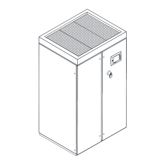
UNIT DIMENSIONS Figure 2: SYSTEM OVERVIEW Compu-Aire Rev. 01 Page 10 of 42 05/27/2016... -
Page 11: Front Layout
6.1 Front Layout Figure 3: FRONT VIEW LAYOUT NUMBER NAME COMPRESSORS EXPANSION VALVE ELECTRICAL COMPONENTS AND CONTROL PANEL BOX FRONT ACCESS PIPING CONNECTION FRONT ACCESS TO BLOWER MOTOR & HUMIDIFIER Table 1: SYSTEM COMPONENTS Compu-Aire Rev. 01 Page 11 of 42 05/27/2016... -
Page 12: Figure 4: High Voltage Control Panel Layout
High Voltage Control Panel Figure 4: CONTROL PANEL LAYOUT NUMBER NAME DISCONNECT SWITCH FUSES TRANSFORMERS MICROPROCESSOR CONTROLLER CONTACTOR TERMINAL BLOCK CONNECTION RELAY Table 2: CONTROL PANEL COMPONENTS Compu-Aire Rev. 01 Page 12 of 42 05/27/2016... -
Page 13: Sensors
AIR FLOW SWITCH Table 3: SMOKE DETECTOR 6.3 Low Voltage Control Panel Figure 5: LOW VOLTAGE CONTROL PANEL LAYOUT NUMBER NAME AUXILARY RELAY TERMINAL BLOCK PLC CONTROLLER Table 4: LOW VOLTAGE COMPONENTS Compu-Aire Rev. 01 Page 13 of 42 05/27/2016... -
Page 14: Refrigeration Components
6.4 Refrigeration Components Figure 4: UNIT LEFT ACCESS NUMBER NAME COMPRESSOR COIL BLOWER LIQUID RECEIVERS HOT GAS BYPASS VALVE SOLENOID VALVE FILTER DRIER PIPING CONNECTION ACCESS Table 4: REFRIGERATION COMPONENTS Compu-Aire Rev. 01 Page 14 of 42 05/27/2016... -
Page 15: Unit Left Access
6.5 Unit Left Access Figure 6 UNIT RIGHT ACCESS NUMBER NAME DIRTY FILTER STATIC PRESSURE TIP RETURN AIR TEMP/HUM SENSOR BLOWER MOTOR SUCTION ACCUMULATOR HUMIDIFIER Compu-Aire Rev. 01 Page 15 of 42 05/27/2016... -
Page 16: Remote Alarms
See controller guide for more detail on how to program this relay for selectable alarms. If unit is provided with extra relays, see unit wiring diagram and submittal for detail. Compu-Aire Rev. 01 Page 16 of 42... -
Page 17: Installation
The p-trap must be calculated as per below. After installation Figure 8: P-TRAP SCHEMATIC of the p-trap, verify trap operation by running the system blowers at full speed and Compu-Aire Rev. 01 Page 17 of 42 05/27/2016... -
Page 18: Piping
Primary drain line is provided with built-in trap. If the location of unit does not have provision to add external P-trap on secondary line, it must be capped-off. It is recommended that unions be installed in each line to permit Compu-Aire Rev. 01 Page 18 of 42... -
Page 19: Refrigeration Piping
It is of the greatest importance that all refrigerant piping be cleaned and free from dirt and moisture. One drop of water in a refrigerant system will greatly deter the operation and efficiency of the system. Upon installation, all open ends Compu-Aire Rev. 01 Page 19 of 42... -
Page 20: Evacuation Procedures
5) Check amperage on main fan and make sure it does not exceed FLA (full load amps). 6) Check fan rotation and correct if necessary. 7) Set thermostat at 40 8) Proceed with paragraph #4 in procedure #2. PROCEDURE FOR DEHYDRATION - METHOD #2 Compu-Aire Rev. 01 Page 20 of 42 05/27/2016... -
Page 21: Charging Procedure
8.7 Charging Procedure Turn the disconnect "ON" and check the evaporator fan for proper rotation. procedure. Connect the refrigerant gauges to the refrigerant drum purging the hoses to remove non-condesables. Compu-Aire Rev. 01 Page 21 of 42 05/27/2016... -
Page 22: Liquid Charge
1) After the dehydration procedures have been followed, replace the fuses in the condenser fan compressors and transformer circuits. 2) Connect hose from drum to suction port of the compressor, purge hose so that no non- condensables are in the hose. Compu-Aire Rev. 01 Page 22 of 42 05/27/2016... -
Page 23: Leak Testing
This includes water tubing, humidifier make-up water, and condensate lines (if provided). 8.11 How to Save the Refrigerant Charge The process of opening a refrigerant circuit of the Compu-Aire System 2100 and saving the refrigerant charge of the system to be opened requires only a few more minutes than does blowing the refrigerant charge. -
Page 24: Electrical Connection
SOURCE OF POWER SHOULD BE INTRODUCED AT THIS POINT. The conductors should be sized depending on the length of run and the number of control transformers used in the unit. Maximum voltage drop must not exceed 1 volt. Each control transformer draws Compu-Aire Rev. 01 Page 24 of 42... -
Page 25: Startup And Test Procedure
"OFF". The blower will have started and it is therefore possible to determine rotation. On Compu-Aire units, the blower should be rotating in a CLOCKWISE direction in the down flow units and COUNTER CLOCKWISE in the up flow units, looking in the right side of the unit. - Page 26 Adjustment can be made by removing the top cover and turning the dial to the proper pressure. See Figure 9 below. Compu-Aire Rev. 01 Page 26 of 42...
-
Page 27: General Maintenance
All doors to machine should remain closed before determining whether an adjustment is necessary. 2. Spare filters should be kept in stock. Filters should be checked monthly and replaced if necessary. Compu-Aire Rev. 01 Page 27 of 42 05/27/2016... -
Page 28: Trobleshouting Guide
Press Off button on MCP. shows erroneous MCP then press On characters or does button. If the system not change messages. does not start or if the display still shows erroneous information, replace the MCP. Compu-Aire Rev. 01 Page 28 of 42 05/27/2016... - Page 29 Check all wiring circuit board(s) are high or low values or between the sensor loose or broken. values that change circuit board and the erratically. MCP for loose connections. If the values Compu-Aire Rev. 01 Page 29 of 42 05/27/2016...
- Page 30 If tests are okay, swap connections between pins 14 and 16 and observe whether dis- play tracks each okay. If it does, replace the sensor. If it doesn't, replace the MCP. Compu-Aire Rev. 01 Page 30 of 42 05/27/2016...
- Page 31 3 above have humidity dis-played to been followed, the actual value. contact Compu-Aire for further assistance. 5. System does not Control parameters System seems to Refer to the section in cool or does not cool...
- Page 32 If no voltage at pin 27, check wiring back to 24VAC transformers in system. If voltage at pin 27 but not at 17, replace MCP. Compu-Aire Rev. 01 Page 32 of 42 05/27/2016...
- Page 33 Humidifier is on. Display shows the The heaters don't humidifier is operate while the operating. humidifier is on. Refer to the section, Environment Control Settings, and check Compu-Aire Rev. 01 Page 33 of 42 05/27/2016...
- Page 34 If no voltage at pin 27 or if voltage at each, check back to system terminal block and heater contactors. If voltage at pin 27 but, no voltage at pin 30 Compu-Aire Rev. 01 Page 34 of 42 05/27/2016...
- Page 35 Check all items under chilled water valve dehumidification but, 5 above. (depending on type compressors are not system) is not running or, for chilled operating. water systems, the valve is not open. Compu-Aire Rev. 01 Page 35 of 42 05/27/2016...
- Page 36 MCP has an expected control settings. and then turned on life of at least 5 years. again, the set points Contact Compu-Aire are not as they were. for assistance in replacing the battery. Excessive noise on the There has been a Random problems power supply.
- Page 37 Alarm down if any of these is activated. LED is on. conditions occur. Determine what the cause is and remedy. Then, press the Reset button on the MCP. Compu-Aire Rev. 01 Page 37 of 42 05/27/2016...
-
Page 38: Reference Documents
12.0 REFERENCE DOCUMENTS Compu-Aire Rev. 01 Page 38 of 42 05/27/2016... - Page 39 Compu-Aire Rev. 01 Page 39 of 42 05/27/2016...
-
Page 40: Figure 11: Typical Schematic
Figure 11: TYPICAL SCHEMATIC Compu-Aire Rev. 01 Page 40 of 42 05/27/2016... - Page 41 Date: We warranty this Compu-Aire, Inc. computer room unit to be free from defects in material and workmanship; our obligation being limited to repairing or replacing at our factory any part (except as noted below) within one year from the date of shipment to the original purchaser.
- Page 42 Whittier, CA 90606 While every precaution has been taken to ensure the accuracy and completeness of this literature, Compu-Aire assumes no responsibility and disclaims all liability for damages resulting from use of this information or for any errors or omissions.
Need help?
Do you have a question about the SYSTEM 2100 and is the answer not in the manual?
Questions and answers