Advertisement
Quick Links
xx
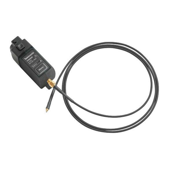
TPR1000 and TPR4000
Active Power Rail Probes
Compliance and Safety Instructions
1
*P071363700*
071-3637-00
Important Safety information
This manual contains information and warnings that must be
followed by the user for safe operation and to keep the product
in a safe condition.
To safely perform service on this product, additional
information is provided at the end of this section in the Service
safety summary.
General safety summary
Use the product only as specified. Review the following safety
precautions to avoid injury and prevent damage to this product
or any products connected to it. Carefully read all instructions.
Retain these instructions for future reference.
Probes and test leads
Before connecting probes or test leads, connect the power cord
from the power connector to a properly grounded power outlet.
Inspect the probe and accessories. Before each use, inspect
probe and accessories for damage (cuts, tears, or defects in
the probe body, accessories, or cable jacket). Do not use if
damaged.
High temperature probe tips
WARNING.
To prevent a burn injury, when using a solder
micro-coax or flex tip in a high temperature application, be
sure to allow the tip to cool down before handling the tip.
Service safety summary
The Service safety summary section contains additional
information required to safely perform service on the product.
Only qualified personnel should perform service procedures.
Read this Service safety summary and the General safety
summary before performing any service procedures.
Do not service alone. Do not perform internal service or
adjustments of this product unless another person capable of
rendering first aid and resuscitation is present.
x
Terms in this manual
These terms may appear in this manual:
WARNING.
Warning statements identify conditions or
practices that could result in injury or loss of life.
CAUTION.
Caution statements identify conditions or
practices that could result in damage to this product or
other property.
Symbols and terms on the product
When this symbol is marked on the product, be
sure to consult the manual to find out the nature of
the potential hazards and any actions which have
to be taken to avoid them. (This symbol may also
be used to refer the user to ratings in the manual.)
The following symbol(s) may appear on the product:
Compliance information
This product is intended for use by professionals and trained
personnel only; it is not designed for use in households or by
children.
Questions about the following compliance information may be
directed to the following address:
Tektronix, Inc.
PO Box 500, MS 19-045
Beaverton, OR 97077, USA
www.tek.com
Environmental considerations
This section provides information about the environmental
impact of the product.
Restriction of hazardous substances
Complies with RoHS2 Directive 2011/65/EU.
Product end-of-life handling
Observe the following guidelines when recycling an instrument
or component:
Equipment recycling. Production of this equipment required
the extraction and use of natural resources. The equipment may
contain substances that could be harmful to the environment or
human health if improperly handled at the product's end of life.
To avoid release of such substances into the environment and
to reduce the use of natural resources, we encourage you to
recycle this product in an appropriate system that will ensure
that most of the materials are reused or recycled appropriately.
This symbol indicates that this product complies
with the applicable European Union requirements
according to Directives 2012/19/EU and
2006/66/EC on waste electrical and electronic
equipment (WEEE) and batteries. For information
about recycling options, check the Tektronix Web
site (www.tek.com/productrecycling).
Operating overview
The TPR1000 and TPR4000 probes provide a low noise, large
offset range solution for measurement of ripple on DC power
rails ranging from –60 to +60 VDC and measurement of AC
ripple between 200 μV
and 1 V
at up to 4 GHz.
p-p
p-p
Refer to one of the following TPR1000 and TPR4000
Instruction Manuals for complete operating information and
product specifications. The manuals are available for download
at www.tek.com\downloads.
Language
Tektronix part number
English
077-1542-xx
Japanese
077-1543-xx
Simplified
077-1544-xx
Chinese
Environmental specifications
Specification
Description
Maximum input
DC: ±60 V
voltage
AC: ±30 V RMS
Pk-Pk: ±42 V peak
Temperature
Probe body: 0 to +55 °C
Standard accessories: –40 to +125 °C
High-temp accessories: –55 to +155 °C
Humidity
5 to 95% up to +40 °C, derate to 85% above
+40 °C
Altitude
0 to 3000 m
Key performance specifications
Specification
Description
Oscilloscope
6 series MSO, 5 series MSO,
compatibility
MSO/DPO3000, MDO/DPO4000,
MSO/DPO5000, DPO7000, and
DPO70000
1
oscilloscopes
Bandwidth in DC
TPR1000: DC to 1 GHz
coupling mode
2 3
TPR4000: DC to 4 GHz
Bandwidth in DC
TPR1000: 10 kHz to 1 GHz
reject mode
2 3
TPR4000: 10 kHz to 4 GHz
Linear dynamic
Up to 60 V DC, ±1 V
to bandwidth
p-p
range
Offset range
±60 V
Attenuation
1.25x
2
Measurement
DC linearity: <0.1%
accuracy
Step response long-term aberrations: ±1%
Noise
<300 μV
noise on 6 Series MSO (20 MHz
p-p
BW Limit)
<1 mV
noise on 6 Series MSO (Full
p-p
Bandwidth)
Input impedance
50 kΩ DC to 10 kHz
50 Ω AC > 100 kHz
Offset
±60 V offset range
Offset setting error: ±2 mV max, ±0.4 μV
typical
1
DPO70000 oscilloscopes require the optional TCA-VPI50 adapter.
2
Frequency response optimized for <1 Ω source impedance.
3
Through SMA-to-SMA cable or Solder Micro-Coax tip.
4
Max AC RMS of 1 V.
Standard accessories
Each probe is shipped with one TPR4KIT accessory kit
containing the following items:
e t I
m
D
s e
1.3 m cable, SMA male-to-MMCX
male, 50 Ω
1.3 m cable, SMA male-to-SMA male,
50 Ω
Y-lead adapter, MMCX
female-to-0.8 mm sockets
Adapter cable, MMCX female-to-U.FL
female, 50 Ω
Adapter, MMCX female-to-square pin
(0.062 centers)
DUT interface solder pins, set of 20
Soldering aide tool, 0.062 solder pins
over SMT
Solder-in cable adapter, MMCX
female-to-solder micro-coax tip, 50 Ω,
set of 3
Solder-in cable adapter, MMCX
female-to-solder flex-paddle tip, 50Ω,
set of 3
Wire card, solderable enameled
self-fluxing copper wire (for use with
the solder-in tips)
Probe tip tripod support (with living
hinge)
Marker bands, set of 5 (for probe
identification)
4
i r c
i t p
n o
Advertisement

Related Manuals for Tektronix TPR1000


Summary of Contents for Tektronix TPR1000
- Page 1 General safety summary Operating overview Use the product only as specified. Review the following safety The TPR1000 and TPR4000 probes provide a low noise, large DUT interface solder pins, set of 20 precautions to avoid injury and prevent damage to this product offset range solution for measurement of ripple on DC power or any products connected to it.
- Page 2 To achieve the best measurements results with a trimmed tip, refer to the TPR1000 and TPR4000 User Manual for guidelines and a description of best practices. Flex tip. To attach the solder flex tip, first solder the enameled Replacement 0.5 mm browser tips...
Need help?
Do you have a question about the TPR1000 and is the answer not in the manual?
Questions and answers