Tektronix TPR1000 User Manual
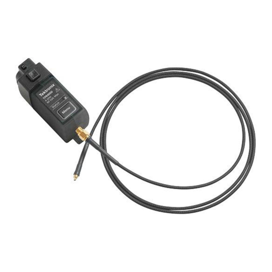
Active power rail probes
Hide thumbs
Also See for TPR1000:
- Compliance and safety instructions (2 pages) ,
- User manual (43 pages)

Subscribe to Our Youtube Channel
Related Manuals for Tektronix TPR1000


Summary of Contents for Tektronix TPR1000
- Page 1 TPR1000 and TPR4000 Active Power Rail Probes User Manual *P077154200* 077-1542-00...
- Page 3 TPR1000 and TPR4000 Active Power Rail Probes User Manual www.tek.com 077-1542-00...
- Page 4 Copyright © Tektronix. All rights reserved. Licensed software products are owned by Tektronix or its subsidiaries or suppliers, and are protected by national copyright laws and international treaty provisions. Tektronix products are covered by U.S. and foreign patents, issued and pending. Information in this publication supersedes that in all previously published material.
- Page 5 Warranty Tektronix warrants that this product will be free from defects in materials and workmanship for a period of one (1) year from the date of shipment. If any such product proves defective during this warranty period, Tektronix, at its option, either will repair the defective product without charge for parts and labor, or will provide a replacement in exchange for the defective product.
-
Page 7: Table Of Contents
Accessory characteristics..................... .. TPR1000 and TPR4000 User Manual... - Page 8 Cleaning ......................... Index TPR1000 and TPR4000 User Manual...
-
Page 9: Important Safety Information
Read this Service safety summary and the General safety summary before performing any service procedures. Do not service alone. Do not perform internal service or adjustments of this product unless another person capable of rendering first aid and resuscitation is present. TPR1000 and TPR4000 User Manual... -
Page 10: Terms In This Manual
(This symbol may also be used to refer the user to ratings in the manual.) The following symbol(s) may appear on the product: TPR1000 and TPR4000 User Manual... -
Page 11: Compliance Information
This symbol indicates that this product complies with the applicable European Union requirements according to Directives 2012/19/EU and 2006/66/EC on waste electrical and electronic equipment (WEEE) and batteries. For information about recycling options, check the Tektronix Web site (www.tek.com/productrecycling). TPR1000 and TPR4000 User Manual... -
Page 12: Preface
The following icon is used throughout this manual to indicate a step sequence. Returning the probe for servicing If your probe requires servicing, you must return the probe to Tektronix. If the original packaging is unfit for use or not available, use the following packaging guidelines: Preparation for shipment 1. -
Page 13: Why Use A Power-Rail Probe
(harmonics, faster ripples, etc.) on DC rails that could affect data signals, clocks, etc. The TPR1000 and TPR4000 provide a best-in-class solution for power integrity and validation engineers in the high speed (μP), low power (mobile) and switched-mode power supply markets. The probes are designed to offer the lowest noise with high bandwidth at 60 V offset, flexible connectivity options to cover customers challenges, and software packages to... -
Page 14: Key Features
Key features The TPR1000 and TPR4000 probes provide a low noise, large offset range solution for measurement of ripple on DC power rails ranging from –60 to +60 VDC. Tektronix’s power rail probes offer industry leading low noise and high offset range required to measure AC ripple between 200 μVp-p and 1 Vp-p at up to 4 GHz. -
Page 15: Installation
Installation Installation Operating considerations TPR1000 and TPR4000 power rail probe operating considerations. Table 1: Environmental characteristics Characteristic Description Temperature (comp box) Operating: 0 to +50 °C (+32 to +122 °F) Nonoperating: -20 to +85 °C (-4 to +185 °F) Temperature (standard accessories) Operating: -40 to +125 °C (-40 to +257 °F) -
Page 16: Connecting To The Host Instrument
A flashing green LED indicates that the probe is connected, but has not initialized. A red LED in any state indicates an error condition exists. (See page 35, Error condition.) TPR1000 and TPR4000 User Manual... - Page 17 1. Press the probe Menu button to display the Probe Control screen on the oscilloscope. 2. Short the probe tip to ground. 3. Press the AutoZero button on the instrument to execute the AutoZero routine. TPR1000 and TPR4000 User Manual...
-
Page 18: Functional Check
1. Connect the probe to the oscilloscope and a function generator as detailed in the connection diagram. (See Figure 1.) 2. If the function generator allows load impedance scaling, set the load impedance to high-Z. Otherwise, place a 50 Ω feed through terminator between the SMA cable and the probe. TPR1000 and TPR4000 User Manual... - Page 19 5. The instrument should show a 1 Vpp sine wave on the screen centered around 1 V. 6. Open the vertical channel menu and change the coupling mode to DC reject. 7. Set the vertical offset to 0 V. 8. Confirm that the signal is centered around 0 V. TPR1000 and TPR4000 User Manual...
-
Page 20: Basic Operation
The probe head amplifier used by the probe has a limited linear operating range. To keep the input linearity error within specification, you must limit the signal input voltage to ±1 V. Figure 2: Dynamic and Offset Limitations TPR1000 and TPR4000 User Manual... -
Page 21: Probe Offset
You can reuse a tip by removing the tip from the solder joint and then trimming the wire insulation back to expose the center pin and ground shield on the tip cable. TPR1000 and TPR4000 User Manual... -
Page 22: Using The Solder-Pin Installation Tool
3. If necessary, apply a small amount of adhesive to further strengthen the connection to the circuit board. However, keep the height of the adhesive to a minimum to provide good electrical contact for the adapter. TPR1000 and TPR4000 User Manual... -
Page 23: Using The Tripod
Alligator: Slide the ground lead prongs over the exposed metal between the plastic probe-tip sections. Blade: Locate the slot in the probe-tip housing as shown below. Slide the ground lead over the probe tip until the blade slides into the slot. TPR1000 and TPR4000 User Manual... - Page 24 To install a new browser-tip pin, select between a solid (silver colored) or spring-loaded (gold colored) pin, and then use pliers to gently insert the pin into the browser-tip housing until you feel the pin press against the bottom of the housing. TPR1000 and TPR4000 User Manual...
-
Page 25: Accessories And Options
1.3 m cable, SMA male-to-SMA male, 50 Ω Y-lead adapter, MMCX female-to-0.8 mm sockets Adapter cable, MMCX female-to-U.FL female, 50 Ω Adapter, MMCX female-to-square pin (0.062 centers) DUT interface solder pins, set of 20 Soldering aide tool, 0.062 solder pins over SMT TPR1000 and TPR4000 User Manual... -
Page 26: Optional Accessories
The optional TPR4KITHT high-temperature accessory kit includes the following items: Item 2 m high-temperature cable, SMA male-to-MMCX male, 50 Ω Solder-in cable adapter, MMCX female-to-solder micro-coax tip, 50 Ω, set of 3 Solder-in cable adapter, MMCX female-to-solder flex-paddle tip, 50 Ω, set of 3 TPR1000 and TPR4000 User Manual... - Page 27 Item Solder-in cable adapter, MMCX female-to-solder micro-coax tip, 50 Ω, set of 3 The optional TPR4SIAFLEX accessory kit includes the following items: Item Solder-in cable adapter, MMCX female-to-solder flex-paddle tip, 50 Ω, set of 3 TPR1000 and TPR4000 User Manual...
-
Page 28: Options
Option D5. Calibration Data Report, 5 years (with Option C5) Option R3. Repair Service 3 years Option R5. Repair Service 5 years Manual Options Option L0. English language Instruction Manual Option L5. Japanese language Instruction Manual Option L7. Simplified Chinese language Instruction Manual TPR1000 and TPR4000 User Manual... -
Page 29: Probing Principles
(See the illustration for the effects of lead length on waveform distortion.) The series inductance added by the probe tip and ground lead can result in a resonant circuit; this circuit may cause parasitic ringing within the bandwidth of your oscilloscope. TPR1000 and TPR4000 User Manual... -
Page 30: Ground Lead Inductance
The low-inductance ground contacts described in Accessories can help you reduce the effects of ground lead inductance on your measurements. TPR1000 and TPR4000 User Manual... -
Page 31: Specifications
The Signal Path Compensation (SPC) has been run on the oscilloscope before testing the probe specifications. Specifications for the TPR1000 and TPR4000 power rail probes fall into three categories: warranted, typical, and nominal characteristics. The warranted, typical, and mechanical characteristics apply to the TPR1000 and TPR4000 probes unless noted otherwise. -
Page 32: Typical Characteristics
Characteristic Description DC input resistance 50 kΩ Return loss Maximum: -12 dB between 10 MHz and 1 GHz (TPR1000) Maximum: -12 dB between 10 MHz and 4 GHz (TPR4000) 300 Hz DC to AC impedance crossover frequency DC to AC gain matching ±1%... - Page 33 Specifications Figure 3: TPR1000 frequency response Figure 4: TPR4000 frequency response TPR1000 and TPR4000 User Manual...
- Page 34 Specifications Figure 5: TPR1000 and TPR4000 input impedance and phase versus frequency Table 4: Probe typical mechanical characteristics Characteristic Description Dimensions, compensation box 85.1 mm × 40.6 mm × 30.5 mm (3.4 in × 1.6 in × 1.2 in) Packaged weight 1.24 kg (2.7 lbs)
-
Page 35: Nominal Characteristics
Insulation voltage rating ±30 V RMS (AC) ±42 V Peak (pk-pk) ±60 V DC (DC) Accessory characteristics Specifications for the TPR1000 and TPR4000 accessories fall into two categories: warranted and typical characteristics. Table 6: Accessory electrical characteristics Characteristic Description TPR4SIAFLEX and TPRSIACOAX... - Page 36 (typical) >2 GHz (TPR4000) TPR4BRWSR1G (typical) >350 MHz with short ground TPR4BRWSR1G (typical) 1 GHz with barrel adapter Table 7: Accessory typical mechanical characteristics Item number Dimensions Rigid Browser Pogo Browser Browser Browser Spring Ground TPR1000 and TPR4000 User Manual...
- Page 37 Specifications Table 7: Accessory typical mechanical characteristics (cont.) Item number Dimensions Browser Blade Ground Browser Alligator Ground TPRSIACOAX TPRSIAFLEX MMCX to U.FL adapter TPR1000 and TPR4000 User Manual...
- Page 38 Specifications Table 7: Accessory typical mechanical characteristics (cont.) Item number Dimensions 1.3 m SMA to MMCX Cable 1.3 m SMA to SMA Cable 2 m SMA to MMCX Cable Browser to Square-pin adapter TPR1000 and TPR4000 User Manual...
- Page 39 Specifications Table 7: Accessory typical mechanical characteristics (cont.) Item number Dimensions MMCX to Square-pin adapter Component Clip TPR1000 and TPR4000 User Manual...
-
Page 40: Performance Verification
N to SMA-M 5 foot cable 012-1774-XX SMA adapter for network analyzer Type-N male to Type-SMA female 013-0406-XX SMA torque wrench 5/16-in, 7 in-lb. SMA adapter wrench 7/32-in Nine-digit part numbers (xxx-xxxx-xx) are Tektronix part numbers. TPR1000 and TPR4000 User Manual... -
Page 41: Equipment Setup
Use the DC setup diagram for the following performance checks. DC gain accuracy (See page 29.) DC input dynamic range (See page 31.) Input offset range and scale accuracy (See page 32.) Figure 6: DC setup connection diagram TPR1000 and TPR4000 User Manual... - Page 42 Performance verification Analyzer setup connection diagram Use the analyzer setup diagram for the analog bandwidth performance check. (See page 33.) Figure 7: Analyzer setup connection diagram TPR1000 and TPR4000 User Manual...
-
Page 43: Check The Dc Gain Accuracy
–256 mV 0 mV 0 mV 320 mV 256 mV 640 mV 512 mV 10. Repeat steps 8 and 9 for each voltage level listed in the table. (See page 30, DC gain measurement example.) TPR1000 and TPR4000 User Manual... - Page 44 (rise in Y divided by run in X), and the zero point error taken at the point at which the line crosses the Y axis. The DC output value can be predicted by the following equation: 3. The following table shows the measured gain as calculated from the slopes of the plotted measured values. TPR1000 and TPR4000 User Manual...
-
Page 45: Check The Dc Input Dynamic Range
16. Ensure that output does not shift by more than 0.01 V during the test. Result is reported as Pass or Fail. 17. Return the probe to DC Coupling mode. 18. Record the result in the test record. (See page 34.) TPR1000 and TPR4000 User Manual... -
Page 46: Check The Input Offset Range And Scale Accuracy
DC source voltage Probe vertical offset setting +12 V +12 V +1 V +1 V –1 V –1 V –12 V –12 V 8. Record the result of each setting in the test record. (See page 34.) TPR1000 and TPR4000 User Manual... -
Page 47: Check The Analog Bandwidth
4. Place a marker on the S21 trace at the start frequency (300 kHz). 5. Place a marker on the S21 trace at the probe bandwidth (1 GHz for TPR1000 or 4 GHz for TPR4000). 6. Verify that the amplitude is greater than -3.97 dB (subtracting the 0.97 dB of probe attenuation range from the 3.97 dB target value yields the 3 dB limit). -
Page 48: Test Record
-194 mV 194 mV +12 V offset -18 mV 18 mV +1 V offset –1 V offset -194 mV 194 mV –12 V offset -18 mV 18 mV Analog bandwidth -3 dB TPR1000 -3 dB TPR4000 TPR1000 and TPR4000 User Manual... -
Page 49: Maintenance
This section contains maintenance information for your probe. Error condition The TPR1000 and TPR4000 power rail probes are designed to work with all TekVPI-interface oscilloscopes and adapters. However, there may be some cases where all of the probe features may not work properly. - Page 50 Maintenance TPR1000 and TPR4000 User Manual...
-
Page 51: Index
TekVPI, 2 Maintenance, 35 Test record, 34 DC gain accuracy Menu Button, 3 performance check, 29 DC input dynamic range performance check, 31 Documentation, vi Offset, 7 Operating considerations, 1 Options, 14 Error condition, 35 TPR1000 and TPR4000 User Manual...
Need help?
Do you have a question about the TPR1000 and is the answer not in the manual?
Questions and answers