Table of Contents
Advertisement
Advertisement
Table of Contents

Subscribe to Our Youtube Channel
Related Manuals for Giada PC68


Summary of Contents for Giada PC68
- Page 1 - 1 -...
- Page 2 The copyright of this manual belongs to Shenzhen JEHE Technology Development Co., Ltd. (Giada, JEHE’s global brand) and all rights are reserved. The company reserves the right to change this manual at any time without notification. Specifications here are for reference only, please take the real product as standard.
-
Page 3: Table Of Contents
Table of Contents 1. Product Introduction ..................5 2. Interface Description and Hardware Specifications ........6 2.1 Interface Description .................. 6 2.2 Hardware Specifications ................6 3. Accessories Installation Steps ................. 7 3.1 CPU Installation ................... 7 3.2 Memory Installation ..................9 3.3 SSD (M.2) Installation ................. - Page 4 4.2.8 CSM Configuration ................25 4.3 Chipset ......................26 4.3.1 System Agent (SA) Configuration ............ 27 4.3.1.1 Memory Configuration ............28 4.3.1.2 Graphics Configuration ............29 4.3.2 PCH-IO Configuration ..............30 4.3.3 SATA and RST Configuration ............32 4.3.4 USB Configuration ................33 4.4 Security ......................
-
Page 5: Product Introduction
Complies with Intel OPS standards and based on Intel ® Coffee Lake platform, Giada PC68 adopts DDR4 dual-channel memory (Max 32GB) as well as M.2 storage interface design. With selectable desktop processors, it provides high computing and graphics performance. The player is suitable to be applied in interactive white board, video conference and other high-end digital signage applications. -
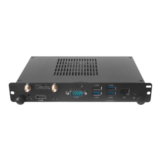
Page 6: Interface Description And Hardware Specifications
2.2 Hardware Specifications PC68 Intel ® LGA1151 Socket 8 Gen. Processor Processor BIOS AMI Source Code ® Chipset Intel H310C/Q370/B360 Type DDR4-2400MHz Memory Socket 2 x SO-DIMM Max Capacity 32 GB 1 x DP (JAE) (Max.4096 x 2304@60Hz) 1 x HDMI (JAE) Graphics (Max.4096 x 2304@60Hz(H310C) -
Page 7: Accessories Installation Steps
3. Accessories Installation Steps For safety reasons, please ensure that the power is disconnected before opening the case. How to open the top cover and bottom cover Unscrew the seven screws and remove the top cover. (CPU, SO-DIMM #1 and M.2 for WIFI are on top side) Unscrew the three screws and remove the two covers. -
Page 8: Memory Installation
3.2 Memory Installation This product only supports DDR4 SO-DIMM memory modules. 1. Locate the SO-DIMM slot on the board. 2. Gently insert the module into the slot in a 45-degree angle. 3. Carefully push down the memory module until it snaps into the locking mechanism. - 8 -... -
Page 9: Ssd (M.2) Installation
3.3 SSD (M.2) Installation 1. Plug the SSD (M.2) into the appropriate slot. 2. Secure the module to the carrier by tightening up the screw. 3. Remove the clear membrane of the thermal pad and paste the pad on the SSD. 4. -
Page 10: Wifi (M.2) Installation
3.4 WIFI (M.2) Installation 1. Plug the WIFI module into the appropriate slot. 2. Secure the module to the carrier by tightening up the screw. 3. Connect the two black cables to Main and AUX. Install antennas. Hot-plugging may cause damage to the OPS PC. Please disconnect the power of the monitor before installing the OPS PC into the slot. -
Page 11: Bios Setup
The descriptions relating to BIOS setup in this Manual is for reference only since the BIOS version of the product might be upgraded. Giada provides no guarantee that all the contents in this Manual are consistent with the information you acquired. - Page 12 B. Function Keys definitions Hot Key Description ↑ (Up key) Move to the previous item ↓ (Down key) Move to the next item ← (Left key) Move to the left item → (Right key) Move to the right item Exit the current interface Page Up Change the setup state, or add the values Page Down...
- Page 13 Fig 1 1) Main (standard CMOS setup) This item is used for setting the date and time. 2) Advanced (advanced BIOS setup) This item is used for setting the advanced functions provided by BIOS, such as specifications of PCIe facilities, CPU, HDD, etc.
-
Page 14: Main (Standard Cmos Setup)
4.1 Main (Standard CMOS Setup) 1) System time (hh:mm:ss) Use this item to set the time for the computer, with the format as “HH / MM / SS”. 2) System date (mm:dd:yy) Use this item to set the date for the computer, with the format as “week, MM / DD / YY”. - 14 -... -
Page 15: Advanced (Advanced Bios Setup)
4.2 Advanced (Advanced BIOS Setup) 4.2.1 Power & Performance - 15 -... - Page 16 Power & Description Performance L1 Instruction Cache L1 Instruction Cache. L2 Cache L2 Instruction Cache. VirtualMachineExtension. SMX/TXT Intel trusted execution. VT-d Intel ® Virtualization Technology for Directed I/O. Max Non-Turbo Performance: the best performance. Boot performance Max Battery. mode ...
-
Page 17: Oem Configuration
4.2.2 OEM Configuration The menu Description OEM Configuration The user can enable or disable WDT function. Disabled: WDT item is disabled by default Watchdog Time Support Minute: second: The user can set output signal as DP or HDMI. DP is set by default. -
Page 18: Oem Me Configuration
4.2.3 OEM ME Configuration Advanced Options Description ME Configuration This item can enable or disable ME function ME Control Disabled Enabled. The ME control is enabled by default. - 18 -... -
Page 19: Pc Hardware Monitor Status
4.2.4 PC Hardware Monitor Status Advanced Options Description PC Hardware Monitor Status It includes " Full on mode ", " Smart Fan " " manual mode ". Full on mode. Smart Fan Fun ction Smart Fan: Smart Fan is enabled by default. ... -
Page 20: Wake Configuration
1 PWM PWM slope setting 2 PWM 4 PWM CPU TEMP Current CPU Temperature. SYS TEMP Current System Temperature. CPU FAN Current FAN Speed. VCORE VCORE Voltage. VDIMM VDIMM Voltage. 4.2.5 Wake Configuration Advanced Options Description Wake Configuration - 20 -... -
Page 21: Usb Configuration
Enable or disable System wake on alarm event. Select FixedTime, system will wake on the hr::min::sec Resume On RTC specified. Select DynamicTime, System will wake on the current time + Increase minute(s). Enabled or Disabled Wake Up by USB KB/MOUSE from S3 Status. - Page 22 USB Configuration Description USB Configuration USB Module Version This item can show USB module version. USB Controllers The current USB Controllers. USB Devices The current USB devices. You can set and manage legacy USB device after enabling this option. Disabled.
-
Page 23: Network Stack Configuration
USB Configuration Description Maximum time the device will take before it properly reports itself to the Host Controller. Auto uses default value: for a root port, it is 100ms; for a Hub Device power-up delay port, the delay is taken from Hub descriptor. ... - Page 24 Advanced options Functions Description Enabled. Disabled. This item is disabled by default. Enabled/Disabled IPV6 PXE boot support. Ipv6 PXE Support Enabled. Disabled. This item is disabled by default. Enabled/Disabled IPV6 HTTP boot support. Enabled. Ipv6 HTTP Support ...
-
Page 25: Csm Configuration
4.2.8 CSM Configuration Advanced Options Description Compatibility Support Module Configuration Enabled: The CSM support function is enable by default. CSM Support Disabled. UFEI and Legacy: It will support both UEFI and legacy mode. Boot option filter Legacy only: It only supports legacy mode. -
Page 26: Chipset
Advanced Options Description Video ROM Boot. Video UEFI: It will support UEFI mode Video ROM. Legacy: It will support Legacy mode Video ROM. Do not launch: Do not Boot. Other PCI devices UEFI: It will support UEFI mode PCI ROM. Legacy: It will support Legacy mode PCI ROM. -
Page 27: System Agent (Sa) Configuration
4.3.1 System Agent (SA) Configuration Chipset Option Description System Agent (SA) Configuration Enabled/Disabled above 4GB memoryMappedIO BIOS assignment. This is enabled automatically when Aperture size is set to 2048MB. Above 4G MMIO BIOS Disabled. assignment Enabled. This item is enabled by default. - 27 -... -
Page 28: Memory Configuration
4.3.1.1 Memory Configuration Chipset Options Description Memory Configuration Memory Frequency Memory Frequency Memory Memory Timings Timings(tCL-tRCD-tRP-tR Channel 0 slot 0 Channel 0 slot 0 Channel 1 slot 0 Channel 1 slot 0 The user can set the maximum memory frequency. This item is Maximum Memory Frequency auto by default. -
Page 29: Graphics Configuration
4.3.1.2 Graphics Configuration Chipset Options Description Graphics Configuration Graphics Turbo IMON Graphics turbo IMON current value supported (14-31). Current GTT Size 8M. This item is 8M by default. Note: Above 4GB MMIO BIOS assignment is automatically enabled when selecting 2048MB aperture. -
Page 30: Pch-Io Configuration
Chipset Options Description Select DVMT 5.0 Pre-Allocated (Fixed) Graphics Memory size used DVMT Pre-Allocated by the internal graphics device. Select DVMT5.0 total graphics size used by the internal graphics device 256M.This item is 256M by default. DVMT Total Gfx Mem ... - Page 31 Chipset Options Description PCH-IO Configuration Specify what state to go to when power is re-applied after a power failure (G3 state) State after G3 means after restore power supply. Power off: If set it as power off, it means the system will remain shutdown state.
-
Page 32: Sata And Rst Configuration
4.3.3 SATA and RST Configuration Chipset Options Description SATA And RST Configuration Enabled/disabled SATA Controller. SATA Controller(s) Disabled. Enabled: The SATA controller is enabled by default. AHCI: AHCI mode. SATA Mode Selection Intel RST Premium With Intel Optane System Acceleration: IRST mode. -
Page 33: Usb Configuration
Chipset Options Description M.2 Device M.2 interface information. 4.3.4 USB Configuration Chipset Options Description USB Configuration Options to disable compliance mode. Default is FALSE to not disable compliance Mode. Set TRUE to disable Compliance Mode. XHCI Disable Compliance Mode TRUE. -
Page 34: Security
4.4 Security If this function is selected, the following information will appear: Enter New Password hhhhhh Then enter a password which is no more than eight characters and press <Enter>. BIOS will require to enter the password again. Once you enter it again, BIOS will save the set password. Once the password item is enabled, you will be required to enter the password every time before the system entering to the setup program of BIOS. -
Page 35: Boot Menu
4.5 Boot Menu Boot Item Description Boot Configuration This item is use to set the wait time of entering the operation system. During the BIOS post, if user doesn't press the keyboard, Setup Prompt Timeout it won't respond unless you reboot the BIOS. The Setup Prompt Timeout is 3s by default. -
Page 36: Save & Exit
Boot Item Description You can set and manage legacy Hard disk device after enabling Hard Drive BBS Priorities this option. 4.6 Save & Exit Save Exit Item Description Save Options Save Changes and Reset Save all changes and exit Discard Changes and Reset Give up the settings and exit. - Page 37 - 37 -...
Need help?
Do you have a question about the PC68 and is the answer not in the manual?
Questions and answers