Table of Contents
Advertisement
Quick Links
Installation and mounting manual for EK-FB KIT GA P67A (UD7) water block:
This product is intended for installation only by expert users. Please consult with a qualified technician for installation. Improper installation may result in damage to your equipment. EK Water Blocks assumes no liability
whatsoever, expressed or implied, for the use of these products, nor their installation. The following instructions are subject to change without notice. Please visit our web site at
Before installation of this product please read important notice, disclosure and warranty conditions printed on the back of the box.
The barb hose fittings require only a small amount of force to screw them in; otherwise the high flow fittings might break. These fittings do not need to be tightened with much force because the
liquid seal is made using o-rings.
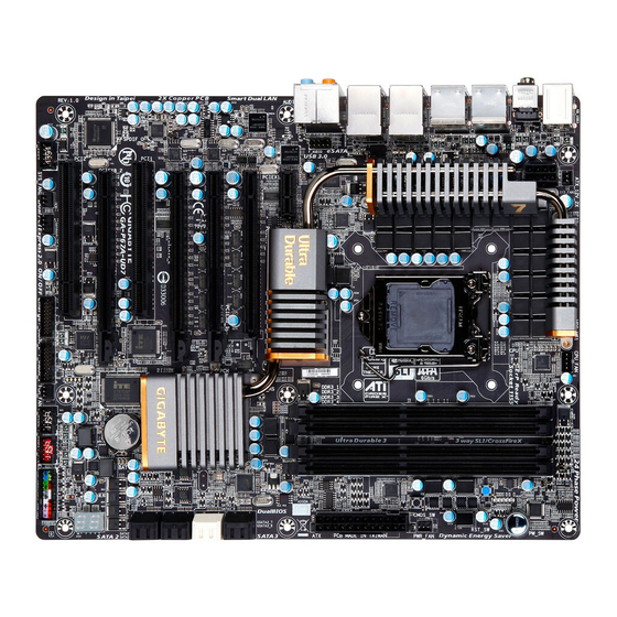
STEP 1: GENERAL INFORMATION Sample photo of GIGABYTE GA-P67A-UD7 / GA-P67A-UD7-B3 PCB design
STEP 2: PREPARING YOUR MOTHERBOARD
1. REMOVING STOCK COOLER.
pipe cooler assembly to the motherboard's circuit board.
3. APPLYING THERMAL COMPOUND
Apply thermal compound: lightly coat the NF200 (NB) and P67 PCH (SB chips with
- for example Arctic Cooling MX2 ™, MX3 ™ or MX4 ™ - thermal compound.
Follow this link:
http://www.arctic-cooling.com/catalog/images/install_mx2_retail.pdf
instructions. EKWB recommends to apply thermal grease in cross form (see
sample picture).
5. PLACING THERMAL PADS ON MOTHERBOARD.
BOTH SIDES PRIOR TO INSTALLATION.)
Apply thermal grease on
Northbridge (NF200) and
Southbridge (P67).
All disclosures, notices and warranty conditions are being written on the back of the box.
NF200
bridge chip
P67 Southbridge
Remove all 10 screws holding the original heat-
Place thermal pads you cut on PCB as shown on picture bellow.
Place 1.5mm
thermal pads here
2. CLEANING THE PCB.
screws securing it to the board. Wipe off the remains (by using non–abrasive cloth or qtip,
as shown on sample photo) of the original thermal compound until the components and
circuit board are completely clean. EKWB does not recommend using any liquids for
removing paste.
4. CUTTING THERMAL PADS.
20x20x1.5mm - are enclosed with your water block kit. You will have to cut out small chunk
from one thermal pad in order to cover all marked surfaces surface. (WARNING:
DIMENSIONS ON PICTURES BELLOW ARE SCALED!)
for detailed
1.5mm
Place 1mm thermal pads here and make
sure all chips are covered.
Mosfets
CPU socket
Carefully detach the original stock cooler after removing all
Three thermal pads - two 90x15x1 mm and one
1mm
(PLEASE REMOVE FOIL OF THERMAL PADS ON
Released on 11
www.ekwaterblocks.com
for updates.
th
of January, 2011.
Advertisement
Table of Contents

Related Manuals for ekwb EK-FB KIT GA P67A UD7


Summary of Contents for ekwb EK-FB KIT GA P67A UD7
- Page 1 Wipe off the remains (by using non–abrasive cloth or qtip, as shown on sample photo) of the original thermal compound until the components and circuit board are completely clean. EKWB does not recommend using any liquids for removing paste.
- Page 2 STEP 3: PREPARING YOUR WATER BLOCK 1. ATTACHING STANDOFFS. Apply small amount of thermal grease around mounting 2. PLACING BLOCK OVER MB. Place the motherboard on the inverted water blocks holes and place acetal standoffs on NB/SB block (thickness 2,1 mm) so the holes are or vice versa and attach them with enclosed screws as shown.
Need help?
Do you have a question about the EK-FB KIT GA P67A UD7 and is the answer not in the manual?
Questions and answers