Advertisement
Quick Links
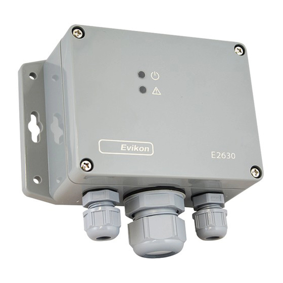
E2630 series gas detectors are compact and easy-to-use instruments.
The devices utilise novel fully calibrated and temperature compensated gas
sensors with excellent repeatability, stability and long lifetime.
Two relays RE1 and RE2 with switching contacts can be used to control alarm
sirens, ventilation fans, shut-off valves or other actuators. The devices are
equipped with visual and acoustic alarm.
The version of your detector is marked on the package.
Safety requirements
Always adhere to the safety provisions applicable in the country of use.
Do not perform any maintenance operation with the power on. Do not let water or
foreign objects inside the device.
Operating and storage conditions
• The device should be used in explosion-safe (non ATEX -rated) indoor areas at
the atmospheric pressure ±10% and RH 15...95 % without condensation
• Avoid exposure to highly corrosive gases (H
S, SO
2
concentrations of basic gases, such as ammonia.
• Avoid mechanical shock or strong vibrations.
• Avoid sources of electromagnetic interference
• See Specifications table for more details
When stored without powering in normal air for a long period, or in an environment
contaminated with organic vapors or volatile oils, the sensor may show a reversible
drift in resistance according to the environment.
Mounting dimensions
145
130
115
30
M 6
1
E 2630
M25
Installation
There are no precise rules or standards to follow when installing the gas detectors. The
following points must be taken into account:
application (air quality control or leakage detection),
properties of the space under investigation (room geometry, direction and velocity of
air flows etc),
detected gas (relative density to air, whether the gas is flammable, or toxiс, or oxygen
displacing),
safety: strong vibrations, mechanical shock, and the sources of strong
electromagnetic interference should be avoided,
the device should be accessible for maintenance and repair.
For early leakage detection install the sensor as close as possible to the potential
leakage sources (flanges, valves, pressure reducers, pumps, etc), taking into
consideration other points listed above. Do not locate the detector close to ventilation
openings and strong air currents. Avoid the areas without air circulation (corners,
niches) as well. For general area monitoring without definite leakage sources, the
detectors should be distributed evenly in the room. For personal safety control the
detectors are installed in the breathing zone (at the height of the head of people or
animals). Recommended sensor position is vertical, pointing downwards. See
Installation guidelines section for more information.
The device is mounted on the wall using four round holes or two key slots (see
dimensional drawing in the previous section).
Connections
1. Unscrew four lid screws and detach the the front from the device.
2. Attach the device to the wall. (This step may be done after the step 3, consider
your convenience).
3. Use two M16 cable glands to let in the cables of the power supply and of the
external devices.
Connect the power terminals N and L to the 24 V AC/DC source if you are using
, HCl, Cl
etc), or high
2
2
detector version -24 or to 230 VAC mains if you are using detector version -230
(see diagram below).
The terminals on the E2630 series devices are suitable for a wide range of wires
with cross-section 0,2...1,5 mm2. We recommend to strip the wire end by 5...6 mm
and use the wire end sleeves. To connect wire, loosen the screw, insert the wire
end into terminal hole and tighten the screw.
To use relay outputs, connect the chosen actuators to the relay terminals RE1
and/or RE2.
NB! Actuator short-circuits shall be avoided, to protect the instrument relays use
external fuses or safety switches.
4. Place the lid back and fix it with the screws. Make certain that the cable glands
5 5
are properly tightened to ensure the conformity to IP65 protection class.
5 Turn on the power. It may take up to five minutes after switching on for the sensor
to stabilize.
For stable operating it is recommended to keep the detector powered constantly,
except for periods of maintenance and calibration, deplacement etc.
Operating. Alarm release mode
During the first ca. 60 seconds after powering on E2630 performs a warming-up
and self-diagnostic routine, indicated by the flashing of each LED. The upper dual-
color LED remains continuously green in normal operation and blinks red in case of
device or sensor fault. The warm-up time depends on the sensor type, unpowered
period and atmosphere.
During the first 30 seconds after powering on you may select automatic or manual
mode of alarm release. Touch the device with the magnet key on the spot shown at
the drawing below. A short touch (< 2 s) enables the automatic mode, a touch of
2...10 s — manual mode. The activation of the automatic mode is followed by a
single LED blinking and acoustic signal. If manual mode is activated, double
acoustic and light signal follows.
If gas concentration exceeds the LOW alarm setpoint, the bottom red LED starts
flashing at a rate of 1 Hz, and the relay RE1 switches over. The first alarm stops
automatically if the gas concentration drops below 80% of the LOW alarm setpoint.
If gas level exceeds the HIGH alarm setpoint, the bottom red LED starts flashing
and the buzzer starts beeping at a rate of 2 Hz, and also the relay RE2 switches
over. Depending on the selected release mode, the HIGH alarm stops automatically
or can be stopped with a short touch of the magnet key, if the gas level has dropped
below 80% of the LOW alarm setpoint. Upon contact the key should activate the
reed switch located left of the sensor inside the device.
Magnet
Apart from the warming-up period, a 2....10 s touch causes the device to reset and
perform the self-diagnostic routine for testing purposes.
To check the visual and acoustic alarm, touch the device with the magnet key for
more than 10 s. This will launch blinking and beeping (stops as soon as the key is
withdrawn).
Sensor probe handling
The E2630 series detectors are available with remote probe (see drawing below for
dimensions). The remote probe is connected to the main unit with shielded cable.
Default connection cable length is 3 m. The sensor probes of all types are equipped with
a hydrophobic microporous PTFE filter to protect the sensor from dust, dirt and water
drops. The filter may be replaced if it gets strongly contaminated. To replace the PTFE
filter, unscrew the M25 nut and remove the old filter. Place a new filter into the nut
and tighten it again.
NB! Never stab or press the filter near its centre where the sensor is located since
this may damage the sensor.
The recommended orientation of sensor probe is vertical with the sensor tip pointing
downwards. This prevents possible accumulation of condensed water on the sensor
protection filter.
36
Ø34 max
120°
Ø35...36
Ø50
Hole
Advertisement

Related Manuals for Evikon E2630 Series


Summary of Contents for Evikon E2630 Series
- Page 1 (see diagram below). • Avoid mechanical shock or strong vibrations. The terminals on the E2630 series devices are suitable for a wide range of wires • Avoid sources of electromagnetic interference with cross-section 0,2...1,5 mm2. We recommend to strip the wire end by 5...6 mm •...
- Page 2 Manufacturer or damaged by customer error or –Detector E2630 negligence or if there has been an unauthorized modification. – Mounting accessories: 4 screws with plastic dowels fixing clamp for remote probe version Evikon MCI OÜ Teaduspargi 7, Tartu info@evikon.eu Tel +372 733 6310 50411 Estonia www.evikon.eu...
Need help?
Do you have a question about the E2630 Series and is the answer not in the manual?
Questions and answers