
Related Manuals for Samson 46-5


Summary of Contents for Samson 46-5
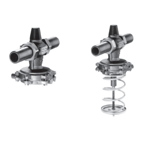
- Page 1 Differential Pressure Regulators with Flow Limitation Type 46-5 Type 46-6 Type 46-5 Type 46-6 Mounting and Operating Instructions EB 3130 EN Edition February 2010 Edition February 2010...
-
Page 2: Table Of Contents
Contents Contents Page Design and principle of operation ....4 Installation ......6 Mounting position . - Page 3 Safety instructions General safety instructions The regulators may only be installed, started up and serviced by fully trained and qualified personnel only, observing the accepted industry codes and practices. Make sure employees or third persons are not exposed to any danger. All safety instructions and warnings in these instructions, particularly those concerning installation, start-up and maintenance, must be observed.
-
Page 4: Design And Principle Of Operation
(6.1). In Type 46-5, the valve phragm. The resulting differential pressure is springs (5) integrated in the valve body de- converted into a positioning force at the dia- termine the set point. - Page 5 DN 15 to 32 · Δ set point range 0.2 to 1 bar Δp Turned into the plane of projection Δp Turned into the Type 46-5 · Screwed ends plane of projection Turned into the plane of projection Δp Table 1 · Tightening torques in Nm...
-
Page 6: Installation
An internal overload protection (excess pres- the main pipe (see Fig. 4) sure limiter) (6.4) in the actuator protects seat – Install a strainer (e.g. SAMSON Type 1 FN and plug from overload during exceptional Strainer) upstream of the valve, e.g. up- operating conditions that could lead to valve stream of the transfer station. -
Page 7: Strainer
Refer to installation schematics (Fig. 3) for Correct! line routing. Strainer Install a strainer (e.g. SAMSON Type 1FN) 4.4 · Connection at the side – correct upstream of the regulator to prevent sealing particles, weld spatter, pipe scale and other... -
Page 8: Operation
Operation Operation NOTICE When pressure-testing the pipelines with the Start-up regulator installed, make sure the test pres- sure does not exceed 1.5 times the nominal pressure. WARNING! The orifice to adjust the flow rate at the regu- First start up the regulator after mounting all lator must be completely open. -
Page 9: Adjusting The Flow Rate Limit
Operation NOTICE Do not adjust the set point to a scale value smaller than 1! Under certain conditions, the set point can- not be adjusted anymore as a result. In this case, the following action is recom- mended: – Relieve the process pressure from both sides of the regulator. -
Page 10: 3.4.1 Plant Pressure Drop Known
Operation 3.4.1 Plant pressure drop known 3.4.2 Plant pressure drop not known To adjust the flow rate limit when the pres- sure drop of the plant is known, use the ad- How to proceed justment diagrams (Fig. 7 to 9). Unscrew the cap (18). -
Page 11: Decommissioning
Operation The example shows that 6 turns (counter- Solution: (referring to A to E in Fig. 7) clockwise) are required, starting from the closed orifice (restriction). The calculation is based on the pressure drop Δp in the plant, therefore, you must know this Decommissioning value! Δp = 0.4 bar is specified in the example and... -
Page 12: 3.5.1 Pressure Conditions In The Plant And At The Regulator
Adjusted flow rate in m³/h Valve flow coefficient in m³/h Fig. 6 shows schematically the pressure conditions in the plant. Δp Δp set point Δp Δp plant restriction Type 46-5 Type 46-6 Fig. 6 · Pressure conditions at the regulator EB 3130 EN... - Page 13 Operation Differential pressure set point fixed for Type 46-5 Pressure loss in plant to be adjusted to 0.2, 0.3, 0.4 Δp in bar and 0.5 for Type 46-6 Limitation for Type 46-5 Turns of set point screw (scale division) V [m 3 /h] ˚...
- Page 14 Operation Differential pressure set point fixed for Type 46-5 to be adjusted to 0.2, 0.3, 0.4 Pressure loss in plant Δp in bar and 0.5 for Type 46-6 Turns of set point screw (scale division) V [m 3 /h] ˚...
- Page 15 Operation Differential pressure set point fixed for Type 46-5 Pressure loss in plant to be adjusted to 0.2, 0.3, 0.4 Δp in bar and 0.5 for Type 46-6 Turns of set point screw (scale division) V [m 3 /h] ˚...
-
Page 16: Maintenance - Replacing Parts
Check the control line for block- cannot be solved with the help of the infor- mation specified in the table, contact age. SAMSON. If the plug is damaged, replace the entire To replace the plug and diaphragm, proceed plug section. - Page 17 Maintenance – Replacing parts Type 46-6: Version with manual adjuster 1. Unscrew the control line (11). 2. Completely release the tension from the spring(s) (8) by turning the manual ad- juster (19) counterclockwise until a click- ing noise is heard. 3.
-
Page 18: Troubleshooting
Seat and plug untight Remove valve, clean seat and plug. If neces- pressure or sary, replace plug (section 4.1). flow rate Otherwise, return device to SAMSON for re- exceeds pair. adjusted set Operating diaphragm Replace diaphragm (section 4.2) or return de-... -
Page 19: Nameplate
Addresses of SAMSON subsidiaries, agencies and service centers are listed in the product catalogs and in the Internet at www.samson.de. To allow SAMSON to find the fault and to have an idea of the installation situation, specify the following details (refer to the nameplate):... -
Page 20: Dimensions And Weights
Dimensions and weights Dimensions and weights ØD Type 46-5 Connection nuts with welding ends ØD Type 46-6 Connection nuts with welding ends Connection nuts with threaded ends Connection nuts with flanges Ø116 Types 45-6 · Version with manual adjuster DN 15 to DN 32, set point ranges 0.1 to 1.0 bar Flanged body, DN 32/40/50 Fig. - Page 21 Table 4 · Dimensions in mm and weights in kg · Regulators including connection ends Nominal size DN With welding ends Length L1 Weight 46-5 approx. kg 46-6 10.0 10.5 Special version with threaded ends (male thread) Length L2 Male thread A G ½...
-
Page 22: Technical Data
Differential pressure set point ranges Type 46-6 · Set point 0.2 to 1 bar · 0.5 to 2 bar continuously adjustable Type 46-5 · Fixed set point 0.2 · 0.3 · 0.4 · 0.5 bar EB 3130 EN... - Page 23 EB 3130 EN...
- Page 24 SAMSON AG · MESS- UND REGELTECHNIK Weismüllerstraße 3 · 60314 Frankfurt am Main · Germany Phone: +49 69 4009-0 · Fax: +49 69 4009-1507 EB 3130 EN Internet: http://www.samson.de...
Need help?
Do you have a question about the 46-5 and is the answer not in the manual?
Questions and answers