Samson 42-34 Mounting And Operating Instructions
Differential pressure regulators with flow limitation
Hide thumbs
Also See for 42-34:
- Mounting and operating instructions (26 pages) ,
- Mounting and operating instructions (92 pages)

Related Manuals for Samson 42-34


Summary of Contents for Samson 42-34
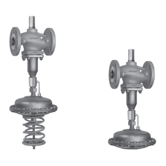
- Page 1 EB 3013 EN Translation of original instructions Type 42-38 Type 42-34 Type 42-34 and Type 42-8 Differential Pressure Regulators with Flow Limitation Self-operated Regulators Edition April 2021...
- Page 2 Note on these mounting and operating instructions These mounting and operating instructions assist you in mounting and operating the device safely. The instructions are binding for handling SAMSON devices. The images shown in these instructions are for illustration purposes only. The actual product may vary.
-
Page 3: Table Of Contents
Contents Safety instructions and measures ..............5 Notes on possible severe personal injury ............8 Notes on possible personal injury ..............9 Notes on possible property damage ..............10 Markings on the device ................12 2.1 Material identification number ..............13 Design and principle of operation ..............13 Versions ......................16 Technical data .....................16 3.2.1 Process medium and scope of application ............16... - Page 4 Contents Servicing.....................45 Replacing the operating diaphragm ..............46 Tightening torques and lubricants ..............48 Preparation for return shipment ..............49 Ordering spare parts and operating supplies ..........49 Malfunctions ....................49 Decommissioning and removal ..............51 10.1 Decommissioning ..................51 10.2 Disposal ......................52 Annex......................52 11.1 After-sales service ..................52 11.2 Certificates ....................52 EB 3013 EN...
-
Page 5: Safety Instructions And Measures
In case operators intend to use the devices in other applications or condi- tions than specified, contact SAMSON. SAMSON does not assume any liability for damage resulting from the failure to use the de- vice for its intended purpose or for damage caused by external forces or any other external factors. - Page 6 Î Observe safety measures for handling the device as well as fire prevention and explosion protection measures. Safety features The Type 42-34 and Type 42-38 Regulators do not have any special safety features. When relieved of pressure, the valve is opened and closes as the differential pressure rises. Responsibilities of the operator Operators are responsible for proper use and compliance with the safety regulations. Opera- tors are obliged to provide these mounting and operating instructions as well as the refer- enced documents to the operating personnel and to instruct them in proper operation.
- Page 7 Safety instructions and measures Responsibilities of operating personnel Operating personnel must read and understand these mounting and operating instructions as well as the referenced documents and observe the specified hazard statements, warnings and caution notes. Furthermore, operating personnel must be familiar with the applicable health, safety and accident prevention regulations and comply with them. Referenced standards, directives and regulations The devices comply with the requirements of the European Pressure Equipment Directive 2014/68/EU.
-
Page 8: Notes On Possible Severe Personal Injury
Safety instructions and measures 1.1 Notes on possible severe personal injury DANGER Risk of personal injury due to process medium escaping. The valve seal is opened when the actuator is removed from the valve. Residual pro- cess medium can escape and, depending on its properties, may lead to personal inju- ry, e.g. -
Page 9: Notes On Possible Personal Injury
Î Wear protective clothing and safety gloves. Damage to health relating to the REACH regulation. If a SAMSON device contains a substance which is listed as being a substance of very high concern on the candidate list of the REACH regulation, this circumstance is indi- cated on the SAMSON delivery note. -
Page 10: Notes On Possible Property Damage
Medium temperatures below 0 °C may cause ice to form on the regulator, depending on the air humidity. This may affect, in particular, the functioning of the actuator stem guide (Type 42-34). Î Prevent the formation of ice by taking appropriate precautions (e.g. enclosure, trace heater etc.). The plant operator is responsible for selecting and implementing appropriate precautions. See section 6.1.2. - Page 11 Safety instructions and measures NOTICE Risk of regulator damage due to incorrectly attached slings. Î Do not attach load-bearing slings to the actuator housing. Regulator damage due to condensed glycol. In principle, the materials are also resistant to high concentrations of glycol. Neverthe- less, glycol reacts when it comes into contact with metals and causes acids to form.
-
Page 12: Markings On The Device
Markings on the device Markings on the device Specifications on the actuator Flange version Effective area in cm² Type Configuration ID Index no. Pressure rating PN Valve size Set point range in bar Diaphragm material Specifications on the valve Flange version Type Model number index Configuration ID Order number/date... -
Page 13: Material Identification Number
The (Type 42-34) or a fixed set point (Type 42- pressure downstream of the restriction (1.4) 38). The flow rate can be limited by the re- is transmitted through the hollow plug stem striction integrated in the valve body. - Page 14 Design and principle of operation Type 42-34 · Type 42-38 · DN 15 to 250 · Balanced by a bellows Type 42-34 Type 42-38 DN 15 to 250 DN 15 to 100 Type 2423 Valve, balanced by a bellows 12.1 16, 20 Type 2428 Actuator Type 2424 Actuator Spring 12.1 Screw plug (balanced by a bel- lows, DN 125 and larger) Low-pressure control line (up to DN 100)
- Page 15 Design and principle of operation DN 65 to 100 · Balanced by a diaphragm DN 125 to 250 · Balanced by a diaphragm Type 2423 Valve, balanced by a diaphragm Type 2423 Valve, balanced by a diaphragm Optional 12.1 Type 2424 Actuator Type 2428 Actuator 12.2 Type 2424 Actuator Type 42-34 Type 42-38 Type 42-34 Valve body Seat 12.1 Diaphragm stem 1.1 Flow rate set point screw Plug 12.2 Diaphragm stem 1.2 Lock nut Plug stem 1.3 Cap...
-
Page 16: Versions
Differential pressure control and flow rate rect connection. limitation for district heating systems with in- − Type 42-34 · With adjustable differential direct connection, extended piping systems pressure limit and flow limitation · With and industrial applications. internal overload protection (excess pres- For flow rate from 0.05 to 520 m³/h sure limiter) in the actuator Differential pressure set points from 0.1 to... -
Page 17: Technical Data
Technical data Technical data Table 1: Technical data · Type 42-34 and Type 42-38 Type 2423 Valve balanced by a bellows Type 42-34 42-38 Valve size DN 15 to 250 DN 15 to 100 Pressure rating PN 16, 25 or 40 A = 160 cm² 1.2 bar 0.6 bar Pressure at which internal excess A = 320 cm² 0.6 bar 0.3 bar pressure limiter responds A = 640 cm²... - Page 18 Technical data Table 2: Data of Type 2423 Valve Type 2423 Valve balanced by a bellows Valve size DN Valve travel 10 mm 16 mm 22 mm coefficient value 0.65 0.55 0.45 0.35 Max. perm. differential pressure 25 bar 20 bar 16 bar 12 bar 10 bar ∆p Type 2423 Valve, balanced by a diaphragm Valve size DN coefficient value...
- Page 19 Technical data Dimensional drawing Type 42-34 Type 42-38 ØD ØD Fig. 4: Regulator with Type 2423 Valve balanced by a bellows ØD ØD Fig. 5: Regulator with Type 2423 Valve, balanced by a diaphragm EB 3013 EN...
- Page 20 Actuator ØD = 225 mm, A = 160 cm² ØD = 285 mm, A = 320 cm² 1.5 bar Weight 16.5 17.5 24.5 The weight applies to the version with the material specifications EN-GJL-250/PN 16. Add +10 % for spheroidal graphite iron EN-GJS-400-18-LT/PN 25, cast steel 1.0619/PN 40 and 1.4571. Optionally with 320 cm² actuator Minimum clearance required to remove the actuator: +100 mm Table 4: Dimensions in mm and weights · Type 42-34 · Type 2423 Valve balanced by a diaphragm Valve size DN 65 DN 80 DN 100 DN 125 DN 150 DN 200 DN 250 Length L...
- Page 21 Technical data Table 5: Dimensions in mm and weights · Type 42-38 · Type 2423 Valve balanced by a diaphragm Valve size DN 65 DN 80 DN 100 Length L Height H Height H2 Weight , approx. The weight applies to the version with the material specifications EN-GJL-250/PN 16. Add +10 % for all other materials. Minimum clearance required to remove the actuator: +100 mm Table 6: Flow rate set point ranges for water Type 2423 Valve balanced by a bellows ∆p ∆p...
-
Page 22: Measures For Preparation
2. Check the shipment for transportation WARNING damage. Report any damage to Risk of lifting equipment tipping over and SAMSON and the forwarding agent risk of damage to lifting accessories due to (refer to delivery note). exceeding the rated lifting capacity. -
Page 23: Transporting
Measures for preparation 5.2.1 Transporting − Make sure that the axis of the pipeline is always horizontal during lifting and the The regulator can be transported using lifting axis of the plug stem is always vertical. equipment (e.g. crane or forklift). Lifting the regulator Î Leave the regulator in its transport con- tainer or on the pallet to transport it. -
Page 24: Storage
Risk of regulator damage due to improper storage. − Observe the storage instructions. − Avoid long storage times. − Contact SAMSON in case of different stor- age conditions or longer storage times. Note We recommend regularly checking the de- vice and the prevailing storage conditions during long storage periods. -
Page 25: Preparation For Installation
− Store elastomers away from lubricants, chemicals, solutions and fuels. NOTICE Risk of impaired functioning of the regula- SAMSON's After-sales Service can provide tor and leakage at the joint due to installa- more detailed storage instructions on re- tion under tension. -
Page 26: Mounting Positions
Mounting and start-up 6.1 Mounting positions See Fig. 7 for permissible mounting posi- Contact SAMSON to obtain the tions. TV-SK 17041 documentation which contains more installation instructions. Standard mounting position Install valve without actuator in a horizontal pipeline with the connection for the actuator NOTICE facing downward. Make sure the medium Possible malfunction and damage due to... -
Page 27: Pipeline Routing
Î Observe the inlet and outlet lengths (see them. Table 7). Contact SAMSON if the valve conditions or states of the medium pro- cess deviate. Table 7: Inlet and outlet lengths Inlet and outlet lengths (control line) min. -
Page 28: Insulation
Mounting and start-up 6.1.2 Insulation 6.2 Control line and needle valve To insulate cold systems, we recommend first filling the plant and carefully rinsing it. The 6.2.1 Control line regulator must not be insulated until the set point is adjusted. See section 7. Depending on the regulator version, a con- Î Start up the plant and adjust the set trol line (standard: 8x1 mm steel or stainless point. -
Page 29: Needle Valve
Mounting and start-up 6.2.2 Needle valve If the regulator tends to hunt, we recommend installing a SAMSON needle valve at the control line installed on site (connection of the actuator). Needle valves and compression-type screw fittings can be supplied as required. These –... -
Page 30: Additional Fittings
For example, maintenance, and when the plant is not used the SAMSON Type 2 NI Strainer is suitable for longer periods of time. (u T 1015). Pressure gauges − Do not use the strainer to permanently... -
Page 31: Installing The Regulator
Mounting and start-up 6.4 Installing the regulator 6.5 Start-up 1. Close the shut-off valves in the pipeline DANGER while the valve is being installed. Risk of personal injury due to process 2. Remove the protective caps from the medium escaping. flanges before installing the valve. - Page 32 Mounting and start-up Î If needle valves are installed in the con- Rinsing the plant trol lines, open them before start-up. 1. After filling the plant, first completely open the consumer If this is not possible, NOTICE open the bypass. Risk of valve damage due to a sudden 2.
-
Page 33: Operation
Operation Operation 7.1.1 Adjusting the differential pressure 7.1 Adjusting the set points Type 42-34 · Adjust the desired differential pressure at the set point adjuster (17, width The following generally applies: First adjust across flats 27) with the plant almost shut the differential pressure and the flow limita- and with fully open restriction (1.4). First af- tion afterwards. terwards adjust the limit value for the flow rate. -
Page 34: Adjusting The Flow Limitation
Operation 7.1.2 Adjusting the flow justment diagrams for water (Fig. 16 to Fig. 11). limitation Note NOTICE Using the set point screw (1.1) Set point adjustment is always based on a − Turn clockwise : closed restriction (1.4). The restriction closes. The flow rate drops. − Turn counterclockwise : How to proceed: The restriction opens. -
Page 35: Based On An Unknown Plant Pressure Drop
4. Secure restriction setting using the lock If the maximum flow rate is not reached, nut (1.2) at the set point screw (1.1). the differential pressure set point (in Screw cap (1.3) back on. Type 42-34) must be increased. 5. Lead-seal the set point screw at the cap (1.3). NOTICE To determine the flow limitation to be adjusted and for Type 42-38 additionally... -
Page 36: Pressure Conditions In The Plant And At The Regulator
Operation 5. After reaching the required flow rate, secure the restriction setting using the lock nut (1.2). Screw cap (1.3) back on. 6. Lead-seal the set point screw at the cap (1.3). 7. Lead-seal the actuator at the spindle. 7.2 Pressure conditions in the plant and at the regulator On selecting the differential pressure set point or set point range, note that the differential pressure set point ( ) results from the known pressure drop across the fully open plant Δp... -
Page 37: Sample Application
∆p ∆p when the pressure loss across the plant is Anlage Wirk known. Known: − A Type 42-34, DN 25, set point range Type 42-34 from 0.25 to 3.5 m³/h is to be used to limit the flow rate in the plant to Type 42-38 3.0 m³/h. Fig. 10: Pressure conditions in the plant − The pressure loss across the plant (... - Page 38 Operation To be determined: What is the limit value of the differential pressure set point and how many turns of the set point screw are necessary? Solution: Sequence: points A to E in diagram (Fig. 11). The calculation is based on the pressure drop Δp in the plant, therefore, this value must be known. Δp = 0.4 bar is specified in the example and corresponds with point A in the diagram. The differential pressure at the restriction ( Δp ) assumed to be 0.2 bar in the example, restriction...
- Page 39 Operation Differential pressure set point (fixed in Type 42-38, adjustable in Type 42-34) Δp (bar) Pressure loss in the plant Turns of the set point screw (flow set point adjustment) ˚ DN 15 DN 20 DN 25 Differential pressure at restriction Δp (bar) Fig. 11: Adjustment diagram DN 15 to 25 EB 3013 EN...
- Page 40 Operation Differential pressure set point (fixed in Type 42-38, adjustable in Type 42-34) Δp (bar) Pressure loss in the plant Turns of the set point screw (flow set point adjustment) ˚ 12,0 DN 32 15,0 18,0 DN 40 21,0 24,0 27,0 DN 50 Differential pressure at restriction Δp (bar) Fig. 12: Adjustment diagram DN 32 to 50...
- Page 41 Operation Differential pressure set point (fixed in Type 42-38, adjustable in Type 42-34) Δp (bar) Pressure loss in the plant Turns of the set point screw (flow set point adjustment) ˚ 10 9 DN 65 DN 80 DN 100 Differential pressure at restriction Δp (bar) Fig. 13: Adjustment diagram DN 65, 80 and 100 EB 3013 EN...
- Page 42 Operation Differential pressure set point (Type 42-34) Δp (bar) Pressure loss in the plant Turns of the set point screw (flow set point adjustment) ˚ DN 125 DN 150 Differential pressure at restriction Δp (bar) Fig. 14: Adjustment diagram DN 125 to 150 EB 3013 EN...
- Page 43 Operation Differential pressure set point (Type 42-34) Δp (bar) Pressure loss in the plant Turns of the set point screw (flow set point adjustment) ° V max m 3 /h DN 250 DN 200 Differential pressure at restriction Δp (bar) Fig. 15: Adjustment diagram, DN 200 and 250 ·...
- Page 44 Operation Differential pressure set point (Type 42-34) Δp (bar) Pressure loss in the plant Turns of the set point screw (flow set point adjustment) ° V max m 3 /h DN 200 DN 250 Differential pressure at restriction Δp (bar) Fig. 16: Adjustment diagram, DN 200 and 250 ·...
-
Page 45: Servicing
− If possible, drain the process medium from all the plant sections affected and the regu- lator. SAMSON's After-sales Service can support − Wear protective clothing, safety gloves and you in drawing up an inspection and test eye protection. -
Page 46: Replacing The Operating Diaphragm
Disassembling Type 2428 Actuator 1. Put the regulator out of operation (see Note section 10.1). The regulator was checked by SAMSON be- 2. Unscrew the control lines from the dia- fore it left the factory. phragm actuator and undo the coupling − The product warranty becomes void if nuts (11). - Page 47 Servicing 10. Pull the force limiter (20) together with Note the diaphragm stem (12.1) out of the ac- The stem surface is roller-burnished. Do not tuator housing. reface the stem. 11. Check the screw fittings for dirt and After replacing the diaphragm stem, the nip- clean them, if necessary. ple (guide bushing) in the actuator case must be replaced as well.
-
Page 48: Tightening Torques And Lubricants
Servicing Assembly of Type 2424 Actuator 6. Place on the diaphragm case ('+' cham- ber) and tighten the screws (15) evenly. 1. Apply lubricant to the diaphragm stems Observe tightening torque specified in (12.1 and 12.2). See section 8.2. section 8.2. 2. Insert the operating diaphragm assem- 7. Place the set point springs (16) and set bly, consisting of the diaphragm plate point adjuster (17) on the diaphragm (19), operating diaphragm (13) and dia- stem (12.2) and tighten by hand. -
Page 49: Preparation For Return Shipment
8.4 Ordering spare parts and scribed. operating supplies Contact your nearest SAMSON subsidiary or the SAMSON's After-sales Service for in- formation on spare parts and tools. EB 3013 EN... - Page 50 Remove valve from the pipeline and clean seat and plug. Replace the plug, if Leak between seat and plug possible. If this is not possible, return regulator to SAMSON for repair. Flow rate or differential Replace operating diaphragm or return pressure exceeds adjusted set Defective operating diaphragm regulator to SAMSON for repair.
-
Page 51: Decommissioning And Removal
Decommissioning and removal 10. Decommissioning and WARNING removal Risk of burn injuries due to hot or cold com- ponents and pipeline. Regulator components and the pipeline may DANGER become very hot or cold. Risk of burn inju- Risk of bursting in pressure equipment. ries. -
Page 52: Disposal
E-mail address You can reach our after-sales service at aftersalesservice@samsongroup.com. Addresses of SAMSON AG and its subsid- iaries The addresses of SAMSON, its subsidiaries, representatives and service facilities worldwide can be found on our website (u www.samsongroup.com) or in all... - Page 53 Annex Modul H/Module H, Nr./No. / N° CE-PED-H-SAM 001-13-DEU-rev-A SAMSON erklärt in alleiniger Verantwortung für folgende Produkte:/For the following products, SAMSON hereby declares under its sole responsibility: Ventile für Druck-, Differenzdruck-, Temperatur- und Volumenstromregler/Valves for pressure, temperature, flowregulators and differential pressure regulators Typ 2336, 2373, 2375, 44-1B, 44-2, 44-3, 44-4, 44-6B, 44-9, 45-1, 45-2, 45-3, 45-4, 45-6, (Erz.-Nr.
- Page 54 Annex Modul H/Module H, Nr./No. / N° CE-0062-PED-H-SAM 001-16-DEU-rev-A SAMSON erklärt in alleiniger Verantwortung für folgende Produkte:/For the following products, SAMSON hereby declares under its sole responsibility: Ventile für Druck- Differenzdruck-, Volumenstrom- und Temperaturregler/Valves for pressure, differential pressure, volume flow and temperature regulators 2333 (Erz.-Nr./Model No.
- Page 55 Annex EB 3013 EN...
- Page 56 EB 3013 EN SAMSON AKTIENGESELLSCHAFT Weismüllerstraße 3 · 60314 Frankfurt am Main, Germany Phone: +49 69 4009-0 · Fax: +49 69 4009-1507 samson@samsongroup.com · www.samsongroup.com...
Need help?
Do you have a question about the 42-34 and is the answer not in the manual?
Questions and answers