Samson 46-7 Mounting And Operating Instruction
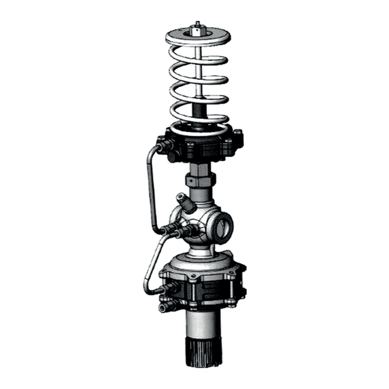
Flow and differential pressure regulator with additional pressure control actuator
Hide thumbs
Also See for 46-7:
- Mounting and operating instructions (44 pages) ,
- Mounting and operating instructions (48 pages)

Related Manuals for Samson 46-7


Summary of Contents for Samson 46-7
- Page 1 EB 3131-1 EN Translation of original instructions Type 46-7 Flow and Differential Pressure Regulator with additional pressure control actuator Self-operated Regulators Edition December 2020...
- Page 2 Î For the safe and proper use of these instructions, read them carefully and keep them for later reference. Î If you have any questions about these instructions, contact SAMSON‘s After-sales Service (aftersalesservice@samsongroup.com). The mounting and operating instructions for the devices are included in the scope of delivery.
-
Page 3: Table Of Contents
Contents Safety instructions and measures ..............4 Notes on possible severe personal injury ............6 Notes on possible personal injury ..............7 Notes on possible property damage ..............8 Markings on the device .................9 Design and principle of operation ..............10 Technical data .....................13 Measures for preparation ................17 Unpacking ....................17 Transporting and lifting ................17 Storage .......................17... -
Page 4: Safety Instructions And Measures
In case operators intend to use the devices in other applications or conditions than specified, contact SAMSON. SAMSON does not assume any liability for damage resulting from the failure to use the de- vice for its intended purpose or for damage caused by external forces or any other external factors. - Page 5 Î Check with the plant operator for details on further protective equipment. Revisions and other modifications Revisions, conversions or other modifications of the product are not authorized by SAMSON. They are performed at the user's own risk and may lead to safety hazards, for example. Fur- thermore, the product may no longer meet the requirements for its intended use.
-
Page 6: Notes On Possible Severe Personal Injury
Safety instructions and measures Referenced standards, directives and regulations The regulators comply with the requirements of the European Pressure Equipment Directive 2014/68/EU. Devices with a CE marking have a declaration of conformity, which includes information about the applied conformity assessment procedure. This declaration of confor- mity is included in the annex of these instructions (see section 10.2). -
Page 7: Notes On Possible Personal Injury
Î Wear protective clothing and safety gloves. Damage to health relating to the REACH regulation. If a SAMSON device contains a substance which is listed as being a substance of very high concern on the candidate list of the REACH regulation, this circumstance is indicat- ed on the SAMSON delivery note. Î Information on safe use of the part affected u www.samsongroup.com/en/ about-samson/material-compliance/reach-regulation/. -
Page 8: Notes On Possible Property Damage
Safety instructions and measures 1.3 Notes on possible property damage NOTICE Risk of valve damage due to contamination (e.g. solid particles) in the pipeline. The plant operator is responsible for cleaning the pipelines in the plant. Î Flush the pipelines before start-up. Î... -
Page 9: Markings On The Device
5 Pressure rating PN or Class Differential pressure set point range in bar or 7 Type designation 8 Flow rate set point range in m³/h or gal/min Nameplate of Type 46-7 9 Maximum permissible temperature in °C or °F Max. permissible differential pressure ∆p in bar or psi 1 Set point range (pressure) in bar or psi... -
Page 10: Design And Principle Of Operation
Design and principle of operation 3 Design and principle of oper- To control the flow rate, the low pressure downstream of the restriction is transmitted ation through a hole in the plug to the top dia- ˙ The combined regulators mainly consist of phragm chamber A. The high pressure of V the valve (1), closing actuator (6) with two is transmitted through the attached control operating diaphragms (6.1, 6.3) and an ad-... - Page 11 Design and principle of operation 15.1 15.4 15.2 15.3 15.2 • Δp Fig. 1: Flow and differential pressure regulator with additional pressure control actuator · DN 15 and 25 EB 3131-1 EN...
- Page 12 Design and principle of operation Set point spring (differential pressure) Restriction Knurled nut (flow rate, SW 5) Nipple with retaining screw and lead-seal hole Set point adjuster (differential pressure) Fig. 2: Flow and differential pressure regulator with additional pressure control actuator · DN 40 EB 3131-1 EN...
-
Page 13: Technical Data
Design and principle of operation 3.1 Technical data Dimensions and weights The lengths and heights in the dimensional Process medium and scope of application drawings are shown on pages 15 and Flow rate and differential pressure control with pressure control in district heating sup- Dimensions in mm · Weights in kg ply networks and industrial plants · Valves DN 15, 25 and 40 · Pressure rating PN 16 Note... - Page 14 Design and principle of operation Table 1: Technical data Valve size DN 15 DN 25 DN 40 coefficient 0.55 0.55 value PN 16/25 PN 16/25 PN 25 Pressure rating 10 bar 10 bar – PN 16 Max. permissible differential pressure ∆p across the valve 20 bar 20 bar 16 bar PN 25 130 °C 130 °C – PN 16 Max.
- Page 15 Design and principle of operation Dimensional drawings ØD2 ØD2 ØD1 DN 15 and 25 ØD1 DN 40 EB 3131-1 EN...
- Page 16 Design and principle of operation Table 3: Regulator with connecting parts Valve size DN 15 DN 25 DN 40 With welding ends Weight, approx. With threaded ends Male thread A G ½ G 1 G 1½ Weight, approx. With flanges or with flanged body (DN 40) 1) 2) 16.0 Weight, approx.
-
Page 17: Measures For Preparation
− Observe the storage instructions. note. − Avoid long storage times. 2. Check the shipment for transportation − Contact SAMSON in case of different stor- damage. Report any damage to age conditions or longer storage times. SAMSON and the forwarding agent (refer to delivery note). -
Page 18: Mounting And Start-Up
− Make sure that the regulator remains freely accessible after the plant has been completed. SAMSON's After-sales Service can provide − Install a strainer upstream of the regula- more detailed storage instructions on re- tor (see section 5.2). quest. - Page 19 The inlet and outlet lengths vary depending on several variables and process conditions Î Observe the inlet and outlet lengths (see and are intended as recommendations. Con- Fig. 4). Contact SAMSON if the regula- tact SAMSON if the lengths are significantly tor conditions or state of the medium shorter than the recommended lengths.
-
Page 20: Additional Fittings
Preferably connect the carried along by the medium. For example, control line to the side of the main pipe. the SAMSON Type 1 NI Strainer is suitable Î Do not change the pipe diameter of the (u T 1010). main pipeline with an eccentric reducer. - Page 21 Mounting and start-up Correct Connection at the top – incorrect position Connection at the side – optimal Connection at the bottom – incorrect position Fig. 5: Control line connection Table 4: Accessories NOTICE Accessories Item no. Risk of valve damage due to a sudden Blanking plug 8323-0030 pressure increase and resulting high flow...
-
Page 22: Operation
Operation 6 Operation 15.1 6.1 Adjusting the set points 6.1.1 Flow control Î Adjust the maximum differential pressure 15.4 at the regulator (see section 6.1.2). Î Completely open the control and shut-off valves or a bypass valve in the plant. DN 15 and 25 1. To place the restriction (9) in the end po- sition, relieve the tension from the set point spring (15.4) at the pressure con- trol actuator (15) by turning the set point... - Page 23 Operation turning the set point adjuster (15.1) clockwise () as far as it will go. 3. Refer to Fig. 8 to find out how many 15.1 turns are required to set the flow rate. 4. Turn the knurled nut (9.2) by the required number of turns. Turn it counterclockwise () to open the restriction. The flow rate rises. 15.4 5. Tighten the retaining screw (9.3) with a suitable tool (Allen key, SW 5) to fix the adjusted flow rate. Pull the wire through the lead-seal hole and lead-seal it.
- Page 24 Operation Table 5: Flow rate set point range for water in m³/h Valve size DN coefficient Set point range with ∆p restriction 0.6 to 2.5 m³/h 0.8 to 3.5 m³/h 3 to 6.6 m³/h 0.2 bar DN 40 DN 25 DN 15 Flow rate in m³/h Fig. 8: Set point adjustment for flow rate: differential pressure across the restriction Δp = 0.2 bar restriction...
-
Page 25: Differential Pressure Control
Operation 6.1.2 Differential pressure Turn clockwise () to load the set point spring (8). The Δp set point increases. control Turn counterclockwise () to relieve the 1. Close the shut-off valves or the bypass to tension from the set point spring (8). The reduce the maximum flow rate to ap- Δp set point is reduced. prox. 5 to 10 %. The set point spring is installed in the bottom If you are using a motorized valve, close section of the housing in DN 15 and 25. The... - Page 26 Operation adjuster according to the value on the scale NOTICE (see Fig. 10). Risk of regulator malfunction due to incor- rect setting. Note A scale value below 1 may lead to incorrect The maximum value on the scale of the set control. point adjuster is 8.
-
Page 27: Pressure Control
Operation 6.1.3 Pressure control Note The adjusted pressure changes by 0.03 bar Adjusting the pressure set point at the set after each turn of the set point adjuster with point adjuster a set point range from 1.0 to 2.2 bar. Î Adjust the pressure set point while watching the pressure gauge on the Adjusting the pressure set point by chang- downstream pressure side. -
Page 28: Pressure Measurement At The Regulator
Operation The adjustment diagram in Fig. 12 applies to the pressure control when the valve is closed (deviation ±0. bar). The associated spring travel is assigned to a certain set point in the range from 1.0 to 2.5 bar. 6.2 Pressure measurement at the regulator Î Screw a suitable pressure gauge in place of the blanking plug (G ... -
Page 29: Servicing
Nevertheless, it is subject to natural Defective devices can be returned to wear, particularly at the seat, plug and oper- SAMSON for repair. Proceed as follows to ating diaphragm. Depending on the operat- return devices to SAMSON: ing conditions, check the regulator at regular 1. -
Page 30: Malfunctions
WARNING SAMSON's After-sales Service can help Risk of burn injuries due to hot or cold com- during troubleshooting. Further information ponents and pipelines. is available in section 10.1. - Page 31 SAMSON for repair. Recalculate K and contact Control loop hunts. Valve too large for control task SAMSON for further action. Note Contact SAMSON's After-sales Service for malfunctions not listed in the table and when the malfunction cannot be remedied as described. EB 3131-1 EN...
-
Page 32: Decommissioning And Removal
Decommissioning and removal 9 Decommissioning and 9.1 Decommissioning removal To decommission the regulator for service and repair work or disassembly, proceed as follows: DANGER Risk of bursting in pressure equipment. 1. Close the shut-off valve on the upstream Control valves and pipelines are pressure side of the valve. -
Page 33: Annex
E-mail address You can reach our after-sales service at aftersalesservice@samsongroup.com. Addresses of SAMSON AG and its subsid- iaries The addresses of SAMSON, its subsidiaries, representatives and service facilities worldwide can be found on our website (u www.samsongroup.com) or in all... - Page 34 2333 (Erz.-Nr./Model No. 2333), 2334 (2334), 2335 (2335), 2336, 2373, 2375, 44-0B, 44-1B, 44-2, 44-3, 44-6B, 44-7, 44-8, 45-1, 45-2, 45-3, 45-4, 45-5, 45-6, 2468, 2478 (2720), 45-9, 46-5, 46-6, 46-7, 46-9, 47-1, 47-4, 47-5, 47-9, 2487, 2488, 2489, 2491, 2494, 2495 (2730), 2405, 2406, 2421 (2811), 2392, 2412 (2812), 2114 (2814), 2417 (2817), 2422 (2814), 2423 (2823) die Konformität mit nachfolgender Anforderung/the conformity with the following requirement.
- Page 35 EB 3131-1 EN...
- Page 36 EB 3131-1 EN SAMSON AKTIENGESELLSCHAFT Weismüllerstraße 3 · 60314 Frankfurt am Main, Germany Phone: +49 69 4009-0 · Fax: +49 69 4009-1507 samson@samson.de · www.samson.de...
Need help?
Do you have a question about the 46-7 and is the answer not in the manual?
Questions and answers