Table of Contents
Advertisement
Quick Links
Advertisement
Table of Contents

Subscribe to Our Youtube Channel
Related Manuals for Samson 42-20


Summary of Contents for Samson 42-20
- Page 1 EB 3007 EN Translation of original instructions Type 42-25 Differential Pressure Regulator Type 42-20 Differential Pressure Regulator Type 42-20 and Type 42-25 Differential Pressure Regulators Self-operated Regulators · Opening Actuator Edition October 2022...
- Page 2 Note on these mounting and operating instructions These mounting and operating instructions assist you in mounting and operating the device safely. The instructions are binding for handling SAMSON devices. The images shown in these instructions are for illustration purposes only. The actual product may vary.
-
Page 3: Table Of Contents
Contents Safety instructions and measures ..............1-1 Notes on possible severe personal injury ............1-4 Notes on possible personal injury ..............1-5 Notes on possible property damage .............1-7 Markings on the device ................2-1 Nameplates ....................2-1 Location of the nameplates ................2-2 2.3 Material identification number ..............2-2 2.3.1 Type 2422 Valve ..................2-2 2.3.2... - Page 4 Decommissioning ..................10-1 Removal ....................11-1 11.1 Removing the regulator from the pipeline ............11-1 11.2 Removing the actuator from the valve ............11-1 Repairs ....................12-1 12.1 Returning devices to SAMSON ..............12-1 Disposal ....................13-1 Certificates ....................14-1 Annex......................15-1 15.1 Tightening torques ..................15-1 15.2 Lubricant ....................15-1 15.3...
-
Page 5: Safety Instructions And Measures
In case operators intend to use the regulators in other applications or conditions than specified, contact SAMSON. SAMSON does not assume any liability for damage resulting from the failure to use the de- vice for its intended purpose or for damage caused by external forces or any other external factors. - Page 6 Safety footwear, ESD (electrostatic discharge) footwear, if necessary Î Check with the plant operator for details on further protective equipment. Revisions and other modifications Revisions, conversions or other modifications of the product are not authorized by SAMSON. They are performed at the user's own risk and may lead to safety hazards, for example. Fur- thermore, the product may no longer meet the requirements for its intended use. Warning against residual hazards...
- Page 7 Start-up and shutdown procedures fall within the scope of the operator's duties and, as such, are not part of these mounting and operating instructions. SAMSON is unable to make any statements about these procedures since the operative details (e.g. differential pressures and temperatures) vary in each individual case and are only known to the operator.
-
Page 8: Notes On Possible Severe Personal Injury
Safety instructions and measures Referenced documentation The following documents apply in addition to these mounting and operating instructions: – Mounting and operating instructions for e.g. Type 2 N/NI Strainer u EB 1015 – Data sheets for e.g. Accessories · Differential pressure and flow regulators u T 3095 e.g. -
Page 9: Notes On Possible Personal Injury
Safety instructions and measures 1.2 Notes on possible personal injury WARNING Risk of personal injury through incorrect operation, use or installation as a result of information on the regulator being illegible. Over time, markings, labels and nameplates on the regulator may become covered with dirt or become illegible in some other way. As a result, hazards may go unno- ticed and the necessary instructions not followed. - Page 10 Î Wear protective clothing and safety gloves. Damage to health relating to the REACH regulation. If a SAMSON device contains a substance which is listed as being a substance of very high concern on the candidate list of the REACH regulation, this circumstance is indi- cated on the SAMSON delivery note.
-
Page 11: Notes On Possible Property Damage
The lubricants to be used depend on the regulator material. Unsuitable lubricants may corrode and damage surfaces. Î Only use lubricants approved by SAMSON. When in doubt, consult SAMSON. Risk of leakage and regulator damage due to excessively high or low tightening torques. - Page 12 Î Prevent the formation of ice by taking appropriate precautions (e.g. enclosure, trace heater etc.). The plant operator is responsible for selecting and implementing appropriate precautions. See the 'Installation' section. Note SAMSON's After-sales Service can support you concerning lubricant, tightening torques and tools approved by SAMSON. EB 3007 EN...
-
Page 13: Markings On The Device
Markings on the device 2 Markings on the device Several nameplates are affixed to the device. The nameplates are used to identify the sepa- rate regulator components (see section 2.1). 2.1 Nameplates Nameplates of Type 2422 Valve DIN version ANSI version ANSI version · DIN version 4 Order number or date 8 Pressure rating 1 Valve type 9 Perm. differential pressure 2 Model number with index 6 Unassigned 10 Perm. -
Page 14: Location Of The Nameplates
Markings on the device 2.2 Location of the nameplates 2.3 Material identification number 2.3.1 Type 2422 Valve See the nameplate (11 for DIN/ANSI ver- Location of the sion, body material) for the material used. nameplate on the For more details on the nameplate, see sec- regulator tion 2.1. -
Page 15: Design And Principle Of Operation
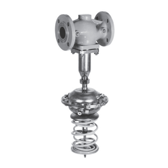
This force moves the plug according to lines to a defined set point. the force of the set point springs (16). Type 42-20 · The set point is fixed. The set point springs are mounted inside the Type 42-25 · The set point can be adjusted actuator for a fixed set point (Type 42-20). as required within the set point range. - Page 16 Design and principle of operation Type 2422 Valve, balanced by a bellows (DN 15 to 250) Type 42-20 with Type 2420 Actuator Type 42-25 with Type 2425 Actuator with two diaphragms Type 42-25 with Type 2425 Actuator Fig. 3-1: Functional diagram for regulators, DN 15 to 250 with balancing bellows EB 3007 EN...
- Page 17 Design and principle of operation Type 2422 Valve, balanced by a diaphragm (DN 65 to 250) Type 42-20 with Type 2420 Actuator Type 42-25 with Type 2425 Actuator with two diaphragms Type 42-25 with Type 2425 Actuator Fig. 3-2: Functional diagram for regulators, DN 65 to 250 with balancing diaphragm Legend for Fig. 3-1 and Fig. 3-2 Valve body...
-
Page 18: Additional Fittings
6 Shut-off valve regulator 2 Strainer 7 Needle valve (optional) Pressure gauge (return flow 3 Pressure gauge (flow pipe) Compensation chamber pipe) (optional) Fig. 3-3: Installation example: Type 42-20 and Type 42-25. The control lines to be installed on site are represented by a dashed line. EB 3007 EN... -
Page 19: Technical Data
Suitable for liquids and vapors, max. temperature 350 °C/660 °F 1) Note – Suitable for gases, The Type 42-20 and Type 42-25 Regulators max. temperature 80 °C/175 °F are not safety valves. If necessary, a suitable overpressure protection must be installed on – Set points from 0.05 to 10 bar site in the plant section. - Page 20 (u T 3007). Leakage class Noise emissions The metal-seated regulator has the leakage SAMSON is unable to make general state- class I according to IEC 60534-4. ments about noise emissions. The noise emis- The soft-seated regulator has the leakage sions depend on the regulator version, plant class IV according to IEC 60534-4.
- Page 21 Design and principle of operation Table 3-2: Materials · Material numbers according to DIN EN Type 2422 Valve · Balanced by a bellows Valve size DN 15 to 250 Pressure rating PN 16 PN 16, 25 PN 16, 25, 40 Cast iron Sph. graphite iron Cast steel Cast stainless steel Forged stainless Valve body EN-GJL-250...
- Page 22 Design and principle of operation Table 3-3: K coefficients, x values and max. permissible differential pressures ∆p Type 2422 Valve · Balanced by a bellows Valve size DN 200 250 Valve travel 10 mm 16 mm 22 mm coefficient 420 500 Max. permissible differential 25 bar 20 bar 16 bar...
- Page 23 Design and principle of operation Table 3-4: Dimensions and weights for Type 42-20 and Type 42-25 · Balanced by a bellows Dimensions in mm · Weights in kg (without process medium) Valve size Length L 130 150 Up to 220 °C Height H1 Up to 350 °C Forged steel –...
- Page 24 Design and principle of operation Table 3-4: Dimensions and weights for Type 42-20 and Type 42-25 · Balanced by a bellows Dimensions in mm · Weights in kg (without process medium) Valve size Height H 940 1070 1210 5) 6) 1 to Actuator ØD = 225 mm, A = 160 cm² 2.5 bar...
- Page 25 Design and principle of operation Table 3-5: Dimensions and weights for Type 42-20 and Type 42-25 · Balanced by a diaphragm Dimensions in mm · Weights in kg (without process medium) Valve size DN Height H2 Height H6 Max. + 220 mm Height H7 + 55 mm Type 42-25 Differential Pressure Regulator Set points Type 2420 Actuator...
- Page 26 Design and principle of operation Table 3-6: Weights of Type 2420 and Type 2425 Actuators · Weights in kg (without process medium) Actuator area in cm² 160 · 80 · 40 Weight in kg Weight of Type 2425 Actuator with two diaphragms on request Dimensional drawings Type 42-25 Type 2422 Valve balanced by a bellows with Type 2422 Valve balanced by a diaphragm with Type 2425 Actuator Type 2425 Actuator ØD...
- Page 27 Design and principle of operation Dimensional drawings Type 42-20 Type 2422 Valve balanced by a bellows with Type 2422 Valve balanced by a diaphragm with Type 2420 Actuator Type 2420 Actuator ØD Fig. 3-4: Dimensions, Type 2422 Valve with Type 2420 and Type 2425 Actuators EB 3007 EN 3-13...
- Page 28 Design and principle of operation Dimensional drawings Extension piece Actuator with two diaphragms Metal cover Ø D Fig. 3-5: Dimensions of extension piece, actuator with two diaphragms and metal cover 3-14 EB 3007 EN...
-
Page 29: Shipment And On-Site Transport
2. Check the shipment for transportation They prevent foreign particles from enter- damage. Report any damage to ing the valve. SAMSON and the forwarding agent (re- Î Dispose and recycle the packaging in ac- fer to delivery note). cordance with the local regulations. -
Page 30: Transporting And Lifting The Regulator
Shipment and on-site transport 4.3 Transporting and lifting the WARNING regulator Risk of personal injury due to the regulator tipping. Î Observe the regulator's center of gravity. DANGER Î Secure the regulator against tipping over Danger due to suspended loads falling. or turning. -
Page 31: Lifting The Regulator
Shipment and on-site transport Transport instructions Lifting Î Protect the regulator against external in- 1. Attach one sling to the flange of the fluences (e.g. impact). body and to the rigging equipment (e.g. hook) of the crane or forklift (see Î Do not damage the corrosion protection Fig. 4-1). (paint, surface coatings). Repair any damage immediately. -
Page 32: Storing The Regulator
Î Observe the storage instructions. Î Store elastomers away from lubricants, Î Avoid long storage times. chemicals, solutions and fuels. Î Contact SAMSON in case of different − We recommend a storage temperature of storage conditions or longer storage 15 °C for elastomers. -
Page 33: Installation
Con- tact SAMSON if the lengths are significantly Î Contact SAMSON if the mounting posi- shorter than the recommended lengths. tion is not as specified above. To ensure that the regulator functions proper- NOTICE ly, proceed as follows: Damage due to freezing. - Page 34 The plant engineering company is responsi- installing a needle valve in the control line in ble for selecting and implementing a suitable addition to the standard SAMSON screw support or suspension of the installed regula- joint with restriction. The standard SAMSON tor and the pipeline.
- Page 35 Installation Compensation chamber Correct A compensation chamber (8) is required for liquids above 150 °C as well as for steam (see Fig. 5-4). Install the compensation chamber at the highest point of the pipeline. Connection at the side – optimal The mounting position of the compensation chamber is indicated by an adhesive label on the chamber itself as well as by an arrow and the word "top"...
-
Page 36: Preparation For Installation
4 Differential pressure regulator 7 Needle valve (optional) 2 Strainer Pressure gauge (return flow Compensation chamber pipe) (optional) 3 Pressure gauge (flow pipe) 6 Shut-off valve Fig. 5-4: Installation example: Type 42-20 and Type 42-25. The control lines to be installed on site are represented by a dashed line. EB 3007 EN... -
Page 37: Installation
WARNING The components (valve, actuator and, if ap- Risk of injury due to incorrect lifting without plicable, accessories) of the SAMSON regu- the use of lifting equipment. lator are delivered separately. Upon deliv- Lifting the regulator without the use of lifting... -
Page 38: Installing The Regulator
Risk of regulator damage due to the use of 3. Lift the valve using suitable lifting equip- unsuitable tools. ment to the site of installation. Observe Î Only use tools approved by SAMSON the flow direction through the valve. The (see 'Tools' in Annex). arrow on the valve indicates the direction of flow. -
Page 39: Testing The Regulator
The regulator components are delivered by SAMSON ready for use. To test the regulator functioning before start-up or putting back the regulator into operation, perform the fol- lowing tests: EB 3007 EN... -
Page 40: Leak Test
The plant operator is responsible for per- stalled shut-off valve or inserting a blank- forming the pressure test. SAMSON's Af- ing plug. ter-sales Service can support you to plan and perform a pressure test for your plant. -
Page 41: Filling The Plant
Installation Pressure test without mounted diaphragm actuator WARNING Risk of personal injury due to pressurized components and process medium being dis- charged. Incorrect opening of pressure equipment or mounting parts may lead to the process me- dium escaping to the atmosphere. Î... -
Page 42: Cleaning The Pipeline
Installation 5.4.4 Cleaning the pipeline 5.5 Insulation We recommend additionally flushing the To insulate cold systems, we recommend first pipeline with installed regulator over a time filling the plant and carefully rinsing it. The period of several minutes before start-up. regulator must not yet be insulated at this stage. Î All required control lines are connected and not shut off. 1. -
Page 43: Start-Up
Start-up 6 Start-up Î Wear hearing protection when working near the valve. Follow the instructions The work described in this section is only to given by the plant operator. be performed by personnel appropriately qualified to carry out such tasks. Before start-up or putting the device back in- to service, make sure the following condi- WARNING tions are met:... -
Page 44: Starting Up The Plant
Start-up Before starting up the plant, make sure the regulator to avoid damaging the balanc- following conditions are met: ing bellows or diaphragm. – The control lines are open (needle valve) Regulation of liquids and correctly connected. Î For liquid medium temperatures above 150 °C, first fill the compensation cham- 6.2 Starting up the plant ber with the process medium. -
Page 45: Operation
Incorrect opening of pressure equipment or Type 42-20 mounting parts may lead to the process me- dium escaping to the atmosphere. The fixed set point is ready adjusted at the Î Do not loosen the control line while the set point springs in the actuator. - Page 46 6 Shut-off valve regulator 2 Strainer 7 Needle valve (optional) Pressure gauge (return flow 3 Pressure gauge (flow pipe) Compensation chamber pipe) (optional) Fig. 7-1: Installation example: Type 42-20 and Type 42-25. The control lines to be installed on site are represented by a dashed line. EB 3007 EN...
-
Page 47: Malfunctions
Strainer blocked Î Clean the strainer. Î Remove foreign particles. Foreign particles blocking the plug Î Replace damaged parts. Î Contact SAMSON's After-sales Service. Î Check the sizing. Regulator or K coefficient too Î Change K coefficient, if necessary or Differential pressure small install a different sized regulator. - Page 48 Î Replace damaged parts. response particles between seat and plug Î Contact SAMSON's After-sales Service. Î Check the sizing. Loud noises High flow velocity, cavitation Î Install larger regulator, if necessary. Note Contact SAMSON's After-sales Service for malfunctions not listed in the table. EB 3007 EN...
-
Page 49: Emergency Action
3. Rectify those malfunctions that can be remedied based on the instructions SAMSON's After-sales Service can support provided here. Contact SAMSON's you in drawing up an inspection and test After-sales Service in all other cases. - Page 50 EB 3007 EN...
-
Page 51: Servicing
Servicing 9 Servicing WARNING The regulator does not require any mainte- Risk of burn injuries due to hot or cold nance. Nevertheless, it is subject to natural components and pipeline. wear, particularly at the seat, plug and oper- Regulator components and the pipeline may ating diaphragm. - Page 52 Risk of regulator damage due to the use of use. unsuitable tools. Î Observe the guideline weight for manual Î Only use tools approved by SAMSON handling: 15 to max. 55 kg per person (see 'Tools' in Annex). taking into account age, gender and physical fitness.
- Page 53 Servicing Type 42-25 Type 42-20 Type 2422 Valve, balanced by a bellows (DN 15 to 250) Type 2425 Actuator Type 2420 Actuator Fig. 9-1: Functional diagram for regulators, DN 15 to 250 with balancing bellows Legend for Fig. 9-1 and Fig. 9-2 Valve body 11 Coupling nut 17 Set point adjuster 24 Outer spring plate Seat...
- Page 54 Servicing Type 42-25 Type 42-20 Type 2422 Valve, balanced by a diaphragm (DN 65 to 250) Type 2425 Actuator Type 2420 Actuator Fig. 9-2: Functional diagram for regulators, DN 65 to 250 with balancing diaphragm EB 3007 EN...
-
Page 55: Preparing The Valve For Service Work
Servicing 9.1 Preparing the valve for 9.2 Installing the regulator service work after service work 1. Lay out the necessary material and tools Î Put the regulator back into operation (see to have them ready for the service work. the 'Start-up' section). Make sure the re- quirements and conditions for start-up or 2. -
Page 56: Replacing The Actuator
(23) and diaphragm stem (12). To replace seat and plug, contact 6. Unscrew the nut (18) while holding the SAMSON's After-sales Service. bottom diaphragm stem (22) or opposite nut stationary using a suitable tool. Further information is available in Annex 7. -
Page 57: Type 2425 Actuator
Servicing 9.6.2 Type 2425 Actuator Mounting the operating diaphragm 1. Place the new operating diaphragm on Î See Fig. 9-1 and Fig. 9-2 the diaphragm stem (22) ensuring the tab of the diaphragm is in the right di- Removing the operating diaphragm rection. 1. Put the regulator out of operation (see 2. -
Page 58: Ordering Spare Parts And Operating Supplies
(22) ensuring the Contact your nearest SAMSON subsidiary tab of the diaphragm is in the right di- or SAMSON's After-sales Service for infor- rection. mation on spare parts, lubricants and tools. 2. Place on the diaphragm plate (19). -
Page 59: Decommissioning
Decommissioning 10 Decommissioning WARNING The work described in this section is only to Risk of personal injury due to pressurized be performed by personnel appropriately components and process medium being qualified to carry out such tasks. discharged. Incorrect opening of pressure equipment or mounting parts may lead to the process me- DANGER dium escaping to the atmosphere. - Page 60 Decommissioning Î Before starting any work on the regula- tor, depressurize plant sections as well as the regulator. WARNING WARNING Risk of personal injury due to residual process medium in the regulator. While working on the regulator, residual process medium can escape and, depending on its properties, may lead to personal in- jury, e.g.
-
Page 61: Removal
Removal 11 Removal 11.1 Removing the regulator from the pipeline The work described in this section is only to be performed by personnel appropriately 1. Support the regulator to hold it in place qualified to carry out such tasks. when separated from the pipeline (see the 'Shipment and on-site transport' sec- WARNING tion). - Page 62 11-2 EB 3007 EN...
-
Page 63: Repairs
4. Send the shipment to the address given Risk of regulator damage due to incorrect on the RMA. service or repair work. Î Contact SAMSON's After-sales Service Note for repair work. Further information on returned devices and how they are handled can be found at 12.1 Returning devices to... - Page 64 12-2 EB 3007 EN...
-
Page 65: Disposal
Disposal 13 Disposal SAMSON is a producer registered at the following European institution u https:// www.ewrn.org/national- registers/national-registers. WEEE reg. no.: DE 62194439/FR 025665 Î Observe local, national and internation- al refuse regulations. Î Do not dispose of components, lubricants and hazardous substances together with your other household waste. - Page 66 13-2 EB 3007 EN...
-
Page 67: Certificates
– EU declaration of conformity in compli- ance with Pressure Equipment Directive 2014/68/EU on page 14-2 ff. – EU declaration of conformity in compli- ance with Machinery Directive 2006/42/EC for Type 42-20 and Type 42-25 Regulators on page 14-4 ff. – Declaration of incorporation in compli- ance with Machinery Directive 2006/42/EC for the Type 2422 Valve and Type 2420 and Type 2425 Actuator on page 14-6 ff. - Page 68 Certificates Modul H/Module H, Nr./No. / N° CE-0062-PED-H-SAM 001-16-DEU-rev-A SAMSON erklärt in alleiniger Verantwortung für folgende Produkte:/For the following products, SAMSON hereby declares under its sole responsibility: Ventile für Druck-, Differenzdruck-, Temperatur- und Volumenstromregler/Valves for pressure, temperature, flowregulators and differential pressure regulators Typ 2336, 2373, 2375, 44-1B, 44-2, 44-3, 44-4, 44-6B, 44-9, 45-1, 45-2, 45-3, 45-4, 45-6, (Erz.-Nr.
- Page 69 Certificates Modul H/Module H, Nr./No. / N° CE-0062-PED-H-SAM 001-16-DEU-rev-A SAMSON erklärt in alleiniger Verantwortung für folgende Produkte:/For the following products, SAMSON hereby declares under its sole responsibility: Ventile für Druck- Differenzdruck-, Volumenstrom- und Temperaturregler/Valves for pressure, differential pressure, volume flow and temperature regulators 2333 (Erz.-Nr./Model No.
- Page 70 Annex II, section 1.A. of the Directive 2006/42/EC For the following products: Type 42-20 Differential Pressure Regulator consisting of Type 2422 Valve and Type 2420 We hereby declare that the machinery mentioned above complies with all applicable requirements stipulated in Machinery Directive 2006/42/EC.
- Page 71 Peter Scheermesser Director Director Global Operations Product Life Cycle Management and ETO Development for Valves and Actuators Revision no. 00 Classification: Public · SAMSON AKTIENGESELLSCHAFT · Weismüllerstraße 3 · 60314 Frankfurt, Germany Page 1 of 1 EB 3007 EN 14-5...
- Page 72 Type 2335 Excess Pressure Valve with pilot valve: Mounting and Operating Instructions EB 2552-2 Type 2334 Universal Regulator with pilot valve: Mounting and Operating Instructions EB 3210 Type 42-20, Type 42-25 Differential Pressure Regulators: Mounting and Operating Instructions EB 3007 Type 42-24, Type 42-28 Differential Pressure Regulators: Mounting and Operating Instructions EB 3003...
- Page 73 Internet at www.samsongroup.com. For product descriptions refer to: Type 42-20 Differential Pressure Regulator: Mounting and Operating Instructions EB 3007 Referenced technical standards and/or specifications: VCI, VDMA, VGB: "Leitfaden Maschinenrichtlinie (2006/42/EG) – Bedeutung für Armaturen, Mai 2018"...
- Page 74 Stephan Giesen Director Director Product Life Cycle Management and ETO Product Management Development for Valves and Actuators Revision no. 00 Classification: Public · SAMSON AKTIENGESELLSCHAFT · Weismüllerstraße 3 · 60314 Frankfurt, Germany Page 1 of 1 14-8 EB 3007 EN...
-
Page 75: Annex
Nut (18) SW 12 40 to 640 cm² Control line connection (20) – 40 to 640 cm² 15.2 Lubricant SAMSON's After-sales Service can support you concerning lubricants and sealants ap- proved by SAMSON. 15.3 Tools SAMSON's After-sales Service can support you concerning tools approved by SAMSON. 15.4 Accessories... -
Page 76: Spare Parts
Annex 15.5 Spare parts Legend for Fig. 15-1 and Fig. 15-2 Body 97 Flange Bottom section 109 Nameplate Seat 500 Bellows Plug 502 Balancing screw 12 Washer 506 Connecting nipple 13 Bolt 507 Guide cap 14 Nut 525 Compression spring 18 Guide bushing 558 Washer 19 Guide tube 596 Retaining washer 36 Nipple... - Page 77 Annex Fig. 15-2: Type 2422 Valve, DN 15 to 250 · Balanced by a bellows EB 3007 EN 15-3...
- Page 78 Annex Legend for Fig. 15-3 Diaphragm case assembly Diaphragm case assembly Adhesive label + Diaphragm stem Adhesive label – Coupling nut 28…31 Compression spring Spring plate Nameplate Diaphragm Screw joint with restriction Bolt 28…31 Fig. 15-3: Type 2420 Diaphragm Actuator, DN 15 to 250 15-4 EB 3007 EN...
- Page 79 Annex Legend for Fig. 15-4 Diaphragm case assembly Adhesive label + Diaphragm case assembly Nameplate Nipple Nut of set point adjuster Guide nipple 27…29 Set point springs Inner spring plate Outer spring plate Coupling nut Screw joint with restriction Diaphragm Axial needle bearing Bolt Washer Adhesive label –...
-
Page 80: After-Sales Service
E-mail address You can reach our after-sales service at aftersalesservice@samsongroup.com. Addresses of SAMSON AG and its subsid- iaries The addresses of SAMSON, its subsidiaries, representatives and service facilities world- wide can be found on our website (u www.samsongroup.com) or in all... - Page 84 EB 3007 EN SAMSON AKTIENGESELLSCHAFT Weismüllerstraße 3 · 60314 Frankfurt am Main, Germany Phone: +49 69 4009-0 · Fax: +49 69 4009-1507 samson@samsongroup.com · www.samsongroup.com...
Need help?
Do you have a question about the 42-20 and is the answer not in the manual?
Questions and answers