Samson 42-36 Mounting And Operating Instructions
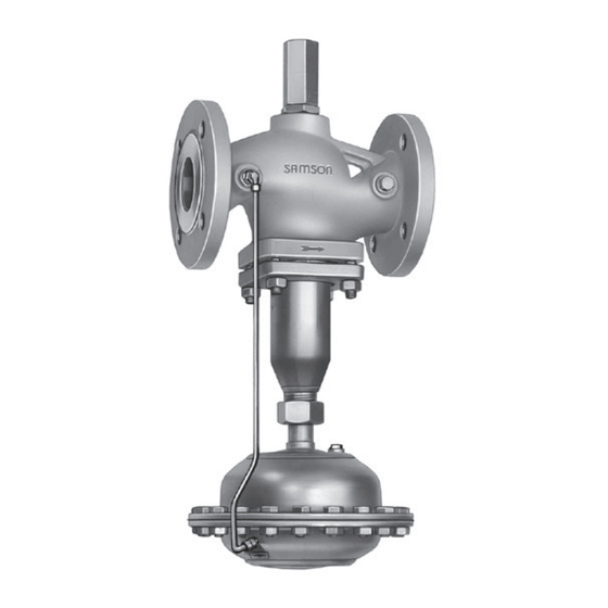
Flow regulator
Hide thumbs
Also See for 42-36:
- Mounting and operating instructions (20 pages) ,
- Mounting and operating instructions (80 pages)

Subscribe to Our Youtube Channel
Related Manuals for Samson 42-36


Summary of Contents for Samson 42-36
- Page 1 EB 3015 EN Translation of original instructions Type 42-36 Flow Regulator Self-operated Regulators Edition October 2023...
- Page 2 Note on these mounting and operating instructions These mounting and operating instructions assist you in mounting and operating the device safely. The instructions are binding for handling SAMSON devices. The images shown in these instructions are for illustration purposes only. The actual product may vary.
-
Page 3: Table Of Contents
Contents Safety instructions and measures ..............1-1 Notes on possible severe personal injury ............1-4 Notes on possible personal injury ..............1-5 Notes on possible property damage .............1-7 Markings on the device ................2-1 Nameplates ....................2-1 Location of the nameplates ................2-2 2.3 Material identification number ..............2-2 2.3.1 Type 2423 Valve ..................2-2 2.3.2... - Page 4 Removal ....................11-1 11.1 Removing the regulator from the pipeline ............11-1 11.2 Removing the actuator from the valve ............11-1 Repairs ....................12-1 12.1 Returning devices to SAMSON ..............12-1 Disposal ....................13-1 Certificates ....................14-1 14.1 Information on the UK sales region .............14-1 Annex......................15-1 15.1 Tightening torques ..................15-1...
-
Page 5: Safety Instructions And Measures
In case operators intend to use the regulators in applications or conditions other than those specified, contact SAMSON. SAMSON does not assume any liability for damage resulting from the failure to use the de- vice for its intended purpose or for damage caused by external forces or any other external factors. - Page 6 − Safety harness, e.g. when working at height − Safety footwear, if applicable ESD (electrostatic discharge) footwear Î Check with the plant operator for details on further protective equipment. Revisions and other modifications Revisions, conversions or other modifications of the product are not authorized by SAMSON. They are performed at the user's own risk and may lead to safety hazards, for example. Fur- thermore, the product may no longer meet the requirements for its intended use. Warning against residual hazards...
- Page 7 Start-up and shutdown procedures fall within the scope of the operator's duties and, as such, are not part of these mounting and operating instructions. SAMSON is unable to make any statements about these procedures since the operative details (e.g. differential pressures and temperatures) vary in each individual case and are only known to the operator.
-
Page 8: Notes On Possible Severe Personal Injury
Safety instructions and measures Referenced documentation The following documents apply in addition to these mounting and operating instructions: − Mounting and operating instructions for e.g. Type 2 N or 2 NI Strainer u EB 1015 − Data sheets for e.g. Accessories · Differential pressure and flow regulators u T 3095 Type 2 N or 2 NI Strainer e.g. -
Page 9: Notes On Possible Personal Injury
Safety instructions and measures 1.2 Notes on possible personal injury WARNING Risk of personal injury due to incorrect operation, use or installation as a result of information on the regulator being illegible. Over time, markings, labels and nameplates on the regulator may become covered with dirt or become illegible in some other way. As a result, hazards may go unno- ticed and the necessary instructions not followed. - Page 10 Î Wear protective clothing, safety gloves and eye protection. Damage to health relating to the REACH regulation. If a SAMSON device contains a substance listed as a substance of very high concern on the candidate list of the REACH regulation, this is indicated on the SAMSON deliv- ery note.
-
Page 11: Notes On Possible Property Damage
The lubricants to be used depend on the regulator material. Unsuitable lubricants may corrode and damage surfaces. Î Only use lubricants approved by SAMSON. When in doubt, consult SAMSON. Risk of leakage and regulator damage due to excessively high or low tightening torques. - Page 12 Î Always install a safety device (e.g. safety excess pressure valve or safety relief valve) in the plant. Note SAMSON's After-sales Service can support you concerning lubricant, tightening torques and tools approved by SAMSON. EB 3015 EN...
-
Page 13: Markings On The Device
Markings on the device 2 Markings on the device Several nameplates are affixed to the device. The nameplates shown were up to date at the ones shown. The nameplates are used to the time of publication of this document. The identify the separate regulator components nameplates on the device may differ from (see section 2.1). -
Page 14: Location Of The Nameplates
Markings on the device 2.2 Location of the nameplates 2.3 Material identification number 2.3.1 Type 2423 Valve See the nameplate (11 for DIN/ANSI ver- Location of the sion, body material) for the material used. nameplate on the regulator For more details on the nameplate, see sec- components tion 2.1. -
Page 15: Design And Principle Of Operation
(1.4) Type 42-36 DoT · This version can also con- is transferred through the hollow plug stem trol or limit the temperature by mounting a (7) past the diaphragm stem (6) to the top double adapter with thermostat. - Page 16 Design and principle of operation Type 2423 Valve balanced by a bellows Type 2426 Actuator Fig. 3-1: Functional diagram for regulators, DN 15 to 250 with balancing bellows EB 3015 EN...
- Page 17 Design and principle of operation Type 2423 Valve balanced by a diaphragm Type 2426 Actuator Fig. 3-2: Functional diagram for regulators, DN 65 to 250 with balancing diaphragm Legend for Fig. 3-1 and Fig. 3-2 Valve body Seat Vent plug (DN 125 15 Screws and larger) Set point adjuster for Plug 16 Diaphragm plate flow rate 11 Coupling nut Balancing bellows 17 Nut...
-
Page 18: Additional Fittings
= Δp ∆p across the valve is calculated as follows: restriction ∆p Minimum differential pressure across the valve in bar ∆p Differential pressure created at the restriction for measuring the flow rate in the regulator restriction · Adjusted flow rate in m³/h Valve flow coefficient in m³/h Fig. 3-3: Installation example: Type 42-36 installed in the flow and return flow pipe EB 3015 EN... -
Page 19: Technical Data
− Set points from 0.05 to 520 m³/h Note − Valve size DN 15 to 250 The Type 42-36 Regulator is not a safety − Pressure ratings from PN 16 to 40 valve. If necessary, a suitable overpressure The regulator is open when relieved of pres- protection must be installed on site in the sure. - Page 20 Noise emissions ings are shown on page 3-10. SAMSON is unable to make general state- ments about noise emissions. The noise emis- Table 3-1: Technical data · All pressures in bar (gauge) Type 2423 Valve · Balanced by a bellows Valve size DN 15 to 100...
- Page 21 Design and principle of operation Table 3-2: K coefficients, x values, flow rate set point ranges for water and max. per- missible differential pressures Δp Type 2423 Valve balanced by a bellows Valve size DN Valve travel 10 mm 16 mm 22 mm coefficient value 0.65 0.55...
- Page 22 Design and principle of operation Table 3-3: Materials · Material numbers according to DIN EN Type 2423 Valve · Balanced by a bellows Pressure rating PN 16 PN 25 PN 16, 25 and 40 Spheroidal graphite Cast iron Cast steel Cast stainless Forged stainless Valve body iron EN-GJS-400- EN-GJL-250...
- Page 23 Design and principle of operation Table 3-4: Dimensions in mm and weights · Type 2423 Valve balanced by a bellows Valve size Length L Height H1 Forged steel – – – Height Other materials Height H 5) 6) (ØD = 285 mm, Actuator (ØD = 225 mm, A = 160 cm²) 2) A = 320 cm²) 3) Weight for PN 16...
- Page 24 Design and principle of operation Dimensional drawings Type 2423 Valve balanced by a bellows Type 2423 Valve, balanced by a diaphragm Ø D V-ring packing Actuator with two diaphragms For the version with a V-ring packing (e.g. for steam) in DN 15 to 100, add 60 mm to the specified dimension for H2. Fig. 3-4: Dimensions 3-10 EB 3015 EN...
-
Page 25: Shipment And On-Site Transport
2. Check the shipment for transportation fore installing the valve into the pipeline. damage. Report any damage to They prevent foreign particles from enter- SAMSON and the forwarding agent (re- ing the valve. fer to delivery note). Î Dispose and recycle the packaging in ac- 3. Determine the weight and dimensions of cordance with the local regulations. -
Page 26: Transporting And Lifting The Regulator
Shipment and on-site transport 4.3 Transporting and lifting the WARNING regulator Risk of lifting equipment tipping over and risk of damage to lifting accessories due to exceeding the rated lifting capacity. DANGER Î Only use approved lifting equipment and Danger due to suspended loads falling. accessories whose minimum lifting ca- Î... -
Page 27: Lifting The Regulator
Shipment and on-site transport Î Protect the piping and any mounted 3. Move the regulator at an even pace to valve accessories against damage. the site of installation. Î The permissible ambient temperature of 4. Install the regulator into the pipeline (see standard regulators is –20 to +80 °C. -
Page 28: Storing The Regulator
Î To keep elastomers in shape and to pre- Î Avoid long storage times. vent cracking, do not bend them or hang Î Contact SAMSON in case of different them up. storage conditions or longer storage Î Store elastomers away from lubricants, times. -
Page 29: Installation
The inlet and outlet lengths vary depending on several variables and process conditions Î Contact SAMSON if the mounting posi- and are intended as recommendations. Con- tion is not as specified above. tact SAMSON if the lengths are significantly shorter than the recommended lengths. - Page 30 − All media above 80 °C moving parts on the actuator or to the − Steam applications control lines. Alternative mounting position, Î Contact SAMSON if the mounting posi- actuator on top tion differs from the standard mounting Balanced by a diaphragm · position.
-
Page 31: Preparation For Installation
If the regulator tends to hunt, we recommend conditions are met: installing a needle valve in the control line in − The valve is clean. addition to the standard SAMSON screw joint with restriction. − The valve, actuator and all piping are not damaged. - Page 32 1 Shut-off valve 5 Pressure gauge (return flow pipe) Compensation chamber (optional) 2 Strainer 6 Shut-off valve 3 Pressure gauge (flow pipe) 7 Motorized valve 4 Flow regulator 8 Needle valve Fig. 5-2: Installation example: Type 42-36 installed in the flow and return flow pipe EB 3015 EN...
-
Page 33: Installation
Risk of regulator damage due to the use of taking into account age, gender and unsuitable tools. physical fitness. Î Only use tools approved by SAMSON Î When the actuator is filled with medium, (see 'Tools' in Annex). take the weight of the medium also into account. -
Page 34: Installing The Regulator
Installation Î Procedure for ready-assembled device NOTICE 3. Lift the regulator using suitable lifting Risk of regulator damage due to exces- equipment to the site of installation. Ob- sively high or low tightening torques. serve the flow direction through the Observe the specified torques when tighten- valve. -
Page 35: Testing The Regulator
Î Drain the process medium from all the The regulator components are delivered by plant sections concerned as well as the SAMSON ready for use. To test the regulator valve. functioning before start-up or putting back the regulator into operation, perform the fol-... -
Page 36: Pressure Test
SAMSON's After-sales Service can support The plant operator is responsible for per- you to plan and perform a leak test for your forming the pressure test. SAMSON's Af- plant. ter-sales Service can support you to plan and perform a pressure test for your plant. -
Page 37: Filling The Plant
Installation 5.4.3 Filling the plant Pressure test without mounted diaphragm actuator Open the shut-off valves slowly over a time Î Depressurize the plant and remove the period of several minutes preferably starting control line. Close any control line con- from the upstream pressure side to fill the nection in the plant by closing the in- plant (all consumers and control lines are stalled shut-off valve or inserting a blank- open). -
Page 38: Insulation
Installation Î A lower set point is adjusted at the con- NOTICE troller and all consumers are open to Risk of regulator damage due to incorrect guarantee a high flow rate. insulation. Î Observe the mesh size of the upstream Î The actuator must be insulated for medi- strainer for the maximum particle size. um temperatures below 0 °C. Use strainers to suit the process medium. -
Page 39: Start-Up
Start-up 6 Start-up DANGER The work described in this section is only to Risk of personal injury due to process me- be performed by personnel appropriately dium escaping. qualified to carry out such tasks. Î Do not start up the regulator until all parts have been mounted. WARNING Before start-up or putting the valve back into Risk of burn injuries due to hot or cold com-... -
Page 40: Start-Up And Putting The Device Back Into Operation
Start-up 6.1 Start-up and putting the 6.2 Starting up the plant device back into operation WARNING 1. Depending on the field of application, Risk of personal injury due to process me- allow the regulator to cool down or dium escaping. warm up to reach ambient temperature Depending on the conditions in the plant in before start up. -
Page 41: Regulation Of Liquids
Start-up 6.2.2 Regulation of steam Note On filling the plant, make sure the restriction Î Warm up the plant very slowly. During (1.4) is open by turning the adjustment this procedure, drain off any condensate screw counterclockwise () as far as it will and vent the plant. Î... - Page 42 Start-up EB 3015 EN...
-
Page 43: Operation
Operation 7 Operation WARNING Immediately after completing start-up or Risk of hearing loss or deafness due to loud placing the regulator back into service (see noise. the 'Start-up' section), the regulator is ready Noise emission (e.g. cavitation) may occur for use. during operation caused by the process me- dium and the operating conditions. -
Page 44: Adjusting The Flow Rate
Operation 4. Based on a closed restriction, turn the re- Note striction screw counterclockwise () to Observe the differential pressure across the adjust this value. Wait until the plant has restriction ∆p of 0.2 bar or 0.5 bar. It settled. If necessary, readjust. restriction is determined by the differential pressure 5. - Page 45 Operation = 0.5 bar · ____ ∆p – – – – ∆p = 0.2 bar restriction restriction Fig. 7-1: Adjustment diagram for Type 2423, balanced by a bellows, DN 15 to 50 EB 3015 EN...
- Page 46 Operation ––––––– ∆p = 0.2 bar · – – – – ∆p = 0.3 bar · ∆p = 0.5 bar • • • • restriction restriction restriction Fig. 7-2: Adjustment diagram for Type 2423, balanced by a bellows, DN 65 and 80 EB 3015 EN...
- Page 47 Operation ––––––– ∆p = 0.2 bar · – – – – ∆p = 0.3 bar · ∆p = 0.5 bar • • • • restriction restriction restriction Fig. 7-3: Adjustment diagram for Type 2423, balanced by a bellows, DN 100 and 125 EB 3015 EN...
- Page 48 Operation ––––––– ∆p = 0.2 bar · – – – – ∆p = 0.3 bar · ∆p = 0.5 bar • • • • restriction restriction restriction Fig. 7-4: Adjustment diagram for Type 2423, balanced by a bellows, DN 150 to 250 EB 3015 EN...
- Page 49 Operation ––––––– ∆p = 0.2 bar · – – – – ∆p ∆p = 0.5 bar = 0.3 bar · • • • • restriction restriction restriction Fig. 7-5: Adjustment diagram for Type 2423, balanced by a diaphragm, DN 65 to 80 EB 3015 EN...
- Page 50 Operation ––––––– ∆p = 0.2 bar · – – – – ∆p = 0.3 bar · ∆p = 0.5 bar • • • • restriction restriction restriction Fig. 7-6: Adjustment diagram for Type 2423, balanced by a diaphragm, DN 100 to 125 EB 3015 EN...
- Page 51 Operation ––––––– ∆p = 0.2 bar · – – – – ∆p = 0.3 bar · ∆p = 0.5 bar • • • • restriction restriction restriction Fig. 7-7: Adjustment diagram for Type 2423, balanced by a diaphragm, DN 150 to 200 EB 3015 EN...
- Page 52 Operation ––––––– ∆p = 0.2 bar · – – – – ∆p = 0.3 bar · ∆p = 0.5 bar • • • • restriction restriction restriction Fig. 7-8: Adjustment diagram for Type 2423, balanced by a diaphragm, DN 250 7-10 EB 3015 EN...
-
Page 53: Malfunctions
Î Remove foreign particles. Foreign particles blocking the plug Î Replace damaged parts. Î Contact SAMSON's After-sales Service. Î Replace the damaged seat and plug. Flow rate exceeds Seat and plug are worn or leak. adjusted set point. - Page 54 For troubleshooting, the conditions, such as installation, process medium, temperature and pressure conditions, must be taken into ac- count. SAMSON's After-sales Service can support you in drawing up an inspection and test plan for your plant. EB 3015 EN...
-
Page 55: Emergency Action
2. Perform troubleshooting (see sec- tion 8.1). 3. Rectify those malfunctions that can be remedied based on the instructions provided here. Contact SAMSON's After-sales Service in all other cases. Putting the regulator back into operation after a malfunction See the 'Start-up' section. - Page 56 EB 3015 EN...
-
Page 57: Servicing
Servicing 9 Servicing WARNING The regulator does not require any mainte- Risk of personal injury due to the regulator nance. Nevertheless, it is subject to natural tipping. wear, particularly at the seat, plug and oper- Î Observe the regulator's center of gravity. ating diaphragm. Depending on the operat- Î... - Page 58 Lifting the regulator without the use of lifting Î Only use tools approved by SAMSON equipment may lead to injuries (back injury (see 'Tools' in Annex). in particular) depending on the weight of the regulator and/or actuator.
- Page 59 Servicing Type 2423 Valve balanced by a bellows Type 2426 Actuator Fig. 9-1: Functional diagram for regulators, DN 15 to 250 with balancing bellows EB 3015 EN...
- Page 60 Servicing Type 2423 Valve balanced by a diaphragm Type 2426 Actuator Fig. 9-2: Functional diagram for regulators, DN 65 to 250 with balancing diaphragm Legend for Fig. 9-1 and Fig. 9-2 Valve body Balancing bellows 14 Differential pressure springs 1.1 Set point adjuster for flow rate 5.1 Balancing diaphragm 15 Bolts, nuts 1.2 Lock nut Diaphragm stem 16 Diaphragm plate 1.3 Cap Plug stem 17 Diaphragm plate nut...
-
Page 61: Preparing The Valve For Service Work
Servicing 9.1 Preparing the valve for 9.2 Installing the regulator service work after service work 1. Lay out the necessary material and tools Î Put the regulator back into operation (see to have them ready for the service work. the 'Start-up' section). Make sure the re- quirements and conditions for start-up or 2. -
Page 62: Service Work
Servicing 9.3 Service work 9.3.1 Replacing the actuator Î Before performing any service work, Î See Fig. 9-1 and Fig. 9-2 preparations must be made to the regu- Removing the actuator lator (see section 9.1). 1. Put the regulator out of operation (see Î After all service work is completed, check the 'Decommissioning' section). the regulator before putting it back into 2. -
Page 63: Replacing The Seat And Plug
Do not exchange the operating diaphragm (12) from the diaphragm plate (16). in an FDA-compliant regulator version. SAMSON's After-sales Service can support Mounting the operating diaphragm you to perform such service work. 1. Place a new operating diaphragm (12) onto the diaphragm plate (16) (ensuring... -
Page 64: Ordering Spare Parts And Operating Supplies
6. Put the regulator back into operation (see the 'Start-up' section). 9.4 Ordering spare parts and operating supplies Contact your nearest SAMSON subsidiary or SAMSON's After-sales Service for infor- mation on spare parts, lubricants and tools. Spare parts See Annex for details on spare parts. Lubricant Contact SAMSON's After-sales Service for more information on lubricants. -
Page 65: Decommissioning
Decommissioning 10 Decommissioning WARNING The work described in this section is only to Risk of hearing loss or deafness due to loud be performed by personnel appropriately noise. qualified to carry out such tasks. Noise emission (e.g. cavitation) may occur during operation caused by the process me- dium and the operating conditions. - Page 66 Decommissioning To decommission the regulator for service work or disassembly, proceed as follows: 1. Close the shut-off valve (1) on the up- stream side of the regulator. 2. Close the shut-off valve (6) on the down- stream side of the regulator. 3. Depressurize the plant. 4. Completely drain the pipelines and valve.
-
Page 67: Removal
Removal 11 Removal 11.1 Removing the regulator from the pipeline The work described in this section is only to be performed by personnel appropriately 1. Support the regulator to hold it in place qualified to carry out such tasks. when separated from the pipeline (see the 'Shipment and on-site transport' sec- WARNING tion). - Page 68 11-2 EB 3015 EN...
-
Page 69: Repairs
Î Do not perform any repair work on your from our website at own. u www.samsongroup.com > Service Î Contact SAMSON's After-sales Service & Support > After-sales Service. for repair work. After checking your registration, we will send you a return merchandise authori- zation (RMA). - Page 70 12-2 EB 3015 EN...
-
Page 71: Disposal
Disposal 13 Disposal SAMSON is a producer registered at the following European institution u https://www.ewrn.org/ national-registers/national- registers. WEEE reg. no.: DE 62194439/FR 025665 Î Observe local, national and internation- al refuse regulations. Î Do not dispose of components, lubricants and hazardous substances together with your other household waste. Note We can provide you with a recycling passport according to PAS 1049... - Page 72 13-2 EB 3015 EN...
-
Page 73: Certificates
− EU declaration of conformity in 2016, STATUTORY INSTRUMENTS, compliance with Pressure Equipment 2016 No. 1105 (UKCA marking). It does Directive 2014/68/EU on page 14-2. not apply to Northern Ireland. − EU declaration of conformity in compliance with Machinery Directive Importer 2006/42/EC for Type 42-36 Regulator SAMSON Controls Ltd on page 14-8. Perrywood Business Park Honeycrock Lane − Declaration of incorporation in Redhill, Surrey RH1 5JQ compliance with Machinery Directive 2006/42/EC for Type 2423 Valve and Phone: +44 1737 766391 Type 2426 Actuator on page 14-8. - Page 74 DIN EN, body, EN-GJS-400-18-LT and CC499K, DN 50, PN 25, fluids G2, L2, L1 2447 (44-7) 2448 (44-8) 2449 (44-9) Revision 00 Classification: Public · SAMSON AKTIENGESELLSCHAFT · Weismuellerstrasse 3 · 60314 Frankfurt am Main, Germany Page 1 of 3 14-2 EB 3015 EN...
- Page 75 Liquids according to Article 4(1)(c.ii) Gases according to Article 4(1)(c.i), second indent Liquids according to Article 4(1)(c.ii), second indent Revision 00 Classification: Public · SAMSON AKTIENGESELLSCHAFT · Weismuellerstrasse 3 · 60314 Frankfurt am Main, Germany Page 2 of 3 EB 3015 EN 14-3...
- Page 76 Norbert Tollas i.V. Peter Scheermesser Senior Vice President Director Global Operations Product Maintenance & Engineered Products Revision 00 Classification: Public · SAMSON AKTIENGESELLSCHAFT · Weismuellerstrasse 3 · 60314 Frankfurt am Main, Germany Page 3 of 3 14-4 EB 3015 EN...
- Page 77 ANSI, body, A216 WCC and A351 CF8M, NPS 2½-6, Class 150, all fluids ANSI, body, A216 WCC and A351 CF8M, NPS 1½-6, Class 300, all fluids Revision 00 Classification: Public · SAMSON AKTIENGESELLSCHAFT · Weismuellerstrasse 3 · 60314 Frankfurt am Main, Germany Page 1 of 3 EB 3015 EN...
- Page 78 DIN EN, body, EN-GJS-400-18-LT, DN 100-150, PN 25, fluids G2, L2, L1 DIN EN, body, 1.0619, DN 100-250, PN 16, all fluids Revision 00 Classification: Public · SAMSON AKTIENGESELLSCHAFT · Weismuellerstrasse 3 · 60314 Frankfurt am Main, Germany Page 2 of 3 14-6...
- Page 79 Norbert Tollas i.V. Peter Scheermesser Senior Vice President Director Global Operations Product Maintenance & Engineered Products Revision 00 Classification: Public · SAMSON AKTIENGESELLSCHAFT · Weismuellerstrasse 3 · 60314 Frankfurt am Main, Germany Page 3 of 3 EB 3015 EN 14-7...
- Page 80 Stephan Giesen Director Director Product Life Cycle Management and ETO Product Management Development for Valves and Actuators Revision no. 00 Classification: Public · SAMSON AKTIENGESELLSCHAFT · Weismüllerstraße 3 · 60314 Frankfurt, Germany Page 1 of 1 14-8 EB 3015 EN...
- Page 81 November 2022 Norbert Tollas Peter Scheermesser Senior Vice President Director Global Operations Product Maintenance & Engineered Products Revision 00 Classification: Public · SAMSON AKTIENGESELLSCHAFT · Weismüllerstrasse 3 · 60314 Frankfurt am Main, Germany Page 1 of 1 EB 3015 EN 14-9...
- Page 82 November 2022 Norbert Tollas Peter Scheermesser Senior Vice President Director Global Operations Product Maintenance & Engineered Products Revision 00 Classification: Public · SAMSON AKTIENGESELLSCHAFT · Weismüllerstrasse 3 · 60314 Frankfurt am Main, Germany Page 1 of 1 14-10 EB 3015 EN...
- Page 83 The Supply of Machinery (Safety) Regulations 2008 For the following product: Type 42-36 Flow Regulator consisting of Type 2423 Valve and Type 2426 Actuator We hereby declare that the machinery mentioned above complies with all applicable requirements stipulated in Directive 2008 No. 1597 The Supply of Machinery (Safety) Regulations 2008.
- Page 84 Frankfurt am Main, 27 April 2022 Stephan Giesen Peter Scheermesser Director Director Product Management Product Maintenance & Engineered Products Revision 00 Classification: Public · SAMSON AKTIENGESELLSCHAFT · Weismuellerstrasse 3 · 60314 Frankfurt am Main, Germany Page 1 of 1 14-12 EB 3015 EN...
- Page 85 Frankfurt am Main, 12 May 2022 Stephan Giesen Peter Scheermesser Director Director Product Management Product Maintenance & Engineered Products Revision 00 Classification: Public · SAMSON AKTIENGESELLSCHAFT · Weismuellerstrasse 3 · 60314 Frankfurt am Main, Germany Page 1 of 1 EB 3015 EN 14-13...
- Page 86 14-14 EB 3015 EN...
-
Page 87: Annex
Nuts and bolts (15) – 40 to 640 cm² Control line connection (17) – 40 to 640 cm² 15.2 Lubricant SAMSON's After-sales Service can support you concerning lubricants and sealants ap- proved by SAMSON. 15.3 Tools SAMSON's After-sales Service can support you concerning tools approved by SAMSON. -
Page 88: Spare Parts
Annex 15.5 Spare parts Legend for Fig. 15-1 and Fig. 15-2 Bellows 34 Flange Restriction 35 Screw plug 12 Balancing screw 46 Graphite seal on metal core 16 Seat 51 Stud 17 Plug 52 Hex nut 20 Body 81 Cap 21 Guide cap 82 Hex nut 22 Label 94 Set point adjuster 24 Compression spring 132 O-ring... - Page 89 Annex Fig. 15-2: Type 2423 Valve, DN 125 to 250 · Balanced by a bellows EB 3015 EN 15-3...
- Page 90 Annex Legend for Fig. 15-3 Restriction 22 Label Compression spring 27 Cover 10 Diaphragm plate 34 Ring 11 Diaphragm 46 Seal 12 Castle nut 51 Stud 13 Washer 52 Hex nut 14 Plug stem 53 Screw plug 16 Seat 81 Cap 18 Plug 82 Hex nut 19 Screw 94 Set point adjuster...
- Page 91 Annex Legend for Fig. 15-4 Restriction 42 Clamping disk Seat 46 Seal Diaphragm case 47 Diaphragm 11 Cap 49 Screw plug 12 Body 50 Screw plug 17 Label 51 Stud 19 Plug 52 Hex nut 21 Nipple 53 Hex nut 24 Nut 54 Hex nut 38 Diaphragm plate 57 O-ring...
- Page 92 Annex Legend for Fig. 15-5 Diaphragm case 15 Diaphragm Diaphragm case 17 Hex bolt Screw joint with restriction 19 Hex nut 23 Hanger Diaphragm stem 26 Compression spring 13 Diaphragm plate 27 Compression spring 14 Washer Fig. 15-5: Type 2426 Diaphragm Actuator, DN 15 to 250 15-6 EB 3015 EN...
-
Page 93: After-Sales Service
E-mail address You can reach our after-sales service at aftersalesservice@samsongroup.com. Addresses of SAMSON AG and its subsid- iaries The addresses of SAMSON, its subsidiaries, representatives and service facilities world- wide can be found on our website (u www.samsongroup.com) or in all... - Page 94 15-8 EB 3015 EN...
- Page 95 EB 3015 EN...
- Page 96 EB 3015 EN...
- Page 97 EB 3015 EN...
- Page 98 EB 3015 EN SAMSON AKTIENGESELLSCHAFT Weismüllerstraße 3 · 60314 Frankfurt am Main, Germany Phone: +49 69 4009-0 · Fax: +49 69 4009-1507 samson@samsongroup.com · www.samsongroup.com...
Need help?
Do you have a question about the 42-36 and is the answer not in the manual?
Questions and answers