Samson 46-7 Mounting And Operating Instructions
Self-operated regulators flow and differential pressure or pressure regulators
Hide thumbs
Also See for 46-7:
- Mounting and operating instruction (36 pages) ,
- Mounting and operating instructions (48 pages)
Table of Contents

Related Manuals for Samson 46-7


Summary of Contents for Samson 46-7
- Page 1 EB 3131 EN Translation of original instructions Type 47-1 with manual adjuster Type 46-7 Type 47-5 Types 46-7, 47-5 and 47-1 Self-operated Regulators Flow and Differential Pressure or Pressure Regulators Edition September 2020...
- Page 2 Î For the safe and proper use of these instructions, read them carefully and keep them for later reference. Î If you have any questions about these instructions, contact SAMSON‘s After-sales Service Department (aftersalesservice@samson.de). The mounting and operating instructions for the devices are included in the scope of delivery.
-
Page 3: Table Of Contents
Contents Safety instructions and measures ..............5 Notes on possible severe personal injury ............8 Notes on possible personal injury ..............9 Notes on possible property damage ..............11 Markings on the device ................13 Material numbers ..................13 Design and principle of operation ..............14 Mounting parts ....................17 Versions ......................17 Technical data .....................18 Measures for preparation ................22... - Page 4 Contents Malfunctions ....................36 Decommissioning and removal ..............39 Decommissioning ..................40 Disposal ......................40 Annex......................40 10.1 After-sales service ..................40 10.2 Certificates ....................41 EB 3131 EN...
-
Page 5: Safety Instructions And Measures
Therefore, operators must ensure that the regulator and actuator are only used in operating conditions that meet the specifications used for sizing the devices at the ordering stage. In case operators intend to use the devices in other applications or conditions than specified, contact SAMSON. SAMSON does not assume any liability for damage resulting from the failure to use the de- vice for its intended purpose or for damage caused by external forces or any other external factors. Î Refer to the technical data and nameplate for limits and fields of application as well as possible uses. - Page 6 Î Observe safety measures for handling the device as well as fire prevention and explosion protection measures. Safety features The Types 46-7, 47-5 and 47-1 Regulators do not have any special safety features. When relieved of pressure and with open restriction, the regulators are opened by the force of the set point springs. Responsibilities of the operator The operator is responsible for proper operation and compliance with the safety regulations.
- Page 7 Start-up and shutdown procedures fall within the scope of the operator's duties and, as such, are not part of these mounting and operating instructions. SAMSON is unable to make any statements about these procedures since the operative details (e.g. differential pressures and temperatures) vary in each individual case and are only known to the operator.
-
Page 8: Notes On Possible Severe Personal Injury
Safety instructions and measures 1.1 Notes on possible severe personal injury DANGER Risk of bursting in pressure equipment. Regulators and pipelines are pressure equipment. Improper opening can lead to device components bursting. Î Observe the maximum permissible pressure for regulator and plant. Î... -
Page 9: Notes On Possible Personal Injury
Safety instructions and measures 1.2 Notes on possible personal injury WARNING Crush hazard arising from moving parts. The regulator contains moving parts (actuator and plug stem), which can injure hands or fingers if inserted into the valve. Î Do not insert hands or fingers between the set point springs while the regulator is in operation. Î Before performing any work on the regulator, depressurize the plant. Disconnect or shut off the external control line. Risk of personal injury through incorrect operation, use or installation as a result of information on the regulator being illegible. - Page 10 Î Wear protective clothing and safety gloves. Damage to health relating to the REACH regulation. If a SAMSON device contains a substance which is listed as being a substance of very high concern on the candidate list of the REACH regulation, this circumstance is indicat- ed on the SAMSON delivery note.
-
Page 11: Notes On Possible Property Damage
Safety instructions and measures 1.3 Notes on possible property damage NOTICE Risk of regulator damage due to contamination (e.g. solid particles) in the pipeline. The plant operator is responsible for cleaning the pipelines in the plant. Î Flush the pipelines before start-up. Risk of regulator damage due to unsuitable medium properties. - Page 12 Î The lubricants to be used depend on the regulator material. Unsuitable lubricants may corrode and damage surfaces. Î Only use lubricants approved by SAMSON. When in doubt, consult SAMSON. Î Risk of regulator damage due to the use of unsuitable tools.
-
Page 13: Markings On The Device
Markings on the device 2 Markings on the device 1 Material number 2 Model number 3 Date of manufacture 5 Pressure rating PN or Class Differential pressure set point range in bar or 7 Type designation 8 Flow rate set point range in m³/h or gal/min 9 Maximum permissible temperature in °C or °F Max. permissible differential pressure ∆p in bar or psi... -
Page 14: Design And Principle Of Operation
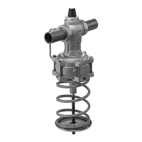
The combined regulators basically consist of nal is always used to control the regulator. a valve body (1) with a balanced plug as Type 46-7 and Type 47-5 well as a closing actuator with two operating To control the flow rate, the low pressure diaphragms. The regulators are used to limit downstream of the restriction (1.2) is trans-... - Page 15 Design and principle of operation Type 47-1 and Type 46-7 Type 46-7 DN 15 to 32, set point range 0.2 (–) A to 0.6 bar and 0.2 to 1 bar, with (+) B manual adjuster and scale for Δp set point adjustment. (–) C (+) D Type 47-5 Fig. 2: Type 46-7 and Type 47-5 Flow and Differential Pressure Regulator and manual adjuster EB 3131 EN...
- Page 16 Design and principle of operation Type 47-1 Flanged body Fig. 3: Type 47-1 Flow and Differential Pressure or Pressure Regulator EB 3131 EN...
-
Page 17: Mounting Parts
˙ V downstream of the restriction (1.2) is turn flow pipe of a district heating station. transmitted through a hole in the plug (3) to − Type 46-7 · With adjustable flow rate the top diaphragm chamber A. and differential pressure set point · With The high pressure of Δp is transmitted internal overload protection (excess pres-... -
Page 18: Technical Data
Design and principle of operation 3.3 Technical data Note Flow and differential pressure regulators with Min. differential pressure Δp Type 5824 or Type 5825 Electric Actuator or The minimum required differential pressure Type 2430 Control Thermostat. Δp across the regulator is calculated as In these regulators, the signal of an electric follows: control device can be applied to achieve ·... - Page 19 Max. permissible differential pressure ∆p /20 bar 16 bar 2) across the regulator Max. permissible temperature Liquids: 130 °C /150 °C · Air and nitrogen: 150 °C Pressure above adjusted diff. pressure set point at which internal excess pressure 0.5 bar limiter responds (Types 46-7, 47-5) · Conformity Differential pressure set point ranges 0.2 to 0.6 bar 0.2 to 0.5 bar Type 46-7 and Type 47-1: continuously 0.2 to 1 bar 0.2 to 1 bar adjustable 0.5 to 2 bar 0.5 to 2 bar...
- Page 20 Design and principle of operation Table 5: Regulator with connecting parts · Dimensions in mm Valve size DN 15 DN 20 DN 25 DN 32 DN 40 DN 50 With welding ends Type 46-7 Weight, 12.5 approx. Type 47-1 Type 47-5 With threaded ends Male thread A G ½ G ¾ G 1 G 1¼...
- Page 21 Design and principle of operation Dimensional drawings ØD ØD Version with manual adjuster for flow rate set point adjustment Types 46-7, 47-1 · DN 15 to 50 with welding ends Types 46-7, 47-1 · DN 15 to 32, set point ranges 0.2 to 0.6 and 0.2 to 1 bar with welding ends Note The dimensions and weights of valves with flanged bodies (DN 32, 40 and 50) are the same as valves with screwed-on flanges. ØD Type 47-5 · With flanged valve body...
-
Page 22: Measures For Preparation
2. Dispose of the packaging in accordance − Observe the storage instructions. with the valid regulations. − Avoid long storage times. − Contact SAMSON in case of different storage conditions or long storage periods. Note We recommend regularly checking the de- vice and the prevailing storage conditions during long storage periods. -
Page 23: Preparation For Installation
− We recommend a storage temperature of 15 °C for elastomers. − Store elastomers away from lubricants, chemicals, solutions and fuels. SAMSON's After-sales Service can provide more detailed storage instructions on re- quest. EB 3131 EN... -
Page 24: Mounting And Start-Up
− Either heat the regulator or remove it from − Install a strainer upstream of the regula- the plant and completely drain the residual tor (see section 5.2). medium. Type 46-7 and Type 47-5 in the return flow pipe – ± Type 47-1 in the – + flow pipe –... -
Page 25: Additional Fittings
3 x DN 3 x DN Strainer A strainer installed upstream in the flow pipe holds back any dirt or other foreign particles carried along by the medium. For example, the SAMSON Type 1 NI Strainer is suitable min. (u T 1010). 3 x DN − Do not use the strainer to permanently filter the process medium. − Install the strainer upstream of the regu- Control lator. -
Page 26: Putting The Regulator Into Operation
Mounting and start-up Correct Connection at the top – incorrect position Connection at the side – optimal Connection at the bottom – incorrect position Fig. 6: Control line connection, depending on how the pipeline is routed 5.3 Putting the regulator into Pressure testing the plant operation All plant components must be designed for the test pressure. -
Page 27: Operation
6.1 Adjusting the set points Screw cap (18) back on. 8. Lead-seal the set point setting at set point 6.1.1 Flow control screw (17) and cap (18). Î Type 46-7 and Type 47-1: Adjust the Note maximum differential pressure at the reg- ulator (see section 6.1.2). The set point can be directly adjusted in the version with manual adjuster. - Page 28 1.2 Restriction Seat Set point spring (differential pressure) Spring plate 10 Set point adjuster (differential pressure) 16 Lock nut 17 Set point screw (flow rate, SW 4) 18 Cap 19 Manual adjuster (differential pressure) Fig. 7: Flow rate and differential pressure control using Type 46-7 and Type 47-1 EB 3131 EN...
- Page 29 Mounting and start-up Table 6: Flow rate set point range for water in m³/h Valve size DN 1) 1) coefficient 12.5 16/20 20/25 2) 2) Set point range in 0.6 to 0.8 to 0.8 to 2 to 3 to 4 to – m³/h with a diff. 14.1 3) 3)
-
Page 30: Differential Pressure Control
0.033 bar in the range from 0.2 to 1 bar and by approx. 0.02 bar in the range from Note 0.2 to 0.6 bar. The differential pressure can only be adjust- ed on the Type 46-7 and Type 47-1 Regula- NOTICE tors. The differential pressure of the Risk of regulator malfunction due to incorrect Type 47-5 Regulator is fixed. setting. A scale value below 1 may lead to incorrect 1. -
Page 31: Servicing
(chemical) burns. − If possible, drain the process medium from all the plant sections affected and the regu- lator. SAMSON's After-sales Service can support − Wear protective clothing, safety gloves and you in drawing up an inspection and test eye protection. - Page 32 Parts that are too loose may cause leakage. Observe the tightening torques specified in section 7.3. Note The regulator was checked by SAMSON before it left the factory. − The product warranty becomes void if service or repair work not described in these instructions is performed without prior agreement by SAMSON's After-sales Service.
-
Page 33: Cleaning And Replacing The Plug
1. Put the regulator out of operation (see DN 32 to 50: insert the plug followed by section 9.1). the stopper (25) of the plug. Observe the 2. For Type 46-7 and Type 47-1, tightening torques specified in sec- completely relieve the tension from the tion 7.3. set point spring (8) by turning the set 3. -
Page 34: Replacing The Diaphragm
1. Put the regulator out of operation (see 6. Fasten the external control lines (13, 14). section 9.1). 7. Put the regulator into operation (see sec- 2. For Type 46-7 and Type 47-1, complete- tion 5.3). ly relieve the tension from the set point spring (8) by turning counterclockwise (). - Page 35 Servicing Version with manual adjuster Assembly 1. Push the assembly, consisting of the new Disassembly diaphragm (6.1) together the diaphragm 1. Put the regulator out of operation (see plates, set point spring (8) and support section 9.1). (21), over the spindle (20) into the bot- 2.
-
Page 36: Tightening Torques
Defective devices can be returned to can be restored following the recommended action. Special tools may be required for re- SAMSON for repair. Proceed as follows to return devices to SAMSON: pair work. 1. Put the regulator out of operation (see Exceptional operating and installation condi- section 9). - Page 37 Î Remove foreign particles. Foreign particles blocking the plug Î Replace damaged parts. Î Contact SAMSON's After-sales Service. Î Replace the damaged seat and plug. Seat and plug are worn or leak. Î Contact SAMSON's After-sales Service. Flow rate or Î...
- Page 38 Loud noises High flow velocity, cavitation. Î Install larger regulator, if necessary. Leakage at the actua- Defective operating diaphragm Î Replace damaged diaphragm. Note Contact SAMSON's After-sales Service for malfunctions not listed in the table and when the malfunction cannot be remedied as described. EB 3131 EN...
-
Page 39: Decommissioning And Removal
Decommissioning and removal 9 Decommissioning and WARNING removal Risk of burn injuries due to hot or cold com- ponents and pipeline. Regulator components and the pipeline may DANGER become very hot or cold. Risk of burn inju- Risk of bursting in pressure equipment. ries. -
Page 40: Decommissioning
Addresses of SAMSON AG and its subsid- ambient temperature. iaries 4. Depressurize the plant sections connect- The addresses of SAMSON, its subsidiaries, ed through the control line. representatives and service facilities 5. Unscrew the control line. worldwide can be found on our website 6. -
Page 41: Certificates
Annex 10.2 Certificates The EU declarations of conformity are in- cluded on the next pages. EB 3131 EN... - Page 42 Modul H/Module H, Nr./No. / N° CE-PED-H-SAM 001-13-DEU-rev-A SAMSON erklärt in alleiniger Verantwortung für folgende Produkte:/For the following products, SAMSON hereby declares under its sole responsibility: Ventile für Druck-, Differenzdruck-, Temperatur- und Volumenstromregler/Valves for pressure, temperature, flowregulators and differential pressure regulators Typ 2336, 2373, 2375, 44-1B, 44-2, 44-3, 44-4, 44-6B, 44-9, 45-1, 45-2, 45-3, 45-4, 45-6, (Erz.-Nr.
- Page 43 2333 (Erz.-Nr./Model No. 2333), 2334 (2334), 2335 (2335), 2336, 2373, 2375, 44-0B, 44-1B, 44-2, 44-3, 44-6B, 44-7, 44-8, 45-1, 45-2, 45-3, 45-4, 45-5, 45-6, 2468, 2478 (2720), 45-9, 46-5, 46-6, 46-7, 46-9, 47-1, 47-4, 47-5, 47-9, 2487, 2488, 2489, 2491, 2494, 2495 (2730), 2405, 2406, 2421 (2811), 2392, 2412 (2812), 2114 (2814), 2417 (2817), 2422 (2814), 2423 (2823) die Konformität mit nachfolgender Anforderung/the conformity with the following requirement.
- Page 44 EB 3131 EN SAMSON AKTIENGESELLSCHAFT Weismüllerstraße 3 · 60314 Frankfurt am Main, Germany Phone: +49 69 4009-0 · Fax: +49 69 4009-1507 samson@samson.de · www.samson.de...
Need help?
Do you have a question about the 46-7 and is the answer not in the manual?
Questions and answers