Table of Contents
Advertisement
DIRECT DIGITIZER
SKR 4000
User Manual
Document Version: 00
Document ID: ACNNBA01EN00
Release Date: 2019-05-08
Before operating, please read this user manual and pay attention to all safety precautions.
Please ensure that this user's manual is properly maintained so that it can be accessed at any time
(reserve).
Please use it correctly on the basis of full understanding of the content.
E
Advertisement
Table of Contents

Related Manuals for Konica Minolta SKR 4000


Summary of Contents for Konica Minolta SKR 4000
- Page 1 DIRECT DIGITIZER SKR 4000 User Manual Document Version: 00 Document ID: ACNNBA01EN00 Release Date: 2019-05-08 Before operating, please read this user manual and pay attention to all safety precautions. Please ensure that this user's manual is properly maintained so that it can be accessed at any time (reserve).
- Page 3 Please take time to read user manual to utilize the product effectively. We hope you enjoy the experience with SKR 4000. Notes on usage and management of the equipment Read all of the instructions in user manual before operation.
- Page 4 No part of this publication may be reproduced in any form or by any means without the written permission of KONICA. The information contained herein is designed only for use with KONICA SKR 4000. Trademarks The KONICA name and KONICA logo are registered trademarks of KONICA MINPLTA, INC.
- Page 5 This symbol indicates the name and address of manufacturers. Labels and markings on the equipment The contents of the labels and markings on SKR 4000 product are indicated below: ICON MEANING Caution: please refer to the instructions in user manual.
- Page 6 SKR 4000 DIRECT DIGITIZER User Manual This symbol is used to identify the manufacture series number which is after, below or adjacent to the symbol. The series number of KONICA products is usually made of thirteen digits as shown below:...
- Page 7 Package symbol, keep away from sunlight. Package symbol, keep dry. This symbol indicates the humidity limits. Keep the product up right Do not roll the transportation package. This symbol indicates stacking limit number. Type-B applied part IPX1 for working surface only KONICA MINOLTA, INC..………….…………………………………………………………………………………………………… ……………….………..5...
-
Page 8: Table Of Contents
SKR 4000 DIRECT DIGITIZER User Manual Contents ........................10 SAFETY 1.1. Safety precautions..........................10 1.2. Notes for Using..........................15 ..................18 GENERAL DESCRIPTION 2.1. Scope..............................18 2.2. Model..............................18 2.3. Characteristic...........................18 2.4. Intended use/ essential performance/ application specification........19 Intended use ..........................19 2.4.1. - Page 9 Inner2 Mode ..........................50 4.1.2. Freesync Mode ........................... 52 4.1.3. 4.2. Connection Build..........................53 4.3. Panel Configuration........................54 4.4. Correction and Calibration Template Generation..............55 Pre-offset Template Generation ....................55 4.4.1. Gain Calibration Template Generation ..................57 4.4.2. KONICA MINOLTA, INC..………….…………………………………………………………………………………………………… ……………….………..7...
- Page 10 SKR 4000 DIRECT DIGITIZER User Manual Defect Correction Template Generation ................... 58 4.4.3. 4.5. Image Check and upload......................60 Local Image Check ........................60 4.5.1. Panel Image Upload ........................61 4.5.2. 4.6. Defect Template Check and Modification................61 Defect Template Check ......................62 4.6.1.
- Page 11 Contents ....................86 TROUBLE SHOOTING ..................87 SERVICE INFORMATION 7.1. Product Lifetime..........................87 7.2. Regular Inspection and Maintenance..................87 7.3. Repair..............................87 7.4. Replacement Parts Support......................87 ............88 APPENDIX A INFORMATION OF MANUFACTURES KONICA MINOLTA, INC..………….…………………………………………………………………………………………………… ……………….………..9...
-
Page 12: Safety
To avoid the risk of electric shock, this product must only be connected to power supply with protective earth. Not doing so may result in fire or electric shock. Do not connect the adapter cord when connect the panel to patient. KONICA MINOLTA, INC..………….…………………………………………………………………………………………………… …………….….………..10... - Page 13 Never use alcohol, ether and other flammable cleaning agent for safety. Never use methanol, benzene and acid because they would corrode the equipment. Don’t dip the product into liquid. Please make sure that surface & plugs are dry before turning on. KONICA MINOLTA, INC..………….…………………………………………………………………………………………………… ……………….………..11...
- Page 14 SKR 4000 DIRECT DIGITIZER User Manual Otherwise, it may result in fire or electric shock. Clean the plug of the power cord periodically by unplugging it from the AC outlet and removing dust or dirt from the plug, its periphery and AC outlet with a dry cloth.
- Page 15 Otherwise, the internal image sensor may be damaged and image may be incorrect. Patients stand on the product temporarily, and the intended weight can be 135kg. Based on the internal TFT character, cannot load the dynamic forces due to loading from persons KONICA MINOLTA, INC..………….…………………………………………………………………………………………………… ……………….………..13...
- Page 16 SKR 4000 DIRECT DIGITIZER User Manual <Load Limit> Uniform load:135 kg over the whole area of the surface. Local load:100 kg on an area 4 cm diameter. Be sure to use the product on flat surface so it would not bend.
-
Page 17: Notes For Using
It’s strongly recommended to remove battery from panel if panel is not used more than 5 days. If battery stores for a long time, it should be charged (30% to 50%) every 3 month or charged (50% to 70%) every 6 month. KONICA MINOLTA, INC..………….…………………………………………………………………………………………………… ……………….………..15... - Page 18 SKR 4000 DIRECT DIGITIZER User Manual Contact with the patients parts cleaning, disinfection and sterilization After every examination, wipe the patient contact surfaces with nonflammable disinfectants to prevent the risk of infection. For details on how to sterilize, consult a specialist.
- Page 19 SKR 4000 DIRECT DIGITIZER User Manual ..................18 GENERAL DESCRIPTION 2.1. Scope..............................18 2.2. Model..............................18 2.3. Characteristic...........................18 2.4. Intended use/ essential performance/ application specification........19 2.5. Essential performance........................19 2.6. The relative position between patient and detector.............. 20 2.7. Product Components........................20 2.8.
-
Page 20: General Description
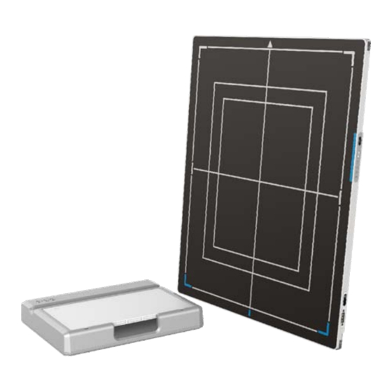
General Description 2. General Description SKR 4000 is a cassette-size wireless X ray direct digitizer based on amorphous silicon thin- film transistor technologies. It is developed to provide the highest quality of radiographic image, which contains an active matrix of 2304×2800 with 150um pixel pitch. The greatest feature is SKR 4000 supports wireless communication between panel and Workstation. -
Page 21: Intended Use/ Essential Performance/ Application Specification
IEC60601-2-63. 2.5. Essential performance According to the SKR 4000 series intended use and the result of risk management, getting imaging and function of data transmission is defined as essential performance. Getting qualified dark image proves that essential performance does not influence intended use. -
Page 22: The Relative Position Between Patient And Detector
Otherwise, the image is prone to abnormal light lines. 2.7. Product Components SKR 4000 comes with both DC power supply and battery package. Once powered on, it would build a connection with Workstation through Ethernet cable (only for service) or Wireless connection. - Page 23 General Description 1 pcs Medical Adapter DC 24V 2 pcs Battery Battery pack Ethernet Cable 1pcs (Only for service) 3.5 m 1pcs Gigabit Ethernet Cable 1 pcs AC Power Cable KONICA MINOLTA, INC..………….…………………………………………………………………………………………………… ….…………….………..21...
-
Page 24: Components Description
SKR 4000 DIRECT DIGITIZER User Manual 1 pcs DC Power Cable 3.5 m Battery Charger 1pcs 1pcs Gain correction data CD-Rom Defect correction map Manual 2.8. Components Description 2.8.1. Detector C DE F ..............................KONICA MINOLTA, INC. -
Page 25: Battery
Detector indicator of control panel Power Button Power button of control panel Mode Button Mode switch Antenna Antenna 2.8.2. Battery Item Name Description Battery Label Battery Interface 8 Pin Battery connector Pilot Pin Indicator Installation direction indicator KONICA MINOLTA, INC..………….…………………………………………………………………………………………………… ….…………….………..23... -
Page 26: Battery Charger
SKR 4000 DIRECT DIGITIZER User Manual 2.8.3. Battery Charger Item Name Description Battery Interface A 8 Pin Battery connector Battery Interface B 5 Pin Battery connector Battery Interface C 5 Pin Battery connector Indicator The indicator definition is as follow... -
Page 27: Product Specification
Two or more battery charging at the same time is prohibited, if charging at the same time, the charger will automatically stop. 2.9. Product Specification 2.9.1. Detector Item Specification Model SKR 4000 Image Sensor a-Si (Amorphous Silicon) TFT 150 μm Pixel Size Active Array 2304 x 2800 Active Area (H x V) 345.6mm x 420mm... -
Page 28: Battery
SKR 4000 DIRECT DIGITIZER User Manual Power Consumption Max. 18W Dimension (L × W × H) 460 x 384 x 15 mm Weight (with one battery) 3.43 kg Image Transfer Wireless : IEEE802.11a/b/g/n/ac 802.11b: Max. 11Mbps 802.11a/g: Max. 54Mbps Data Transmission Rate (Wireless) 802.11n: Max. -
Page 29: Battery Charger
The product must be used with the approved adaptor whose CB certificate number is SG PSB-MD- 00191. 2.9.5. AP Router (Optional) SKR 4000 do not include AP Router. Users can choose AP Router as they wish, however specification below is a requirement. Item... -
Page 30: Wireless Communication
SKR 4000 DIRECT DIGITIZER User Manual 802.11b: Max. 11Mbps 802.11a/g: Max. 54Mbps Wireless Data Rate 802.11n: Max. 300Mbps (MIMO 2x2) 802.11ac: Max. 867Mbps(MIMO 2x2) 2.9.6. Wireless Communication Item Description Wireless Standard IEEE802.1a/b/g/n/ac 2.4G: 2.412 ~ 2.4835 GHz 11: (Ch. 1-11) – United States 13: (Ch. -
Page 31: Mechanical Outlines
Operating 5~35℃ <1k/min 10%~90% RH 700~1060hPa (1kp=1.0197E-5Pa) <10kp/min Storage -20~55℃ <1k/min 5%~95% RH 700~1060hPa (1kp=1.0197E-5Pa) The SKR 4000 serial detectors shall operate at an altitude specified not more than 3000m, the environment is only for detector. KONICA MINOLTA, INC..………….…………………………………………………………………………………………………… ….…………….………..29... -
Page 32: Network
SKR 4000 DIRECT DIGITIZER User Manual 2.10. IT network 2.10.1. Purpose for IT-network Transmission distance of IT-net connected with FPD should less than 30 meters. FPD and work station is point-to-point connection, do not use router. 2.10.2. Required characteristics Recommend reticle: shield twisted pair reticle CAT-5e or CAT-6... - Page 33 SKR 4000 DIRECT DIGITIZER User Manual ......................32 INSTALLATION 3.1. Panel Installation..........................32 Attach Battery Pack ........................32 3.1.1. Attach DC Power ........................32 3.1.2. Booting Up ..........................33 3.1.3. Button Function ......................... 35 3.1.4. 3.2. Battery Charger Installation......................36 3.3. Battery lock and activation......................36 3.4.
-
Page 34: Installation
3.1. Panel Installation 3.1.1. Attach Battery Pack SKR 4000 can be powered by both battery package and DC power. Once battery package is inserted or DC power is on, Panel would be activated immediately. If none of battery and DC power is on, SKR 4000 would power off. -
Page 35: Booting Up
If panel is powered on, user can press the button for 4 seconds to shut down. On the other hand, it can also be used as reset inner control IC when button is active for KONICA MINOLTA, INC..………….…………………………………………………………………………………………………… ….…………….………..33... - Page 36 SKR 4000 DIRECT DIGITIZER User Manual After booting up, user can check the status LED indicator. Operating Status Power Indicator Lighting Status Battery Operating DC Input Capacity Power OFF ≤20% Orange ON Power ON Battery capacity ≥20%, no DC...
-
Page 37: Button Function
No-Action Click Mode Key to switch mode, Mode Switch Short click Mode indicator blinks corresponding color Wait at intended Mode, the Mode will switch after several seconds. Mode indicator Blue : Client KONICA MINOLTA, INC..………….…………………………………………………………………………………………………… ….…………….………..35... -
Page 38: Battery Charger Installation
SKR 4000 DIRECT DIGITIZER User Manual Mode indicator Green : AP 3.2. Battery Charger Installation Operation Figure Unload Battery from battery charger. Insert battery into battery charger. Note the interface position as figure. Press the battery to the bottom of battery compartment. -
Page 39: Software Installation
(iDetector should not be used for terminal hospital) 3.5. Panel Infrastructure SKR 4000 supports two connection modes as follows, the IP address and other information mentioned below is as the example, user should configure the connection with the specific requirement. -
Page 40: Wireless Client Mode
SKR 4000 DIRECT DIGITIZER User Manual 3.5.1. Wireless Client Mode To complete Wireless Client mode configuration, user has to finish actions listed below. Configuration of External wireless AP Connect one end of Gigabit Ethernet Cable to Workstation, Connect another end to LAN port of... - Page 41 Installation open IPV4 setting IP setting Select “Obtain an IP address automatically” Network mask setting Open browser and type 192.168.1.1 Log into external wireless AP KONICA MINOLTA, INC..………….…………………………………………………………………………………………………… ….…………….………..39...
- Page 42 SKR 4000 DIRECT DIGITIZER User Manual Wireless setup Configure 2.4GHz wireless network SSID: NETGEAR_BIG_24 Security: WPA2-PSK Password: 12345678 Channel: [Please check the current Wi-Fi environment, and choose a relatively clean channel] Configure 5GHz wireless network SSID: NETGEAR_BIG_50 Security: WPA2-PSK Password: 12345678...
- Page 43 To start configuration with wired cable. It is necessary to finish 3.4.1.1, then proceed to the steps below. Connect panel to Workstation with Ethernet Cable like 3.4.1 Click “Detector” Click ”Wifi” Click ”Read Config” Choose “Client” mode KONICA MINOLTA, INC..………….…………………………………………………………………………………………………… ….…………….………..41...
-
Page 44: Wireless Ap Mode
SKR 4000 DIRECT DIGITIZER User Manual Click “Add” Type SSID and Password Click “Apply” Choose SSID and select(There will be √ occurred)” Click “write config” to save parameters. Turn on wireless router. Make sure there are wired connection between router and work station and IP 192.168.8.188. - Page 45 Ethernet Cable like 3.4.1 Click “Detector” Select “wifi” Choose AP mode Click “Read Config” to get default setting. Change SSID and password setting , make sure SSID is different from other already exist; Change channels and frequency setting KONICA MINOLTA, INC..………….…………………………………………………………………………………………………… ….…………….………..43...
- Page 46 SKR 4000 DIRECT DIGITIZER User Manual Click “Country” and choose a country setting Click ”Channel” and choose a clean frequency and channel Click ”write config” Do not remove wired cable until FPD status from Busy become Ready Since we have chosen default SSID and password, it would connect to wireless AP immediately after powered on next time.
- Page 47 Installation Open local wireless signal list Select SSID which belongs detectors; Input password and log into system Open wireless card configuration KONICA MINOLTA, INC..………….…………………………………………………………………………………………………… ….…………….………..45...
- Page 48 SKR 4000 DIRECT DIGITIZER User Manual open IPV4 setting IP setting IP address: 192.168.8.188 Network mask setting Subnet mask: 255.255.255.0 Open SDK and choose product start connection ..............................KONICA MINOLTA, INC.
- Page 49 4.6. Defect Template Check and Modification................61 4.7. Correction and Calibration Management................. 64 4.8. Firmware Update..........................66 4.9. Short cut............................73 4.10. Software............................74 4.11. List of the HAZARDOUS SITUATIONS resulting from a failure of the IT- NETWORK............................79 KONICA MINOLTA, INC..…………………………..…………………………………………………………………………………… ……………….………..47...
-
Page 50: Operation
To Acquire X ray image is the main operation of SKR 4000. Most importantly, panel should build synchronization with X ray generator. SKR 4000 is born with four ways to acquire x ray image, which is Software Mode, Inner2 Mode, and FreeSync Mode. - Page 51 Workstation shows “Exposure Enable” on the IDetector’s message bar to tell user shoot X ray now. User triggers x ray generator to initialize and do anode rotation to prepare for X ray shooting. X ray generator finishes preparation for X ray shooting and reminds user to shoot. KONICA MINOLTA, INC..………….…………………………………………………………………………………………………… ….…………….………..49...
-
Page 52: Inner2 Mode
SKR 4000 DIRECT DIGITIZER User Manual X ray generator starts releasing x ray X ray generator finishes x ray shooting. Workstation receives “Acquire” request, send command “Data Acquisition” to panel. 10. Panel receives “Data Acquisition” from workstation, start data acquisition operation. - Page 53 Panel starts uploading Post-dark image to Workstation. If hardware offset is chosen, panel would do correction and calibration first, then upload processed image to Workstation. Workstation into exposure prohibit state. KONICA MINOLTA, INC..………….…………………………………………………………………………………………………… ….…………….………..51...
-
Page 54: Freesync Mode
SKR 4000 DIRECT DIGITIZER User Manual 4.1.3. Freesync Mode 4.1.3.1. Block Diagram Workstation is a host PC device installed with iDetector and SDK. Chapter 3 has described how to establish connection between panel and Workstation. In FreeSync mode, User doesn’t interact with Workstation. -
Page 55: Connection Build
Workstation receives “Exposure Enable” from Panel. 4.2. Connection Build Open choose product start connection Confirm the IP address and the Port are the same as the value in config.ini. The port should use the default value of 28000 KONICA MINOLTA, INC..………….…………………………………………………………………………………………………… ….…………….………..53... -
Page 56: Panel Configuration
SKR 4000 DIRECT DIGITIZER User Manual Note: 1. once changing connection from different network card, user must re-connect panel with different IP address. 2. The rule of Multi-Share control is based on IP address. The second terminal with different IP address is not allowed to operate panel after the first one connected. -
Page 57: Correction And Calibration Template Generation
On the other hand, it is also recommended to do the correction and calibration in each 6 months. 4.4.1. Pre-offset Template Generation If panel is configured to do Pre-offset correction, Pre-offset Template is necessary. See below KONICA MINOLTA, INC..………….…………………………………………………………………………………………………… ….…………….………..55... - Page 58 SKR 4000 DIRECT DIGITIZER User Manual Select “Calibrate” Click “Start Generate Templates” Click “Create Offset” Click “Start create offset template file” It will show ”Offset Map Generating” ..............................KONICA MINOLTA, INC.
-
Page 59: Gain Calibration Template Generation
Before Gain template generating, make sure SID1.2m, no copper is required, the GUI of the software maybe different with the below figures. On Gain template generating page, there are five images that need to be got Click “start” button Click “PREP”, and start exposure KONICA MINOLTA, INC..………….…………………………………………………………………………………………………… ….…………….………..57... -
Page 60: Defect Correction Template Generation
SKR 4000 DIRECT DIGITIZER User Manual After exposure, click “Acquire” to get the light image value meet expected value, click “Accept”, then get the other four images. If the value does not meet the expected value, please do not click “Accept”,... - Page 61 Operation On the “Defect Calibration” page, start exposure, there are 8 images need to be captured. Click “Start” button Click “PREP”, and start exposure After exposure, click “Acquire” to get the light image KONICA MINOLTA, INC..………….…………………………………………………………………………………………………… ….…………….………..59...
-
Page 62: Image Check And Upload
SKR 4000 DIRECT DIGITIZER User Manual value meet expected value, click “Accept”, then get the other 7 images. If the value does not meet the expected value, please do not click “Accept”, adjust exposure dose ,then click the “PREP” to get light image again After getting 8 images, click “Generate”... -
Page 63: Panel Image Upload
SN 4.6. Defect Template Check and Modification iDetector provides function to check defect template. If defect template has updates, user could add and delete defect pixel or defect lines by modifying defect template opened. KONICA MINOLTA, INC..………….…………………………………………………………………………………………………… ….…………….………..61... -
Page 64: Defect Template Check
SKR 4000 DIRECT DIGITIZER User Manual 4.6.1. Defect Template Check Click “LoadFile” “LocalFile” page Choose the specified defect template, and click “Open” defect template will showed on the UI ..............................KONICA MINOLTA, INC. -
Page 65: Defect Template Modification
Find the pixel that needs to be managed, type the coordinate of the pixel and click “Add”, the information will be added to the template click “Delete”, information will be deleted Click “Save” KONICA MINOLTA, INC..………….…………………………………………………………………………………………………… ….…………….………..63... -
Page 66: Correction And Calibration Management
SKR 4000 DIRECT DIGITIZER User Manual It is similar to manage the defect pixel, If user need to add the defect line, type the coordinate of the line and click “Add” If the information needs to be deleted, click “Delete”... -
Page 67: Correction And Calibration Management
Panel supports two ways to do correction and calibration. Software Correction and Calibration defines the scenario that Workstation completes all correction and calibration. If panel complete all correction and calibration by itself, it is named as Hardware Correction and Calibration. User can set the calibration method on “Detector” page KONICA MINOLTA, INC..………….…………………………………………………………………………………………………… ….…………….………..65... -
Page 68: Firmware Update
SKR 4000 DIRECT DIGITIZER User Manual Choose “HWPostOffset”, “HWGain”, “HWDefect”, the hardware-based calibration is on If the detector is set as the PrepMode and Acq2, the Offset should be set as HWPreOffset Choose “SWPostOffset”, “SWGain”, “SWDefect”, software-based calibration is on... - Page 69 Operation User name: admin Password: iray Click “login” Click “ ” Click “Upgrade” Click “Browse” KONICA MINOLTA, INC..………….…………………………………………………………………………………………………… ….…………….………..67...
- Page 70 SKR 4000 DIRECT DIGITIZER User Manual Find the MCU file, select it and open it The selected file name will be displayed on the interface. Click “Upgrade” Click “close” There will show the progress bar. If upgrade success, the interface as shown in the picture on the right will be displayed.
-
Page 71: Fpga Update
Operation 4.8.2. FPGA Update Connect the panel to PC Open a browser, and type “192.168.8.8” in the search bar, then click the “Enter” button User name: admin Password: iray Click “login” Click “ ” Click “Upgrade” KONICA MINOLTA, INC..………….…………………………………………………………………………………………………… ….…………….………..69... - Page 72 SKR 4000 DIRECT DIGITIZER User Manual Click “Browse” Find the FPGA file, select it and open it The selected file name will be displayed on the interface. Click “Upgrade” Click “close” There will show the progress bar..............................KONICA MINOLTA, INC.
-
Page 73: Arm Update
Otherwise, it means failure. 4.8.3. ARM Update Connect the panel to PC Open a browser, and type “192.168.8.8” in the search bar, then click the “Enter” button User name: admin Password: iray Click “login” KONICA MINOLTA, INC..………….…………………………………………………………………………………………………… ….…………….………..71... - Page 74 SKR 4000 DIRECT DIGITIZER User Manual Click “ ” Click “Upgrade” Click “Browse” Find the ARM file, select it and open it The selected file name will be displayed on the interface. Click “Upgrade” ..............................KONICA MINOLTA, INC.
-
Page 75: All Firmware Update
Drag the left mouse button, drag the image displayed. Lateral-drag the right mouse button to adjust the window width, and vertical-drag the right mouse button to adjust the window level. F3 Key: Quickly adjust the image window width and window level. KONICA MINOLTA, INC..………….…………………………………………………………………………………………………… ….…………….………..73... -
Page 76: Software
SKR 4000 DIRECT DIGITIZER User Manual 4.10. Software 4.10.1. Main GUI KONICA provides test tools, such as iDetector for testing the basic performance of detector. It can connect the detector, acquire image, image correct and calibrate. Function description of regions and buttons within the main window as follows:... -
Page 77: Message Box
Message Information Remaining power of the battery, showed as percentage 4.10.2.2. Progress Bar Progress Bar defines as following. If progress bar is Green when shooting X ray, image quality is acceptable, otherwise image quality would degrade. KONICA MINOLTA, INC..………….…………………………………………………………………………………………………… ….…………….………..75... -
Page 78: Configuration Gui
SKR 4000 DIRECT DIGITIZER User Manual 4.10.3. Configuration GUI 4.10.3.1. General Settings Except the following parameters, the value should not be modified for other parameters. Description Modify Product No Type number of the detector Sub Product No Sub-type of the detector... - Page 79 Self Clear Span Time Should not be modified, and keep the original value Hvg Prep On Reserved Hvg XRay Enable Reserved Hvg XRay On Reserved Tube Ready Time Reserved Image Pkg Gap Time Reserved Out Mode Cap Trigger Reserved KONICA MINOLTA, INC..………….…………………………………………………………………………………………………… ….…………….………..77...
- Page 80 SKR 4000 DIRECT DIGITIZER User Manual 4.10.3.2. SDK Settings Only the following parameters need to be concerned Description Modify Host IP IP Address of local workstation Host Port Port of local workstation Ftp Download Host IP FTP download server IP, keep the same as Host IP...
-
Page 81: List Of The Hazardous Situations Resulting From A Failure Of The It-Network
The operating system is not compatibility; Change or update the software failed; The compatibility of the interface; The data transfer protocol error; The inconsistent of interface or format leads to data distortion; The data output failed; KONICA MINOLTA, INC..………….…………………………………………………………………………………………………… ….…………….………..79... -
Page 82: Regulatory Information
- Collateral standard: Usability Medical device – Application of risk management to medical EN ISO14971: 2012 devices ANSI/AAMI ES60601- Medical electrical equipment - Part 1: General requirements for 1:2005/(R)2012+A1:2012+C1:2 basic safety and essential performance (IEC 60601-1:2005, KONICA MINOLTA, INC..……………..………………………………………………………………………………………………… ……………….………..80... -
Page 83: The Compliance For Each Emissions And Immunity Standard Or Test Specified By
30A/m Rated power frequency IEC 61000-4-8 magnetic fields 50Hz or 60Hz Proximity fields from RF wireless communications equipment Test frequency Band Immunity test levels (MHz) (MHz) Professional healthcare facility environment 380-390 Pulse modulation 18Hz, 27V/m KONICA MINOLTA, INC..……………..………………………………………………………………………………………………… ……………….………..81... - Page 84 SKR 4000 DIRECT DIGITIZER User Manual 430-470 FM, ±5kHz deviation, 1kHz sine, 28V/m 704-787 Pulse modulation 217Hz, 9V/m 800-960 Pulse modulation 18Hz, 28V/m 1720 1845 1700-1990 Pulse modulation 217Hz, 28V/m 1970 2450 2400-2570 Pulse modulation 217Hz, 28V/m 5240 5100-5800 Pulse modulation 217Hz, 9V/m...
- Page 85 Important information regarding Electromagnetic Compatibility (EMC) SKR 4000 requires special precautions regarding EMC and needs to be installed only by KONICA or authorized personnel and put into service according to EMC information provided in the user manual. SKR 4000 in use may be susceptible to electromagnetic interference from portable and mobile RF communications such as mobile (cellular) telephones.
-
Page 86: Radio Frequency Compliance Information
The use of accessories, transmitters and cables other than those specified by this User Manual, with the exception of accessories and cables sold by KONICA of SKR 4000 as replacement parts for inner components, may result in increased emission or decreased immunity. -
Page 87: Battery Safety Standards
First Edition UL 2054 Household and commercial Batteries IEC 62133:2012 Secondary cells and batteries containing alkaline or other non-acid electrolytes UN38.3 United Nations Recommendations on the Transport of dangerous goods Manual tests Criteria ST/SG/AC.10/11/Rev.5/Amend.1&Amend.2 KONICA MINOLTA, INC..……………..………………………………………………………………………………………………… ……………….………..85... -
Page 88: Trouble Shooting
SKR 4000 DIRECT DIGITIZER User Manual 6. Trouble Shooting Please refer to service manual. If the problem persists, turn off the panel and contact KNOICA service department. We would provide the best service..............................KONICA MINOLTA, INC. -
Page 89: Service Information
Description of Problem: as clearly as possible. 7.4. Replacement Parts Support Main parts (parts required to maintain the function of the product) of this product will be stocked for 5 years after discontinuance of production for repairing. KONICA MINOLTA, INC..………………..……………………………………………………………………………………………… ……………….………..87... -
Page 90: Appendix A Information Of Manufactures
SKR 4000 DIRECT DIGITIZER User Manual Appendix A Information of Manufactures Company: KONICA MINOLTA, INC. ADDRESS: 1 Sakura-machi, Hino-shi, Tokyo, 191-8511, Japan ..............................KONICA MINOLTA, INC. - Page 91 RF exposure in usage against the body with no separation. Although the SAR is determined at the highest certified power level, the actual SAR level of the device while operating can be well below the maximum value. KONICA MINOLTA, INC..………………..……………………………………………………………………………………………… ……………….………..89...
- Page 92 SKR 4000 DIRECT DIGITIZER User Manual This is because the device is designed to operate at multiple power levels so as to use only the power required to reach the network. In general, the closer you are to a wireless Base station antenna, the lower the power output.
Need help?
Do you have a question about the SKR 4000 and is the answer not in the manual?
Questions and answers