
Subscribe to Our Youtube Channel
Related Manuals for Konica Minolta REGIUS 110


Summary of Contents for Konica Minolta REGIUS 110
- Page 1 DIRECT DIGITIZER REGIUS MODEL CODE NO.0902 Service Manual 0197 Manufacturer: 2970 Ishikawa-machi, Hachioji-shi Tokyo 192-8505 Japan...
- Page 3 Introduction The Direct Digitizer REGIUS MODEL 110 is designed to read REGIUS Plates using a photostimulable luminescent material as an X-ray detector. This manual states the cautions and steps for the service engineers who will perform repair or maintenance of this equipment (or the system including this equipment). After reading through the manual, please keep it close so you can refer whenever needed.
-
Page 4: How To Use This Manual
How to Use This Manual Configuration of This Manual Caution about the safety and operation of this equipment are described in following 8 chapters in this manual. Chapter 1: Warning and Caution Regarding Safety This chapter describes the caution regarding the safety before performing the repair/maintenance. Chapter 2: Before Repair This chapter describes the basic knowledge about the equipment before performing the repair/ maintenance. -
Page 5: Alert Symbol Marks
Alert Symbol Marks Alert symbol marks are cautioning the interested person about the item or operation that might cause a danger to the operator or other people during the repair/maintenance of the equipment (and system including the equipment). Read these messages and follow instructions carefully. Also, read and understand the instructions and safety standards before performing repair/maintenance of the equipment. -
Page 7: Table Of Contents
Table of Contents Table of Contents Introduction ..................i How to Use This Manual ..............ii Configuration of This Manual............ii Alert Symbol Marks ................iii Signal Words ..................iii Chapter 1 Safety Warnings and Cautions........1-1 Warning Labels ................1-2 1.1.1 Position and Type of Warning Label ........1-2 Safety Caution................1-5 1.2.1 Caution Based on Ordinance .......... - Page 8 Table of Contents 3.2.1 06000 ~ 06037: Justifier Motor Errors ........3-5 3.2.2 06050 ~ 06090: Receiver Motor Errors ........ 3-7 3.2.3 06100 ~ 06143: Transporter Motor Errors ......3-9 3.2.4 06150 ~ 06182: Subscan Motor Errors....... 3-13 3.2.5 06200 ~ 06231: Insertion ShutterMotor Errors ....3-15 3.2.6 06250 ~ 06282: Lock Release Motor Errors.......
- Page 9 Table of Contents 3.4.23 Duplex Image ..............3-47 3.4.24 Sensitivity Calibration Do Not Fit Within Specification ..3-47 3.4.25 All Processed Images are Generally High in Contrast ..3-47 3.4.26 All Processed Images are Generally Low in Contrast ..3-48 3.4.27 Image Out of Focus ............
- Page 10 Table of Contents 5.4.10 Replacing the Receiver (Receiver Unit Assembly) ..... 5-55 5.4.11 Replacing the Justifier Guide Unit Assembly...... 5-57 5.4.12 Replacing the Receiver Belt ..........5-59 5.4.13 Replacing the Justifier Belt ..........5-62 Replacing the Parts on the Subscan Unit ......5-65 5.5.1 Replacing the Subscan HP Sensor ........
- Page 11 Table of Contents 5.10.10 Replacing the Back Plate Detection Unit ......5-129 5.10.11 Replacing the Cleaning Unit ..........5-130 Chapter 6 Adjustment ..............6-1 Adjust Justifier Belt Tension .............6-2 Adjust Receiver Belt Tension ...........6-4 Adjustment of Justifier Motor............6-6 Adjust Wire Tension ...............6-10 Adjust Position of Detach Detection Roller/Sensor ....6-12 Adjustment of Pressing Amount..........6-15 Chapter 7 Periodic Maintenance .............7-1...
-
Page 13: Chapter 1 Safety Warnings And Cautions
Chapter Safety Warnings and Chapter 1 Cautions The caution regarding the safety before performing the repair/ maintenance is described here. Warning Labels ..........1-2 Safety Caution ...........1-5... -
Page 14: Warning Labels
Chapter 1 Safety Warnings and Cautions Warning Labels Various warning labels are attached to REGIUS MODEL 110 as shown below. Understand the meaning of the warning labels, and handle with care on the parts with warning cables during the installation or repair/maintenance is performed. Do not peel off or smudge the affixed label to prevent accidents during the service. - Page 15 Chapter 1 Safety Warnings and Cautions Contents/Warning label Contents/Warning label Class 1 laser product Laser caution Do not sit Laser output Clearing a jam and lamp replacement High Temperature Caution procedures...
- Page 16 Chapter 1 Safety Warnings and Cautions Contents/Warning label Contents/Warning label Interlock Caution Magnetism Warning Magnet...
-
Page 17: Safety Caution
Chapter 1 Safety Warnings and Cautions Safety Caution Read and follow all safety cautions thoroughly before using the product. Be sure to observe the cautions described here, since it is regarding about the safety. 1.2.1 Caution Based on Ordinance Caution regarding laser regulation To prevent danger, do not remove the external covers or touch inside the equipment except the service engineer with official training. -
Page 18: General Caution
Chapter 1 Safety Warnings and Cautions 5. Note following items after operating the equipment. (1) Turn the power off by prescribed procedure after returning the operation switches and dials to the positions before usage. (2) Do not unplug the cables by pulling on cable part or apply unnecessary force. (3) Note following items for storing location. -
Page 19: Caution For Handling The Equipment
Chapter 1 Safety Warnings and Cautions 1.2.3 Caution for Handling the Equipment Terminate the operation when abnormal noise or smell, or smoke arise from the equipment Terminate the operation immediately when abnormal noise or smell, or smoke arise from the equipment. It may result to electrification, fire, or damage to the equipment by running the equipment with abnormality. -
Page 20: Caution During Service
Chapter 1 Safety Warnings and Cautions 1.2.5 Caution During Service Do not insert wire or metal pieces Do not insert foreign objects such as wire or metal pieces from the air holes or the gap of the body. There is a danger of electrification. Always turn OFF the power supply during service There is a risk of major incident when the PCB inside the equipment, connectors, or cables are pulled out with the power supply still ON. - Page 21 Chapter Before the Repair Chapter 2 The basic knowledge about the equipment before performing are described. the repair/maintenance Name of Parts ............2-2 Structure ............2-4 Principal Specifications ........2-5 Block Diagram............2-9 Position of Major Components......2-11 Operation ............2-20 Handling the Cassette........2-31 Tools, Measuring Devices, Jigs, Etc., Necessary for Service........2-32...
-
Page 22: Chapter 2 Before The Repair
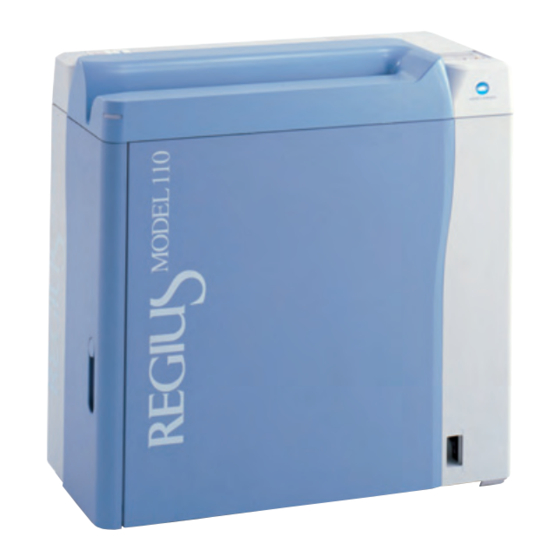
Chapter 2 Before the Repair Name of Parts Following are names of parts that is necessary to know when performing repair of the REGIUS MODEL 110. Exterior First front back side First front side Second front back side Second front side Name Function Air intake... - Page 23 Chapter 2 Before the Repair Vertical Positioning The front side (user's access direction) of the equipment can be changed by switching the operation panel position. Horizontal Positioning (Factory Default) Vertical Positioning Operation Operation panel panel Access Access direction direction Horizontal positioning: First front side will be the front. (This is the factory default.) Vertical positioning: Second front side will be the front.
-
Page 24: Structure
Chapter 2 Before the Repair Structure Following are the structure of the REGIUS MODEL 110. Name Function Insertion unit Constructed of slot to insert/eject the cassette, operation panel, barcode reader, shutter open and close mechanism. Exterior Unit to separate from outer environment, such as light shield, vibration blocker, etc. -
Page 25: Principal Specifications
Chapter 2 Before the Repair Principal Specifications 2.3.1 Equipment Specification Dimensions 740 (W) x 365 (D) x 747 (H) mm Weight Approximately 100 kg Floor height adjustment range Up to 12 mm bump at the position of the foot adjuster Noise level During operation: 55 dB or less During idle: 42 dB or less... -
Page 26: Read/Erase Of The Image
Chapter 2 Before the Repair 2.3.2 Read/Erase of the Image Processing Performance • Reading resolution Standard read mode: 175µm • High resolution read mode: 87.5µm Cassette feed load time 45 seconds or less (14 x 14 inches/standard read mode) • Time from the cassette is inserted until the cassette is ejected. - Page 27 Chapter 2 Before the Repair Optical Unit Laser scan unit Method Laser scan by polygon mirror Polygon face count 6 faces Laser wavelength 660 nm Laser intensity on the plate 35 mW or more surface Imaging beam diameter 100 µm or less (main and sub) Lens 2 group 2 lens Light condensing unit...
-
Page 28: Control Unit Performance
Chapter 2 Before the Repair 2.3.3 Control Unit Performance Major performance of the control unit is following. • Image data generation function A function to generate image data by laser scan • Image data compensation/ Moire elimination calculation function • Gain offset •... -
Page 29: Block Diagram
Block Diagram Insertion Unit Receiver Unit Subscan Unit Lock Motor (M2) LM Coil Unit (LM1) Operation Unit Mechanical Linkage Mechanical Linkage OPB (Operator's Panel Circuit Board) Lock HP Sensor (S9) Subscan HP Sensor (S14) LCD Panel Mechanical Linkage "operation" Lamp Receiver Encoder (S13) "erase"... - Page 30 2-10...
-
Page 31: Position Of Major Components
Chapter 2 Before the Repair Position of Major Components Position and function of the major components of each unit is described here. 2.5.1 Insertion Unit Name Function Reference on replacement method Insert slot detection Detects the insertion of the cassette. "5.3.7 Replacing the Insertion sensor 2 It is turned ON when the cassette... -
Page 32: Receiver Unit
Chapter 2 Before the Repair 2.5.2 Receiver unit Name Function Reference on replacement method Justifier guide Fix the cassette by moving inward "5.4.11 Replacing the Justifier and push the cassette against the Guide Unit Assembly (Page 5- justifier standard block. 60)"... -
Page 33: Transporter Unit
Chapter 2 Before the Repair Name Function Reference on replacement method Lock HP sensor Use to control the operation of "5.4.8 Replacing the Lock HP Lock Motor by the FPGA. Initial Sensor (Page 5-54)" position is ON. Lock/lock release Operate by Lock Motor, performing —... -
Page 34: Subscan Unit
Chapter 2 Before the Repair 2.5.4 Subscan Unit Name Function Reference on replacement method Tumbler (bottom) Fix the push plate unit to read "5.5.4 Replacing the Tumbler position with a spring. (Lower) (Page 5-77)" Wire Used on the position control "5.5.3 Replacing the Encoder/ encoder. -
Page 35: Optical Unit/Eraser Unit
Chapter 2 Before the Repair 2.5.5 Optical Unit/Eraser Unit Eraser unit Name Function Reference on replacement method • Erase lamp unit Halogen lamp is built-in, erasing Unit: Instruction manual the recording of the plate. • Halogen lamp only: "5.7.3 Replacing the Halogen Lamp (Page 5-88)"... -
Page 36: Detach Detection Unit
Chapter 2 Before the Repair 2.5.6 Detach Detection Unit Name Function Reference on replacement method Detach detection roller When the back plate or the plate "5.8.3 Replacing the Detach on the back plate is detached more Detection Roller (Page 5-93)" than certain amount from the push Top detach detection "5.8.1 Replacing the Detach... -
Page 37: Exterior
Chapter 2 Before the Repair 2.5.7 Exterior Name Function Reference on replacement method Interlock switch It turns ON when the second front "5.9.2 Replacing the Interlock door is open. Switch (Page 5-97)" All the power will be shut off, except for the electronic circuit board, when it is ON. - Page 38 Chapter 2 Before the Repair Name Function Reference on replacement method Interlock relay 1 A relay to cut power supply when "5.9.7 Replacing the the interlock is engaged. Transformer Unit Relay (Interlock Relay 1) (Page 5-105)" Analog power supply Supply the power supply (±5V, +24 "5.9.10 Replacing the Analog V) to the LMC (photomultiplier).
-
Page 39: Framework
Chapter 2 Before the Repair 2.5.8 Framework Name Function Reference on replacement method • Cleaning brush Clean the light condenser of the Brush only: "5.10.8 Replacing optical unit. the Brush (Cleaning Unit) (Page 5-131)" • Whole cleaner: "5.10.11 Replacing the Cleaning Unit (Page 5-135)"... -
Page 40: Operation
Chapter 2 Before the Repair Operation 2.6.1 Operation Transition Diagram Status Transition Diagram REGIUS MODEL 110 in in one of the following status. Power Supply Breaker ON Idling Press "operation" Switch Boot Shut down Press "operation" Press "operation" Switch for 3 Seconds Switch for 3 Seconds Sleep Mode Maintenance Mode... - Page 41 Chapter 2 Before the Repair Routine Mode Operation Transition Diagram Idling Press "operation" Intergradation Resulting Switch from Operation Automatic Intergradation Error Generated Initialization Process Close Door Finished Press "operation" Switch Open Door for 3 Seconds "READY" State Press "operation" Switch Press "erase"...
-
Page 42: Normal Operation (Image Read Action)
Chapter 2 Before the Repair 2.6.2 Normal Operation (Image Read Action) Action from the insertion to the eject of the cassette is described here. Use the service tool to confirm operation. See "Chapter 4 Confirming Operation Using Service Tool (Page 4-1)". - Page 43 Chapter 2 Before the Repair Justifier guide will move toward the justifier standard, pressing the cassette to the justifier standard block. Justifier motor will rotate, according to the cassette size from the barcode, moving the justifier guide to the justifier standard side. Justifier Guide Justifier Sensor Justifier HP Sensor...
- Page 44 Chapter 2 Before the Repair Lock/lock release mechanism will release the lock on the cassette. Lock motor will rotate operating the lock/rock release mechanism, releasing the lock on the cassette. Lock/Lock Release Mechanism Lock HP Sensor The push plate unit that absorbed the back plate will move to the read position.
- Page 45 Chapter 2 Before the Repair Push plate unit will move to the press down position and press the back plate to the front plate. Transporter motor will rotate to move the push plate unit to the push down position. Lock/lock release mechanism will lock the cassette.
- Page 46 Chapter 2 Before the Repair Receiver will rise to the home position. Receiver motor will rotate and receiver will rise to the home position. Receiver HP Sensor Sensor at the insertion slot will detect ejection of the cassette. Ejecting of cassette is completed when the following sensors turns OFF.
-
Page 47: Initialization Action
Chapter 2 Before the Repair 2.6.3 Initialization Action Initialization action will be performed according to the timing of each status transition. Description of initialization action per initialization operation timing Initialization timing Initialization action After power on " Initialization of the FPGA" "... - Page 48 Chapter 2 Before the Repair Initialization and operation check sequence of the mechanical unit Start With Cassette Check Cassette Detection Receiver at Sensor HP Position? Jam Evacuation Without Cassette Action Move Down Shutter Close? Wait for Door Receiver Minutely Open Move Receiver Initialization of Wait for Door...
- Page 49 Chapter 2 Before the Repair Initialization of the Mechanical Unit • Check if there is cassette inside the equipment and close the shutter. • Move the unit to the initial position. • Shutter: Closed • Receiver: Receiver home position • Justifier guide: Justifier home position •...
-
Page 50: Erase Action
Chapter 2 Before the Repair 2.6.4 Erase Action Erase mode is composed of 2 modes. It will go into the erase mode (quick) by pressing the erase switch for more than 3 seconds when the equipment is in READY status. It will transit to the erase mode (slow) by pressing the erase switch in the erase mode (quick) status. -
Page 51: Handling The Cassette
Chapter 2 Before the Repair Handling the Cassette Please be familiar with the following cautions when handling the REGIUS cassettes (RC-110 series). Maintaining the image quality • Be cautious no scratch or foreign object goes on the read surface of the plate. •... -
Page 52: Tools, Measuring Devices, Jigs, Etc., Necessary For Service
Chapter 2 Before the Repair Tools, Measuring Devices, Jigs, Etc., Necessary for Service Following tools, measuring devices, and jigs are necessary when performing service on the REGIUS MODEL 110. Jigs/tools Note Phillips driver Standard tools Slotted tip driver Allen wrench Wrench Wire cutter Tray... - Page 53 Chapter 2 Before the Repair Supplied Products Jigs/tools Note Alcohol Used to clean the cassette absorption plate. Grease (for LM guide) AFC grease by THK Grease (all parts except LM guide) Plusguard No 2 by Kyodo Yushi Wiring band Snap ties 2-33...
- Page 55 Chapter Troubleshooting Chapter 3 How to respond to a trouble on the equipment is described here. Workflow ............3-2 Description of the Error Codes and How to Respond.............3-5 Response to the Problems Not Displaying Error ..............3-32 How to Respond on Image Defect ....3-38...
-
Page 56: Chapter 3 Troubleshooting
Chapter 3 Troubleshooting Workflow Following describes the flow of response when there is a problem with the equipment. Type of trouble Flow of response Trouble that displays an error message 1. Check if there is a cassette inside the equipment and on the message display window restart the equipment. -
Page 57: Restore Operation
Chapter 3 Troubleshooting 3.1.1 Restore Operation When the error occurs, confirm if the error recur after restarting the equipment. Hot to restart is described here. Open the second front door. Eject the cassette if it is possible to eject the cassette. - Page 58 Chapter 3 Troubleshooting Eject the cassette if the cassette is still in the equipment. When the push plate is not at the read position 1. See " Removal Procedures (Page 5-6)" of the "5.2.3 Removing/Installing the Exterior Panel and Insertion Unit", and remove the first font back panel.
-
Page 59: Description Of The Error Codes And How To Respond
Chapter 3 Troubleshooting Description of the Error Codes and How to Respond 3.2.1 06000 ~ 06037: Justifier Motor Errors • Error codes S column: Errors at the read operation/calibration. • Error codes E column: Errors during erase operation. • Error codes I column: Errors during initialization. Error code Description of the error Response... - Page 60 Chapter 3 Troubleshooting Error code Description of the error Response (References to replacement methods are listed at the end of the table.) 06008 06023 06038 Justifier HP sensor error Confirm following and replace the faulty (when moving to HP 3) parts.
-
Page 61: 06050 ~ 06090: Receiver Motor Errors
Chapter 3 Troubleshooting 3.2.2 06050 ~ 06090: Receiver Motor Errors • Error codes S column: Errors at the read operation/calibration. • Error codes E column: Errors during erase operation. • Error codes I column: Errors during initialization. Error code Description of the error Response (References to replacement methods are listed at the end of the table.) - Page 62 Chapter 3 Troubleshooting Error code Description of the error Response (References to replacement methods are listed at the end of the table.) 06058 06073 06088 Receiver motor control error Confirm following and replace the faulty parts. (when moving to HP 2) •...
-
Page 63: 06100 ~ 06143: Transporter Motor Errors
Chapter 3 Troubleshooting 3.2.3 06100 ~ 06143: Transporter Motor Errors • Error codes S column: Errors at the read operation/calibration. • Error codes E column: Errors during erase operation. • Error codes I column: Errors during initialization. Error code Description of the error Response (References to replacement methods are listed at the end of the table.) - Page 64 Chapter 3 Troubleshooting Error code Description of the error Response (References to replacement methods are listed at the end of the table.) 06103 06118 06133 Transporter HP sensor error 1. Confirm that there are no foreign (when moving to HP) objects between the push plate and Transporter HP sensor did not the frame, and remove if there are any.
- Page 65 Chapter 3 Troubleshooting Error code Description of the error Response (References to replacement methods are listed at the end of the table.) 06106 06121 06136 Transporter motor control 1. Confirm the ground. (It may cause error (when moving to press noise) down position) 2.
- Page 66 Chapter 3 Troubleshooting Error code Description of the error Response (References to replacement methods are listed at the end of the table.) 06109 06124 06139 Transporter read sensor error 1. Confirm that there are no foreign (when moving to press down objects between the push plate and position 2) the frame, and remove if there are any.
-
Page 67: 06150 ~ 06182: Subscan Motor Errors
Chapter 3 Troubleshooting Error code Description of the error Response (References to replacement methods are listed at the end of the table.) 06113 06128 06143 Transporter motor control 1. Confirm the ground. (It may cause error (when moving to HP 2) noise) There was a trouble with the 2. - Page 68 Chapter 3 Troubleshooting Error code Description of the error Response 06151 06166 06181 Subscan motor control error 1. Confirm that the fixing shaft of the (when moving to mechanical simple fixing lock is not lowered. 2. Confirm there are no foreign objects There was a trouble with the on the magnet shaft of the subscan motor control when the subscan...
-
Page 69: 06200 ~ 06231: Insertion Shuttermotor Errors
Chapter 3 Troubleshooting 3.2.5 06200 ~ 06231: Insertion ShutterMotor Errors • Error codes S column: Errors at the read operation/calibration. • Error codes E column: Errors during erase operation. • Error codes I column: Errors during initialization. Error code Description of the error Response (References to replacement methods are listed at the end of the table.) -
Page 70: 06250 ~ 06282: Lock Release Motor Errors
Chapter 3 Troubleshooting 3.2.6 06250 ~ 06282: Lock Release Motor Errors • Error codes S column: Errors at the read operation/calibration. • Error codes E column: Errors during erase operation. • Error codes I column: Errors during initialization. Error code Description of the error Response (References to replacement methods are... -
Page 71: 06300 ~ 06333: Justifier Sensor Errors
Chapter 3 Troubleshooting 3.2.7 06300 ~ 06333: Justifier Sensor Errors • Error codes S column: Errors at the read operation/calibration. • Error codes E column: Errors during erase operation. • Error codes I column: Errors during initialization. Error code Description of the error Response (References to replacement methods are listed at the end of the table.) - Page 72 Chapter 3 Troubleshooting Error code Description of the error Response (References to replacement methods are listed at the end of the table.) 06302 Cassette during the startup 1. Confirm for foreign object inside the (justifier sensor) equipment, and remove it if there is Justifier sensor or justifier any.
-
Page 73: 06350 ~ 06385: Receiver Sensor Errors
Chapter 3 Troubleshooting 3.2.8 06350 ~ 06385: Receiver Sensor Errors • Error codes S column: Errors at the read operation/calibration. • Error codes E column: Errors during erase operation. • Error codes I column: Errors during initialization. Error code Description of the error Response (References to replacement methods are listed at the end of the table.) -
Page 74: 06400 ~ 06432: Back Plate Detection Sensor Errors
Chapter 3 Troubleshooting 3.2.9 06400 ~ 06432: Back Plate Detection Sensor Errors • Error codes S column: Errors at the read operation/calibration. • Error codes E column: Errors during erase operation. • Error codes I column: Errors during initialization. Error code Description of the error Response (References to replacement methods are... -
Page 75: 06450 ~ 06483: Detach Detection Sensor Errors
Chapter 3 Troubleshooting 3.2.10 06450 ~ 06483: Detach Detection Sensor Errors • Error codes S column: Errors at the read operation/calibration. • Error codes E column: Errors during erase operation. • Error codes I column: Errors during initialization. Error code Description of the error Response (References to replacement methods are... -
Page 76: 06500 ~ 06533: Insertion Slot Detection Sensor Errors
Chapter 3 Troubleshooting 3.2.11 06500 ~ 06534: Insertion Slot Detection Sensor Errors • Error codes S column: Errors at the read operation/calibration. • Error codes E column: Errors during erase operation. • Error codes I column: Errors during initialization. Error code Description of the error Response (References to replacement methods are... - Page 77 Chapter 3 Troubleshooting Error code Description of the error Response (References to replacement methods are listed at the end of the table.) 06503 06518 06533 Cassette back plate drop When the back plate is off detection 1. Check the cassette. Back plate drop detection sensor was OFF (drop detected) after •...
-
Page 78: 06550 : Optical Unit/Eraser Unit Errors
Chapter 3 Troubleshooting 3.2.12 06550 : Optical Unit/Eraser Unit Errors • Error codes S column: Errors at the read operation/calibration. • Error codes E column: Errors during erase operation. • Error codes I column: Errors during initialization. Error code Description of the error Response (References to replacement methods are listed at the end of the table.) -
Page 79: 06650 ~ 06683: Fpga Errors
Chapter 3 Troubleshooting 3.2.14 06650 ~ 06683: FPGA Errors • Error codes S column: Errors at the read operation/calibration. • Error codes E column: Errors during erase operation. • Error codes I column: Errors during initialization. Error code Description of the error Response (References to replacement methods are listed at the end of the table.) -
Page 80: 14000 ~ 15000: Signal Process Errors
Chapter 3 Troubleshooting 3.2.15 14000 ~ 15000: Signal Process Errors Error Description of the error Response code (References to replacement methods are listed at the end of the table.) 14000 Signal process error Confirm the operation of the LMC with standard current read if it recur. -
Page 81: 23000 ~ 23900: Program Errors
Chapter 3 Troubleshooting 3.2.16 23000 ~ 23900: Program Errors Error Description of the error Response code (References to replacement methods are listed at the end of the table.) 23000 Program error Confirm the following when it recur. − Main control 1. -
Page 82: 26000 ~ 26900: Operation Errors
Chapter 3 Troubleshooting Error Description of the error Response code (References to replacement methods are listed at the end of the table.) 25000 Network error Confirm in following order: − Non-timeout 1. Confirm if the console in communication is operating Network control program has normally. - Page 83 Chapter 3 Troubleshooting Error Description of the error Response code (References to replacement methods are listed at the end of the table.) 26300 Operation error Operation will continue without any problems. Perform the operation on the console again after the −...
-
Page 84: Confirm The H-Sync Signal
Chapter 3 Troubleshooting 3.2.19 Confirm the H-sync Signal (To be stated) 3-30... -
Page 85: Confirm The Lmc Operation
Chapter 3 Troubleshooting 3.2.20 Confirm the LMC Operation (To be stated) 3-31... -
Page 86: Response To The Problems Not Displaying Error
Chapter 3 Troubleshooting Response to the Problems Not Displaying Error The problems originated from electric regulation/communication are described below. • Network Related • Power ON/OFF Related • Signal processing related (control/error) 3.3.1 Network Related Phenomenon: "READY" is displayed, but the image is not transferred when it is registered and read is performed. - Page 87 Chapter 3 Troubleshooting Phenomenon Occurring by Setup Problem Following phenomenon will occur when there is incorrect setup (like same IP address) in the REGIUS MODEL 110, REGIUS console, and JM. Restart after setting up so the IP addresses and host names do not duplicate. Setup condition Phenomenon •...
-
Page 88: Power On/Off Related
Chapter 3 Troubleshooting Setup condition Phenomenon • There are REGIUS console and JM with same When you set the IP address and host name of IP address and host name. the REGIUS console to the one used in the JM, REGIUS console will not startup. - Page 89 Chapter 3 Troubleshooting Analysis Procedure of Power Supply Problems (Cannot Turn ON the Power Supply) When the power does not go ON by pressing the "operation" switch, confirm from top of the next table, and respond accordingly. (See next page for the position of each parts.) Confirm Possible fault location for no output*...
- Page 90 Chapter 3 Troubleshooting First Front Side JP25 PCN2 Noise Filter Interlock Switch AC Inlet Standby Power JJ10 Digital Power Power Supply Supply Supply Breaker Transformer First Front Side Back MCN7 MCN2 3-36...
-
Page 91: Signal Processing Related
Chapter 3 Troubleshooting 3.3.3 Signal Processing Related Troubles caused by the signal processing is described here. Phenomenon: Image transfer is very slow (cycle timeover even for single read) Cause Response There might be a 10BASE network hub Confirm the network hubs and cables. or cable used in the network system. -
Page 92: How To Respond On Image Defect
Chapter 3 Troubleshooting How to Respond on Image Defect How to respond on image defect is described here. 3.4.1 Flow of Response Flow of response to image defect is described hereafter. Item Description Confirm the phenomenon Confirm the phenomenon of the image defect, and search if it is in table "... - Page 93 Chapter 3 Troubleshooting Phenomenon List Find the corresponding phenomenon from the list and respond according to the reference. Phenomenon Reference Image is dark or black in general (still with structure of the object) page 3-40 Image is bright or white in general (still with structure of the object) page 3-40 Horizontal streak in part of the image page 3-41...
-
Page 94: Image Is Dark Or Black In General (Still With Structure Of The Object)
Chapter 3 Troubleshooting 3.4.2 Image is Dark or Black in General (Still With Structure of the Object) Cause Response Output density in the G process See the Image Process Adjustment Manual and set parameter is set high in general. the Density H/L in the G process parameter lower. X-ray dosage is too much (in case of fix Confirm the exposure condition if the X-ray dosage is the process or unprocessed image). -
Page 95: Horizontal Streak In Part Of The Image
Chapter 3 Troubleshooting 3.4.4 Horizontal Streak in Part of the Image Always perform the image size adjustment, the image position adjustment, the unevenness calibration, and the sensitivity calibration after replacing the optical unit. Important Phenomenon: Streak appears in part of the image Cause External force was applied during the read. -
Page 96: Horizontal Streak All Over The Image
Chapter 3 Troubleshooting Phenomenon: 1 to few lines of horizontal line looking digital Cause Response Connection failure Confirm the connection of the LMC connectors (CN8, J1, CN301, CN302, CN303, and CN304). H-sync signal detection problem. Confirm the H-sync signal using the oscilloscope and replace the optical unit if there is a fault. -
Page 97: Vertical Streak
Chapter 3 Troubleshooting Phenomenon: Horizontal streaks of 20 ~ 60 steps in 4 ~ 5 line cycle all over the image Cause Response Under effect of the radiofrequency Confirm if the horizontal streaks disappear by turning treatment equipment. OFF the radiofrequency treatment equipment or point the antenna away from the equipment. -
Page 98: Quasi-Contour In The Image
Chapter 3 Troubleshooting Phenomenon: Faint black steak Cause Response When there is no streak by reading Redo the unevenness calibration. without any correction Correction could of been made with a dust on the CY2 mirror. White steak is at the same position by Replace the optical unit. -
Page 99: Image Size Is Different (Horizontally)
Chapter 3 Troubleshooting 3.4.10 Image Size is Different (Horizontally) Cause Response Image size setup value was replaced. Confirm and correct the image size setup value. 3.4.11 Top and Bottom of the Image is Trimmed Cause Response Aperture of the X-ray is not appropriate. Confirm the exposure field. -
Page 100: S Value Fluctuation
Chapter 3 Troubleshooting 3.4.15 S Value Fluctuation Phenomenon Response Fluctuation within Fluctuate when the 87.5µm and 175 µm will not have identical S value due same equipment sampling pitch is to the difference in the read pitch, resulting as different difference in the luminance. -
Page 101: Sandy Image
Chapter 3 Troubleshooting 3.4.19 Sandy Image Cause Response Not enough dosage from X-ray tube. Confirm the dosage of the X-ray tube. Perform the mR measurement and confirm if there is any X-ray. Wrong exposure conditions Confirm the exposure conditions referring to the recommended value in the medical notebook. -
Page 102: All Processed Images Are Generally Low In Contrast
Chapter 3 Troubleshooting 3.4.26 All Processed Images are Generally Low in Contrast Cause Response • Output density in the process parameter Reset the rotate/shift parameter output density H is set low in contrast in general. higher. • Reset the rotate/shift parameter output density L lower. -
Page 103: Chapter 4 Confirming Operation Using Service Tool
Chapter Confirming Operation Chapter 4 Using Service Tool Methods to confirm the operation of REGIUS MODEL 110 is described here. Before Confirming the Operation .......4-2 Display [Unit Test] Screen........4-3 Confirming Operation for Each Unit ....4-6 Confirming by Step Operation......4-8 Confirming the Status of the Sensors ....4-17... -
Page 104: Before Confirming The Operation
Chapter 4 Confirming Operation Using Service Tool Before Confirming the Operation 4.1.1 Outline of Confirming the Operation To confirm the operation of each unit of the REGIUS MODEL 110 or confirm the status of the sensors, operate the [Unit Test] screen in the service tool (only for the REGIUS MODEL 110) on the REGIUS console. -
Page 105: Display [Unit Test] Screen
[Service Tool] screen (console) is displayed. Click the [Reader] button. [Service Tool] screen (reader) is displayed. Click the [Unit Test] button in the [REGIUS 110]. [Unit Test] screen is displayed. (REGIUS) service See the Installation/Service Manual for the REGIUS console on how to display the screen and [Service Tool] screen (console/reader). -
Page 106: Function Outline Of The [Unit Test] Screen
Chapter 4 Confirming Operation Using Service Tool 4.2.2 Function Outline of the [Unit Test] Screen [Unit Test] is composed of 8 screens, and panels are switched using the tab. Contents of each panels are as following: Panel name Description Indicator Stand-alone operation for following units can be confirmed. - Page 107 Chapter 4 Confirming Operation Using Service Tool Panel name Description Adjustment Following adjustment can be performed. • Amount of Justification (Receiver Motor) • Pressing Amount (Transporter Motor) • Monitoring Confirmation of the operation by step operation of the mechanical can be performed.
-
Page 108: Confirming Operation For Each Unit
Chapter 4 Confirming Operation Using Service Tool Confirming Operation for Each Unit Procedure to confirm the operation is explained here using stand-alone action of the receiver motor. Do not use the cassette for confirming operation for each unit (except for "Adjustment" and "Monitoring"... - Page 109 Chapter 4 Confirming Operation Using Service Tool Initialization of Justifier Motor The following operation is necessary only when performing an initialization of the justifier motor. It will stop with the message, [Uploading...] displayed when the [Initialization] button for justifier motor is clicked.
-
Page 110: Confirming By Step Operation
Chapter 4 Confirming Operation Using Service Tool Confirming by Step Operation Procedure to confirm the operation by step operation is described here. You can not terminate the process half-way between the steps. Perform all the way to the last step. To stop half-way between the steps, perform following steps to force quit the process. Important 1. - Page 111 Chapter 4 Confirming Operation Using Service Tool Click the [Initialization] button. Initialization action will be performed, and [Next] button will be enabled one it is completed. Click the [ ] button. Next Step operation is performed. When using the cassette Click the [Next] button after setting the cassette in the insertion slot.
- Page 112 Chapter 4 Confirming Operation Using Service Tool Sequence SeqID Operation type* Move the push plate unit to the read position Slightly lower the receiver Read Erase Move the push plate unit to the press down position Lock Move the push plate unit to the passing point of the home position Move the push plate unit to the home position &...
- Page 113 Chapter 4 Confirming Operation Using Service Tool SeqID=51: Read barcode SeqID=52: Open shutter & wait cassette drop SeqID=53: Move receiver to first falling position SeqID=54: Fix cassette with justifier guide at first falling position 4-11...
- Page 114 Chapter 4 Confirming Operation Using Service Tool SeqID=55: Slightly release the fixing of cassette by the justifier guide Depending on the cassette type, Justifier S1 = ON and Justifier S2 = OFF, but both are correct as a sensor status. SeqID=56: Move the receiver to second falling position SeqID=57: Fix cassette with justifier guide at second falling position SeqID=58: Move the push plate unit to the press down position &...
- Page 115 Chapter 4 Confirming Operation Using Service Tool SeqID=59: Release lock SeqID=60: Move push plate to read position SeqID=61: Slightly lower the receiver SeqID=62: Read 4-13...
- Page 116 Chapter 4 Confirming Operation Using Service Tool SeqID=63: Erase SeqID=64: Move push plate unit to pressing position SeqID=65: Lock SeqID=66: Move push plate unit to the passing point of the home position 4-14...
- Page 117 Chapter 4 Confirming Operation Using Service Tool SeqID=67: Move push plate unit to home position & open shutter SeqID=68: Slightly release the fixing of the cassette with justifier guide Depending on the cassette type, it might show Justifier S1 = ON and Justifier S2 = OFF, but both are correct as a sensor status.
- Page 118 Chapter 4 Confirming Operation Using Service Tool SeqID=71: Move the receiver to home position Cassette Insertion S2 stays OFF when the cassette is 15 x 30 cm. SeqID=72: Detection of cassette ejection SeqID=73: Close shutter (finished) 4-16...
-
Page 119: Confirming The Status Of The Sensors
Chapter 4 Confirming Operation Using Service Tool Confirming the Status of the Sensors Confirmation procedure of the sensor status is described here. Click the [Monitoring] tab in the [Unit Test] screen. [Monitoring] panel is displayed. Click the [Start] button. Monitoring of the sensor status of the REGIUS MODEL 110 will start. -
Page 121: Chapter 5 Disassembly And Assembly
Chapter Disassembly and Chapter 5 Assembly This chapter describes the instructions on how to disassemble/ assemble the equipment. Before Disassembly ...........5-2 Basic Works ............5-3 Replacing the Parts on the Insertion Unit ..5-19 Replacing the Parts on the Receiver unit..5-40 Replacing the Parts on the Subscan Unit ..5-65 Replacing the Parts on the Optical Unit ...5-78 Replacing the Parts on the Eraser Unit....5-83 Replacing the Parts on the Detach Detection... -
Page 122: Before Disassembly
Chapter 5 Disassembly and Assembly Before Disassembly 5.1.1 Precautions during Disassembly/Assembly Be sure to turn off the power supply circuit breaker and unplug the power cable from the equipment whenever you disassemble/assemble the equipment. Failure to do so may lead to Caution malfunction, causing your fingers to be wedged between the sliding or rotating parts inside the equipment. -
Page 123: Basic Works
Chapter 5 Disassembly and Assembly Basic Works This section describes the works including the basic instructions on how to remove/install the exterior panels that are required in disassembling/assembling the equipment. 5.2.1 Power OFF/ON This section describes the instructions on how to turn the power off/on on the equipment. Power OFF Turn the power supply circuit breaker OFF and unplug the power cable and the Ethernet cable. - Page 124 Chapter 5 Disassembly and Assembly Power ON Connect the Ethernet cable and power cable and turn ON the power. Connect the Ethernet cable to the equipment. Connect the power cable to the equipment and power outlet. Second Front Back Side Turn on the power supply circuit breaker.
-
Page 125: Moving The Equipment
Chapter 5 Disassembly and Assembly 5.2.2 Moving the Equipment Move the equipment to a place available for servicing if it is hard to operate service at the installation site. Moving to the Maintenance Space Move the optical unit to the second front side and fix it using the simple fixing lock. -
Page 126: Removing/Installing The Exterior Panel And Insertion Unit
Chapter 5 Disassembly and Assembly 5.2.3 Removing/Installing the Exterior Panel and Insertion Unit This section describes the instructions on how to remove and install the exterior panel and insertion unit. Be sure to turn off the power supply circuit breaker and unplug the power cable from the equipment whenever you disassemble/assemble the equipment. - Page 127 Chapter 5 Disassembly and Assembly Removing the First Front Panel Remove the first front panel. • 6 screws (M4 x 8) Remove the panel with both hands, holding on the bottom and pulling away from the equipment. First Front Side Removing the Insertion Unit Remove the circuit board cover.
- Page 128 Chapter 5 Disassembly and Assembly Remove the insertion unit. Place the removed insertion unit upside down to prevent any damage inside, on a stable location. Remove the unit carefully so the cables disconnected in Step 5 do not get caught. Caution Now, you have finished with the procedure to remove the exterior panels and the insertion unit.
- Page 129 Chapter 5 Disassembly and Assembly Install the circuit board cover. • 3 screws (M3 x 6) First Front Back Side Installing the First Front Panel Install the first front panel. • 6 screws (M4 x 8) Hold the bottom part of the first front panel with both hands, and install it by inserting the top part of panel into the panel.
-
Page 130: Removing/Installing The Second Front Door
Chapter 5 Disassembly and Assembly 5.2.4 Removing/Installing the Second Front Door This section describes the instructions on how to remove and install the second front door. Be sure to turn off the power supply circuit breaker and unplug the power cable from the equipment whenever you disassemble/assemble the equipment. -
Page 131: Removing/Installing The Optical Unit
Chapter 5 Disassembly and Assembly 5.2.5 Removing/Installing the Optical Unit This section describes the instructions on how to remove and install the optical unit. • Be sure to turn off the power supply circuit breaker and unplug the power cable from the equipment whenever you disassemble/assemble the equipment. - Page 132 Chapter 5 Disassembly and Assembly Fix the unit using a simple fixing lock. When the optical unit moves all the way toward the front, fixing shaft will Note automatically lower to lock. Second Front Side Remove the setscrews on the second front side of the optical unit.
- Page 133 Chapter 5 Disassembly and Assembly Remove the cables connected to the optical unit. • • CN1 (ACN1: cable) • CN2 (ACN2: cable) • CN4 (ACN4: cable) Second Front • CN5 (ACN5: cable) Back Side • CN9 (ACN9: cable) • • CN2 (LMCN2: cable) This connector may have been fixed very tightly.
- Page 134 Chapter 5 Disassembly and Assembly Remove the optical unit, holding the knob on top of the optical unit with the bottom surface. Knob Place the removed optical unit in a level and stable place. Second Front Back Side If you are going to lay it down, turn up the light condensing unit and cover it with a vinyl sheet in order Light Condensing Unit to screen out dust on it.
- Page 135 Chapter 5 Disassembly and Assembly Connect the cables to the circuit board on the optical unit. • • CN1 (ACN1: cable) • CN2 (ACN2: cable) Second Front • CN4 (ACN4: cable) Back Side • CN5 (ACN5: cable) • CN9 (ACN9: cable) •...
- Page 136 Chapter 5 Disassembly and Assembly Release the simple fixing lock and move the optical unit to the second front side. In the second front side, fix the optical unit using a simple fixing lock. Fully tighten the setscrews on the second front side.
-
Page 137: Moving The Push Plate Unit
Chapter 5 Disassembly and Assembly 5.2.6 Moving the Push Plate Unit This section describes the instructions on how to move the push plate unit with the power off. • First, move the optical unit to the second front back side, then move the push plate unit. •... -
Page 138: Binding The Grounding Strap
Chapter 5 Disassembly and Assembly 5.2.7 Binding the Grounding Strap You must bind the grounding strap when accessing the circuit board in order to prevent the circuit board being damaged by static discharge. Caution Bind the grounding strap around your wrist, then have the other clip nip the metallic portion of the main unit that is surely grounded. -
Page 139: Replacing The Parts On The Insertion Unit
Chapter 5 Disassembly and Assembly Replacing the Parts on the Insertion Unit 5.3.1 Replacing the Operation Unit (Operation Panel) This section describes the instructions on how to replace the operation unit. Following are the procedures available for the unit with the horizontal positioning, though the same procedures can be used for the unit with the vertical positioning. -
Page 140: Changing The Mounting Location Of The Operation Unit
Chapter 5 Disassembly and Assembly 5.3.2 Changing the Mounting Location of the Operation Unit This section describes the instructions on how to change the mounting location of the operation unit. Following are the procedures taking example for the case that the horizontal positioning will be changed to the vertical positioning, though the same procedures can be used for the unit with the vertical positioning. - Page 141 Chapter 5 Disassembly and Assembly Remove the operation unit. • 4 tapping screws (M4 x 10) Place the operation unit at the position where the dummy operation unit was placed. • 4 tapping screws (M4 x 10) Follow the figure to wire the cables to the operation unit.
-
Page 142: Replacing The Eraser Cooling Fan
Chapter 5 Disassembly and Assembly 5.3.3 Replacing the Eraser Cooling Fan This section describes the instructions on how to replace the eraser cooling fan. Be sure to turn off the power supply circuit breaker and unplug the power cable from the equipment whenever you disassemble/assemble the equipment. -
Page 143: Replacing The Indicator
Chapter 5 Disassembly and Assembly 5.3.4 Replacing the Indicator This section describes the instructions on how to replace the indicator. Be sure to turn off the power supply circuit breaker and unplug the power cable from the equipment whenever you disassemble/assemble the equipment. Caution Work outline Listed below are the number of people and the rough standard of work hours required for performing the... -
Page 144: Replacing The Barcode Reader
Chapter 5 Disassembly and Assembly Install the insertion indicator unit assembly. • 1 tapping screw (M4 x 10) Move the insertion indicator in the direction of the arrow shown in the figure to fix it. " Installation Procedures (Page 5-8)" "5.2.3 Removing/Installing the Exterior Panel and Insertion Unit"... - Page 145 Chapter 5 Disassembly and Assembly Remove the connector (JJ38). When removing the connector, hold a notch JJ38 on the connector without pulling a cable. Caution Giving a strong pull to the cable may cause it to be broken. Remove the barcode reader. •...
-
Page 146: Replacing The Back Plate Drop Detection Sensor
Chapter 5 Disassembly and Assembly 5.3.6 Replacing the Back Plate Drop Detection Sensor This section describes the instructions on how to replace the back plate drop detection sensor. Be sure to turn off the power supply circuit breaker and unplug the power cable from the equipment whenever you disassemble/assemble the equipment. -
Page 147: Replacing The Insertion Slot Detection Sensors (Llb)
Chapter 5 Disassembly and Assembly 5.3.7 Replacing the Insertion Slot Detection Sensors (LLB) This section describes the instructions on how to replace the insertion slot detection sensors (LLB). Be sure to turn off the power supply circuit breaker and unplug the power cable from the equipment whenever you disassemble/assemble the equipment. -
Page 148: Replacing The Insertion Slot Detection Sensors (Lpb)
Chapter 5 Disassembly and Assembly Install the light shield cover that was removed in Step • 1 tapping screw (M4 x 10) • 1 screw (M4 x 8) Attach the sponge to the right side of the light shield cover, and wrap the cable with it. "... - Page 149 Chapter 5 Disassembly and Assembly Remove the shutter unit assembly. • 5 tapping screws (M4 x 10) Remove the sensor cover. • 2 screws (M4 x 8) Remove the insertion slot detection sensors Sensor 2 (LPB1) (LPB). • Insertion slot detection sensor 1: 1 screw (M3 x 6) •...
- Page 150 Chapter 5 Disassembly and Assembly Install the shutter unit assembly that was removed in Step • 5 tapping screws (M4 x 10) Press it in a direction of the arrow shown in the figure to fix it. Use a 0.2 mm-spacer (film) to check the clearance between the lock cam and the stopper block.
-
Page 151: Replacing The Shutter Open Detection Sensor
Chapter 5 Disassembly and Assembly 5.3.9 Replacing the Shutter Open Detection Sensor This section describes the instructions on how to replace the shutter open detection sensor. Be sure to turn off the power supply circuit breaker and unplug the power cable from the equipment whenever you disassemble/assemble the equipment. - Page 152 Chapter 5 Disassembly and Assembly Remove the bracket from the shutter open detection sensor. • 1 screw (M4 x 8) Remove the shutter open detection sensor. Install the new shutter open detection sensor on the bracket. Install the bracket that was removed in Step •...
-
Page 153: Replacing The Shutter Close Detection Sensor
Chapter 5 Disassembly and Assembly Connect the cables that were unplugged in Step Grounding Cable to the shutter unit assembly. • Connector (JP20): shutter motor JP36 • Connector (JP35): shutter close detection sensor • Connector (JP36): shutter open detection sensor •... - Page 154 Chapter 5 Disassembly and Assembly Remove the bracket from the shutter close detection sensor. • 1 screw (M4 x 8) Remove the shutter close detection sensor. Install the new shutter close detection sensor on the bracket. Install the bracket that was removed in Step •...
-
Page 155: Replacing The Shutter Motor
Chapter 5 Disassembly and Assembly 5.3.11 Replacing the Shutter Motor This section describes the instructions on how to replace the shutter motor. Be sure to turn off the power supply circuit breaker and unplug the power cable from the equipment whenever you disassemble/assemble the equipment. Caution Work outline Listed below are the number of people and the rough standard of work hours required for performing the... -
Page 156: Replacing The Shutter Unit
Chapter 5 Disassembly and Assembly 5.3.12 Replacing the Shutter Unit This section describes the instructions on how to replace the shutter unit. Be sure to turn off the power supply circuit breaker and unplug the power cable from the equipment whenever you disassemble/assemble the equipment. Caution Work outline Listed below are the number of people and the rough standard of work hours required for performing the... - Page 157 Chapter 5 Disassembly and Assembly Replace the parts. Removing the Shutter Motor and Shutter Sensor Unit Assembly Removing the Shutter Motor and Shutter Plate unit Assembly and Cam Unit Assembly 5-37...
- Page 158 Chapter 5 Disassembly and Assembly Removing the Lock Unit Assembly Assembly Figure Watch for orientation Install the shutter unit assembly that was removed in Step • 5 tapping screws (M4 x 10) Press it in the direction of the arrow shown in the figure to fix it.
- Page 159 Chapter 5 Disassembly and Assembly Connect the cables that were unplugged in Step Grounding Cable to the shutter unit assembly. • Connector (JP20): shutter motor JP36 • Connector (JP36): shutter close detection sensor • Connector (JP35): shutter open detection sensor •...
-
Page 160: Replacing The Parts On The Receiver Unit
Chapter 5 Disassembly and Assembly Replacing the Parts on the Receiver unit 5.4.1 Replacing the Justifier HP Sensor This section describes the instructions on how to replace the justifier HP sensor. Be sure to turn off the power supply circuit breaker and unplug the power cable from the equipment whenever you disassemble/assemble the equipment. -
Page 161: Replacing The Justifier Sensor
Chapter 5 Disassembly and Assembly 5.4.2 Replacing the Justifier Sensor This section describes the instructions on how to replace the justifier sensor. Be sure to turn off the power supply circuit breaker and unplug the power cable from the equipment whenever you disassemble/assemble the equipment. Caution Work outline Listed below are the number of people and the rough standard of work hours required for performing the... -
Page 162: Replacing The Justifier Motor
Chapter 5 Disassembly and Assembly 5.4.3 Replacing the Justifier Motor This section describes the instructions on how to replace the justifier motor. Be sure to turn off the power supply circuit breaker and unplug the power cable from the equipment whenever you disassemble/assemble the equipment. Caution Work outline Listed below are the number of people and the rough standard of work hours required for performing the... - Page 163 Chapter 5 Disassembly and Assembly Remove the justifier motor. • 4 screws (M4 x 12) Remove the gear. • 2 setscrews Install the gear on the new justifier motor. • 2 setscrews Fix the gear, fitting the edge surfaces of it and the motor shaft.
-
Page 164: Replacing The Justifier Standard Sensor
Chapter 5 Disassembly and Assembly 5.4.4 Replacing the Justifier Standard Sensor This section describes the instructions on how to replace the justifier standard sensor. Be sure to turn off the power supply circuit breaker and unplug the power cable from the equipment whenever you disassemble/assemble the equipment. - Page 165 Chapter 5 Disassembly and Assembly Unplug the cable. • Connector (JP44) JP44 When removing the connector, hold a notch on the connector without pulling a cable. Caution Giving a strong pull to the cable may cause it to be broken. Remove the justifier detection mount board 2.
-
Page 166: Replacing The Receiver Sensor
Chapter 5 Disassembly and Assembly 5.4.5 Replacing the Receiver Sensor This section describes the instructions on how to replace the justifier receiver sensor. Be sure to turn off the power supply circuit breaker and unplug the power cable from the equipment whenever you disassemble/assemble the equipment. - Page 167 Chapter 5 Disassembly and Assembly Remove the receiver detection mount board. • 1 screw (M3 x 6) Unplug the cable from the receiver sensor. • Connector (JP42) When removing the connector, hold a notch on the connector without pulling a cable. Caution Giving a strong pull to the cable may cause it to be broken.
-
Page 168: Replacing The Receiver Hp Sensor
Chapter 5 Disassembly and Assembly 5.4.6 Replacing the Receiver HP Sensor This section describes the instructions on how to replace the receiver HP sensor. Be sure to turn off the power supply circuit breaker and unplug the power cable from the equipment whenever you disassemble/assemble the equipment. - Page 169 Chapter 5 Disassembly and Assembly Install the new receiver HP sensor on the receiver sensor mount board. • 1 screw (M4 x 15) Connect the cable to the receiver HP sensor. • Connector (JP43) Install the receiver sensor mount board that was removed in Step •...
-
Page 170: Replacing The Receiver Motor
Chapter 5 Disassembly and Assembly 5.4.7 Replacing the Receiver Motor This section describes the instructions on how to replace the receiver motor. Be sure to turn off the power supply circuit breaker and unplug the power cable from the equipment whenever you disassemble/assemble the equipment. Caution Work outline Listed below are the number of people and the rough standard of work hours required for performing the... - Page 171 Chapter 5 Disassembly and Assembly Remove the receiver motor. • 4 hex/Phillips-head screws (M4 x 8) Remove the gear. • 2 setscrews (M4 x 5) Install the gear on the new receiver motor. • 2 setscrews (M4 x 5) When installing, make sure the clearance between the motor main unit and the gear is 1 mm.
-
Page 172: Replacing The Lock Hp Sensor
Chapter 5 Disassembly and Assembly Connect the connector (JP51) that was removed Step Install the exterior frame (front) that was removed Step • 4 screws (M4 x 8) " Installation Procedures (Page 5-8)" "5.2.3 Removing/Installing the Exterior Panel and Insertion Unit" to install the insertion unit and exterior panel. -
Page 173: Replacing The Lock Motor
Chapter 5 Disassembly and Assembly Connect the cable to the new lock HP sensor. • Connector (JP45) Install the lock HP sensor. " Installation Procedures (Page 5-8)" "5.2.3 Removing/Installing the Exterior Panel and Insertion Unit" to install the first front panel and the second front back panel. Now, you have finished with the procedures to replace the lock HP sensor. - Page 174 Chapter 5 Disassembly and Assembly Remove the cam unit assembly. • 2 setscrews Remove the Lock Motor. • 3 screws (M3 x 6) Install the new Lock Motor on the motor mount board. • 3 screws (M3 x 6) Install the cam unit assembly. •...
-
Page 175: Replacing The Receiver (Receiver Unit Assembly)
Chapter 5 Disassembly and Assembly 5.4.10 Replacing the Receiver (Receiver Unit Assembly) This section describes the instructions on how to replace the receiver (receiver unit assembly). Be sure to turn off the power supply circuit breaker and unplug the power cable from the equipment whenever you disassemble/assemble the equipment. - Page 176 Chapter 5 Disassembly and Assembly Replace the parts. If the cable has been unplugged, align the white mark of the cable with the Hole A Important shown in the figure, then bind the cable with the wiring band to fix. Install the receiver.
-
Page 177: Replacing The Justifier Guide Unit Assembly
Chapter 5 Disassembly and Assembly 5.4.11 Replacing the Justifier Guide Unit Assembly This section describes the instructions on how to replace the justifier guide unit assembly. Be sure to turn off the power supply circuit breaker and unplug the power cable from the equipment whenever you disassemble/assemble the equipment. - Page 178 Chapter 5 Disassembly and Assembly Eject the justifier guide unit assembly. Replace the parts. Checking the Justifier Guide Unit Assembly after Assembled Incline the justifier guide unit assembly to make sure that the guide can be moved by its own weight. If it cannot, the justifier shaft has not been assembled parallel to the guide.Adjust the justifier shaft by tightening or loosening the setscrew.
-
Page 179: Replacing The Receiver Belt
Chapter 5 Disassembly and Assembly 5.4.12 Replacing the Receiver Belt This section describes the instructions on how to replace the receiver belt. Be sure to turn off the power supply circuit breaker and unplug the power cable from the equipment whenever you disassemble/assemble the equipment. Caution Work outline Listed below are the number of people and the rough standard of work hours required for performing the... - Page 180 Chapter 5 Disassembly and Assembly Loosen the receiver belt tension. 1. Loosen the setscrews on the receiver idler pulley unit assembly. • 3 hex/Phillips-head screws (M4 x 8) 2. Loosen the adjustable screws. • 1 hexagon socket head bolts (M4 x 20) •...
- Page 181 Chapter 5 Disassembly and Assembly Install the new timing belt. • 2 belt presser plates • 2 screws for each plate (M3 x 10) Wiring guide Perform installation so that two belt cogs are exposed for each receiver cog. "6.2 Adjust Receiver Belt Tension (Page 6- 4)"...
-
Page 182: Replacing The Justifier Belt
Chapter 5 Disassembly and Assembly 5.4.13 Replacing the Justifier Belt This section describes the instructions on how to replace the justifier belt. Be sure to turn off the power supply circuit breaker and unplug the power cable from the equipment whenever you disassemble/assemble the equipment. Caution Work outline Listed below are the number of people and the rough standard of work hours required for performing the... - Page 183 Chapter 5 Disassembly and Assembly Remove the belt presser plate first, then the timing belt. • 1 tapping screw (M4 x 10) Incline the justifier guide unit assembly to remove the screw from the first front side. First Front Side Remove the justifier motor connector (JP50).
- Page 184 Chapter 5 Disassembly and Assembly Temporarily secure the motor mount board to the main unit. Setscrew • 3 hex/Phillips-head screws (M4 x 8) Setscrew Connect the connector (JP50) that was removed Step Step 5 to install the timing belt on the justifier guide.
-
Page 185: Replacing The Parts On The Subscan Unit
Chapter 5 Disassembly and Assembly Replacing the Parts on the Subscan Unit 5.5.1 Replacing the Subscan HP Sensor This section describes the instructions on how to replace the subscan HP sensor. Be sure to turn off the power supply circuit breaker and unplug the power cable from the equipment whenever you disassemble/assemble the equipment. - Page 186 Chapter 5 Disassembly and Assembly Remove the photo sensor unit assembly. • 1 screw (M3 x 10) Second Front Back Side Remove the subscan HP sensor. • 2 screws (M3 x 6) Install the new subscan HP sensor on the sensor spacer.
-
Page 187: Replacing The Simple Fixing Unit
Chapter 5 Disassembly and Assembly 5.5.2 Replacing the Simple Fixing Unit This section describes the instructions on how to replace the simple fixing unit. • Be sure to turn off the power supply circuit breaker and unplug the power cable from the equipment whenever you disassemble/assemble the equipment. -
Page 188: Replacing The Encoder/Wires
Chapter 5 Disassembly and Assembly Install the fixing shaft knob that was removed in Step • 1 screw (M3 x 6) Install it with the textured surface down. " Installation Procedures (Page 5-14)" "5.2.5 Removing/Installing the Optical Unit" install the optical unit. Now, you have finished with the procedures to replace the simple fixing unit. - Page 189 Chapter 5 Disassembly and Assembly Rotate the shaft clockwise, and move the push plate unit slightly to the first front side. This work is intended to enable you to access the setscrews on the wire cover (that will be removed in Step First Front Back Side Fix the cable that was connected to the optical...
- Page 190 Chapter 5 Disassembly and Assembly Loosen the setscrew on the wire presser plate in the second front back side to remove the wire. • 1 screw (M4 x 8) Loosen the screw. Put down the removed wire without pulling at it or anything.
- Page 191 Chapter 5 Disassembly and Assembly Move the holding plate to the second front side. Remove the encoder unit assembly. • 2 hex/Phillips-head screws (M3 x 12) Move the holding plate on the subscan unit until the setscrews fixing the encoder bracket reaches the position A in the figure in order to remove the screws one by one.
- Page 192 Chapter 5 Disassembly and Assembly Give a single wrapping of the wire around the encoder. Follow the descriptions in the figure to wrap. Important Step 12 to fix the other front edge of the wire using the wire presser plate in the second front side.
-
Page 193: Replacing The Tumbler (Lower)
Chapter 5 Disassembly and Assembly 5.5.4 Replacing the Tumbler (Lower) This section describes the instructions on how to replace the tumbler (lower). Be sure to turn off the power supply circuit breaker and unplug the power cable from the equipment whenever you disassemble/assemble the equipment. Caution Work outline Listed below are the number of people and the rough standard of work hours required for performing the... -
Page 194: Replacing The Cable Bear
Chapter 5 Disassembly and Assembly 5.5.5 Replacing the Cable Bear This section describes the instructions on how to replace the cable bear. • Be sure to turn off the power supply circuit breaker and unplug the power cable from the equipment whenever you disassemble/assemble the equipment. - Page 195 Chapter 5 Disassembly and Assembly Remove the connector and the grounding cable from the optical unit. • • CN1 (ACN1: cable) • CN2 (ACN2: cable) • CN9 (ACN9: cable) • Second Eraser unit junction cable Grounding cable Front Back Side •...
- Page 196 Chapter 5 Disassembly and Assembly Remove the cable bear unit assembly from the holding plate. • 1 screw (M3 x 6) Remove the cable bear unit assembly from the subscan base. • 1 screw (M3 x 6) First Front Side Remove the tap plate and the tap plate B from the cable bear tie.
- Page 197 Chapter 5 Disassembly and Assembly Connect the serial cable connector to the CIU. • CN11 (CCN11: cable) CN11 First Front Back Side Step 3 to connect the cable bear side cables with the connectors (JP13, JJ14). Step 8 to install the cable bear unit assembly on the holding plate.
-
Page 198: Replacing The Parts On The Optical Unit
Chapter 5 Disassembly and Assembly Replacing the Parts on the Optical Unit 5.6.1 Replacing the LMD This section describes the instructions on how to replace the LMD. • Be sure to turn off the power supply circuit breaker and unplug the power cable from the equipment whenever you disassemble/assemble the equipment. -
Page 199: Replacing The Lmc
Chapter 5 Disassembly and Assembly Connect the cables removed in Step 3 to the LMD. • CN2 (LMCN2: cable) Release the simple fixing lock. Lock will be released by pulling up the blue knob. " Installation Procedures (Page 5-8)" "5.2.3 Removing/Installing the Exterior Panel and Insertion Unit"... -
Page 200: Replacing The Inverter
Chapter 5 Disassembly and Assembly Connect the cables removed in Step 2 to the LMC. • CN1 (ACN1: cable) • CN2 (ACN2: cable) • CN301 (ACN301: cable) • CN302 (ACN302: cable) • CN303 (ACN303: cable) • CN304 (ACN304: cable) • CN4 (ACN4: cable) •... -
Page 201: Replacing The Photomultiplier Tube Filter Assy
Chapter 5 Disassembly and Assembly Connect the cables removed in Step 2 to the inverter. • CN1 (ICN1: cable) • CN2 (ICN2: cable) " Installation Procedures (Page 5-14)" "5.2.5 Removing/Installing the Optical Unit" install the optical unit. Now, you have finished with the procedures to replace the inverter. 5.6.4 Replacing the Photomultiplier Tube Filter Assy This section describes the instructions on how to replace the photomultiplier tube filter assembly. - Page 202 Chapter 5 Disassembly and Assembly Remove the photomultiplier tube filter assembly. • 4 screws (M4 x 8) Install the new photomultiplier tube filter assembly. • 4 screws (M4 x 8) Connect the cables removed in Step 2 to the LMC. •...
-
Page 203: Replacing The Parts On The Eraser Unit
Chapter 5 Disassembly and Assembly Replacing the Parts on the Eraser Unit 5.7.1 Replacing the Erase Lamp Unit (Halogen Lamp) See the section "6.2.5 Replacing the Erase Lamp (Halogen Lamp)" in the Operation Manual. 5.7.2 Replacing the Hot-Cathode Tube Lamp This section describes the instructions on how to replace the hot-cathode tube lamp. -
Page 204: Replacing The Halogen Lamp
Chapter 5 Disassembly and Assembly 5.7.3 Replacing the Halogen Lamp This section described the instructions on how to replace the halogen lamp on the erase lamp unit. • Do not touch the erase lamp directly immediately after it is turned on so as not to burn yourself. - Page 205 Chapter 5 Disassembly and Assembly Slide the (five) filters to remove them. Remove the reflector guide. • 1 screw (M3 x 6) Remove the halogen lamp. Install the new halogen lamp. Install the reflector guide that was removed in Step •...
-
Page 206: Replacing The Parts On The Detach Detection Unit
Chapter 5 Disassembly and Assembly Replacing the Parts on the Detach Detection Unit 5.8.1 Replacing the Detach Detection Sensor (Upper) This section describes the instructions on how to replace the detach detection sensor (upper). • Be sure to turn off the power supply circuit breaker and unplug the power cable from the equipment whenever you disassemble/assemble the equipment. -
Page 207: Replacing The Detach Detection Sensor (Lower)
Chapter 5 Disassembly and Assembly 5.8.2 Replacing the Detach Detection Sensor (Lower) This section describes the instructions on how to replace the detach detection sensor (lower). • Be sure to turn off the power supply circuit breaker and unplug the power cable from the equipment whenever you disassemble/assemble the equipment. - Page 208 Chapter 5 Disassembly and Assembly Remove the roller retention lower unit assembly. • 2 screws (M3 x 6) To access the screws, slide the sensor mount board upward. Disconnect the spring connected to the sensor mount board, from one end of the spring. Remove the sensor mount board.
-
Page 209: Replacing The Detach Detection Roller
Chapter 5 Disassembly and Assembly 5.8.3 Replacing the Detach Detection Roller This section describes the instructions on how to replace the detach detection roller. • Be sure to turn off the power supply circuit breaker and unplug the power cable from the equipment whenever you disassemble/assemble the equipment. -
Page 210: Replacing The Parts On The Exterior
Chapter 5 Disassembly and Assembly Replacing the Parts on the Exterior 5.9.1 Replacing the Second Front Door Lock Mechanisms This section describes the instructions on how to replace the second front door lock mechanisms (the lock mechanism unit assembly in the door side and the locking pin unit assembly in the main unit side). Be sure to turn off the power supply circuit breaker and unplug the power cable from the equipment whenever you disassemble/assemble the equipment. - Page 211 Chapter 5 Disassembly and Assembly Main Unit Side (Locking Pin Unit Assembly) Work outline Listed below are the number of people and the rough standard of work hours required for performing the works described in this section. Personnel Work Hours (steps 2 to 11) Number Requirements The works in this section can be performed using only the standard tools.
- Page 212 Chapter 5 Disassembly and Assembly Replace the parts. Step 5 to install the locking pin unit assembly. • 2 hex/Phillips-head screws (M4 x 8) Close the second front door to adjust the locking pin position. Locking Lever • Make sure that the locking lever on the second front door is securely engaged to the locking shaft at the Sensor position A (two of upper and lower locations).
-
Page 213: Replacing The Interlock Switch
Chapter 5 Disassembly and Assembly 5.9.2 Replacing the Interlock Switch This section describes the instructions on how to replace the interlock switch. Be sure to turn off the power supply circuit breaker and unplug the power cable from the equipment whenever you disassemble/assemble the equipment. Caution Work outline Listed below are the number of people and the rough standard of work hours required for performing the... -
Page 214: Replacing The Noise Filter And The Circuit Protector Unit
Chapter 5 Disassembly and Assembly Connect the connector (JJ10) that was removed Step Install the electric component mount panel that was removed in Step • 8 hex/Phillips-head screws (M4 x 8) " Installation Procedures (Page 5-8)" "5.2.3 Removing/Installing the Exterior Panel and Insertion Unit"... - Page 215 Chapter 5 Disassembly and Assembly Remove the connector (JP1) from the first front side. When removing the connector, hold a notch on the connector without pulling a cable. Caution Giving a strong pull to the cable may cause it to be broken. Remove the grounding cable from the second front side.
- Page 216 Chapter 5 Disassembly and Assembly Step 7 to install the locking pin unit assembly. • Noise filter • 2 screws (M4 x 8) • Grounding cable: 1 screw (M4 x 8) • Circuit protector unit assembly • 2 screws (M4 x 8) Move the noise filter in the direction of the arrow in the figure and fix it.
-
Page 217: Replacing The Condenser
Chapter 5 Disassembly and Assembly 5.9.4 Replacing the Condenser This section describes the instructions on how to replace the condenser. Be sure to turn off the power supply circuit breaker and unplug the power cable from the equipment whenever you disassemble/assemble the equipment. Caution Work outline Listed below are the number of people and the rough standard of work hours required for performing the... - Page 218 Chapter 5 Disassembly and Assembly Remove the halogen power supply unit assembly. • 1 hex/Phillips-head screw (M4 x 8) • 2 screws (M4 x 8) First Front Side Remove the bracket, then the condenser. • 1 screw (M3 x 6) Install the new condenser.
-
Page 219: Replacing The Halogen Power Supply
Chapter 5 Disassembly and Assembly 5.9.5 Replacing the Halogen Power Supply This section describes the instructions on how to replace the halogen power supply. Be sure to turn off the power supply circuit breaker and unplug the power cable from the equipment whenever you disassemble/assemble the equipment. -
Page 220: Replacing The Pcu
Chapter 5 Disassembly and Assembly " Installation Procedures (Page 5-8)" "5.2.3 Removing/Installing the Exterior Panel and Insertion Unit" to install the first front panel. Now, you have finished with the procedures to replace the halogen power supply. 5.9.6 Replacing the PCU This section describes the instructions on how to replace the PCU. -
Page 221: Replacing The Transformer Unit Relay (Interlock Relay 1)
Chapter 5 Disassembly and Assembly Connect the cables unplugged in Step 3 to the PCU. • CN1 (PCN1: cable) • CN2 (PCN2: cable) • CN3 (PCN3: cable) Install the electric component mount panel that was removed in Step • 8 hex/Phillips-head screws (M4 x 8) "... -
Page 222: Replacing The Standby Power Supply Unit Relay (Interlock Relay 2)
Chapter 5 Disassembly and Assembly Remove the interlock relay 1. • 2 screws (M4 x 6) Unplug the cable and connect it to the new interlock relay 1. (Brown) (Black) Analog Power Install the new interlock relay 1. Supply, etc. •... - Page 223 Chapter 5 Disassembly and Assembly Remove the electric component mount panel. • 8 hex/Phillips-head screws (M4 x 8) Loosen all screws. First Front Side Remove the interlock relay 2. • 2 screws (M4 x 6) First Front Side Unplug the cable and connect it to the new interlock relay 1.
-
Page 224: Replacing The Standby Power Supply
Chapter 5 Disassembly and Assembly 5.9.9 Replacing the Standby Power Supply This section describes the instructions on how to replace the standby power supply. Be sure to turn off the power supply circuit breaker and unplug the power cable from the equipment whenever you disassemble/assemble the equipment. - Page 225 Chapter 5 Disassembly and Assembly Remove the circuit board mount bracket. • 2 hex/Phillips-head screws (M4 x 8) Remove the standby power supply. • 2 hex/Phillips-head screws (M3 x 6) Install the new standby power supply. • 2 hex/Phillips-head screws (M3 x 6) Step 6 to install the circuit board mount bracket.
-
Page 226: Replacing The Analog Power Supply
Chapter 5 Disassembly and Assembly 5.9.10 Replacing the Analog Power Supply This section describes the instructions on how to replace the analog power supply. Be sure to turn off the power supply circuit breaker and unplug the power cable from the equipment whenever you disassemble/assemble the equipment. -
Page 227: Replacing The Digital Power Supply
Chapter 5 Disassembly and Assembly Connect the cables removed in Step 3 to the analog power supply. • CN1 (JP24: cable) • CN2 (JP27: cable) Step 3 to install the bracket. • 2 hex/Phillips-head screws (M3 x 6) Install the electric component mount panel that was removed in Step •... - Page 228 Chapter 5 Disassembly and Assembly Unplug all the cables connected to the digital power supply. When removing the connector, hold a notch on the connector without pulling a cable. Caution Giving a strong pull to the cable may cause it to be broken. Remove the digital power supply.
-
Page 229: Replacing The Transformer
Chapter 5 Disassembly and Assembly 5.9.12 Replacing the Transformer This section describes the instructions on how to replace the transformer. • Be sure to turn off the power supply circuit breaker and unplug the power cable from the equipment whenever you disassemble/assemble the equipment. Caution •... - Page 230 Chapter 5 Disassembly and Assembly Remove the connectors in the below figure to remove the cables secured to the transformer unit assembly with the wiring band and clamps. When removing the connector, hold a notch on the connector without pulling a cable. Giving a strong pull to the cable may cause it to be broken.
- Page 231 Chapter 5 Disassembly and Assembly Remove the transformer unit assembly. • 2 hex/Phillips-head screws (M4 x 8) First Front Side Remove the transformer. • 4 screws (M4 x 6) Install the new transformer. • 4 screws (M4 x 6) Press it in a direction of the arrow shown in the figure to fix it.
-
Page 232: Replacing The Digital Power Supply Cooling Fan
Chapter 5 Disassembly and Assembly 5.9.13 Replacing the Digital Power Supply Cooling Fan This section describes the instructions on how to replace the digital power supply cooling fan. Be sure to turn off the power supply circuit breaker and unplug the power cable from the equipment whenever you disassemble/assemble the equipment. -
Page 233: Replacing The Mdu Cooling Fan
Chapter 5 Disassembly and Assembly Step 4 to install the fan bracket. • 2 screws (M4 x 8) Connect the connector (JP49) that was removed Step After connecting, fix the cable using the clamp and wiring band. Install the electric component mount panel that was removed in Step •... - Page 234 Chapter 5 Disassembly and Assembly Remove the connector (JJ62). When removing the connector, hold a notch on the connector without pulling a cable. Caution Giving a strong pull to the cable may cause it to be broken. JJ62 First Front Back Side Remove the fan unit assembly.
-
Page 235: Replacing The Parts On The Framework
Chapter 5 Disassembly and Assembly 5.10 Replacing the Parts on the Framework 5.10.1 Replacing the CIU This section describes the instructions on how to replace the CIU. • Be sure to turn off the power supply circuit breaker and unplug the power cable from the equipment whenever you disassemble/assemble the equipment. -
Page 236: Replacing The Mdu
Chapter 5 Disassembly and Assembly Install the circuit board cover that was removed in Step • 3 screws (M3 x 6) " Installation Procedures (Page 5-8)" "5.2.3 Removing/Installing the Exterior Panel and Insertion Unit" to install the first front back panel. Now, you have finished with the procedures to replace the CIU. - Page 237 Chapter 5 Disassembly and Assembly Unplug all the cables connected to the MDU. When removing the connector, hold a notch on the connector without pulling a cable. Caution Giving a strong pull to the cable may cause it to be broken. Remove the MDU.
-
Page 238: Replacing The Cf Card
Chapter 5 Disassembly and Assembly 5.10.3 Replacing the CF Card This section describes the instructions on how to replace the CF card. Before Replacing the CF Card Own various configuration data on the individual REGIUS MODEL 110 equipment is stored in each CF card. - Page 239 Chapter 5 Disassembly and Assembly CCU INFO screen • Host name: R170-0001 • Host name (on JobManager): r170-0001 • IP address: 192.168.20.170 PostgreSQL access tool • c_status: set to "CS#-0001" only • r_status: set to "r170-0001" only • relations: set to a single relation between "CS#-0001" and "r170-0001" only •...
- Page 240 Chapter 5 Disassembly and Assembly Disconnect the equipment and the REGIUS console from the network over the site to establish the peer-to-peer based connection. Turn both the REGIUS console and equipment powers on to get them started. In the "Network Configuration" screen of the service tool, re-set the settings to the values when network configuration was set up on the equipment (during operations at the site).
-
Page 241: Replacing The Transporter Hp Sensor
Chapter 5 Disassembly and Assembly 5.10.4 Replacing the Transporter HP Sensor This section describes the instructions on how to replace the Transporter HP sensor. Be sure to turn off the power supply circuit breaker and unplug the power cable from the equipment whenever you disassemble/assemble the equipment. -
Page 242: Replacing The Transporter Read Sensor
Chapter 5 Disassembly and Assembly 5.10.5 Replacing the Transporter Read Sensor This section describes the instructions on how to replace the transporter read sensor. Be sure to turn off the power supply circuit breaker and unplug the power cable from the equipment whenever you disassemble/assemble the equipment. -
Page 243: Replacing The Transporter Motor
Chapter 5 Disassembly and Assembly If the first front back panel was removed, see " Installation Procedures (Page 5-8)" "5.2.3 Removing/Installing the Exterior Panel and Insertion Unit" to install it. Now, you have finished with the procedures to replace the transporter read sensor. 5.10.6 Replacing the Transporter Motor This section describes the instructions on how to replace the transporter motor. - Page 244 Chapter 5 Disassembly and Assembly Cut off the wiring band retaining the cable on the transporter motor unit assembly. Remove the right side tumbler (upper). • 2 screws (M4 x 8) Remove the connector (JP52). When removing the connector, hold a notch JP52 on the connector without pulling a cable.
- Page 245 Chapter 5 Disassembly and Assembly Remove the transporter motor. • 4 hex/Phillips-head screws (M4 x 12) • 1 hexagon nut • 1 washer Remove the gear. • 2 setscrews Secure temporarily the gear to the new transporter motor. • 2 setscrews Step 8 to install the transporter motor on the bracket.
-
Page 246: Replacing The Back Plate Absorption Detection Sensor
Chapter 5 Disassembly and Assembly Apply grease to the transporter motor unit Transporter Motor assembly gear mechanism unit. Unit Assembly • Grease: Plusguard No. 2 by Kyodo Yushi Gear Mechanism Always use the specified grease. Important Apply grease on entire area by turning the transporter lead screw using a screw driver. -
Page 247: Replacing The Brush (Cleaning Unit)
Chapter 5 Disassembly and Assembly Press the bracket assembly to lay it down. Remove the back plate absorption detection sensor. JP48 Unplug the cable from the back plate absorption detection sensor. • Connector (JP48) When removing the connector, hold a notch on the connector without pulling a cable. -
Page 248: Replacing The Tumbler (Upper)
Chapter 5 Disassembly and Assembly 5.10.9 Replacing the Tumbler (Upper) This section describes the instructions on how to replace the tumbler (upper). Be sure to turn off the power supply circuit breaker and unplug the power cable from the equipment whenever you disassemble/assemble the equipment. Caution Work outline Listed below are the number of people and the rough standard of work hours required for performing the... -
Page 249: Replacing The Back Plate Detection Unit
Chapter 5 Disassembly and Assembly 5.10.10Replacing the Back Plate Detection Unit This section describes the instructions on how to replace the back plate detection unit. Be sure to turn off the power supply circuit breaker and unplug the power cable from the equipment whenever you disassemble/assemble the equipment. -
Page 250: Replacing The Cleaning Unit
Chapter 5 Disassembly and Assembly Replace the parts. The spring will be installed later in Step 9 after installed on the main unit. Step 5 to install the back plate detection unit. • 1 screw (M4 x 8) Install the back plate absorption detection sensor that was removed in Step Step 2... - Page 251 Chapter 5 Disassembly and Assembly " Removal Procedures (Page 5-10)" "5.2.4 Removing/Installing the Second Front Door" to remove the second front door. Remove the exterior frame (left). • A: 3 hex/Phillips-head screws (M4 x 8) • B: 13 screws (M4 x 8) Remove all screws.
- Page 252 Chapter 5 Disassembly and Assembly Left Side • C: screw (M3 x 6) • D: tapping screw (M4 x 10) Adjust the wire tension. Make sure that the clearance between the cushion rubber on the brush unit and the subscan base is a value from 0 to 0.5 mm as a result of a visual inspection.
- Page 253 Chapter Adjustment Chapter 6 How to adjust each units, which is necessary in repair/maintenance is described here. Adjust Justifier Belt Tension .......6-2 Adjust Receiver Belt Tension ......6-4 Adjustment of Justifier Motor ......6-6 Adjust Wire Tension .........6-10 Adjust Position of Detach Detection Roller/Sensor ...........6-12 Adjustment of Pressing Amount.......6-15...
-
Page 254: Chapter 6 Adjustment
Chapter 6 Adjustment Adjust Justifier Belt Tension Adjust the tension of the timing belt for the justifier mechanism in the receiver unit. Work outline Listed below are the number of people and the rough standard of work hours required for performing the works described in this section. - Page 255 Chapter 6 Adjustment Loosen the fixing screws on the justifier motor unit assembly. Setscrew • 3 hex/Phillips-head screws (M4 x 8) Adjustable Screw Adjust by turning the adjustment screw so the tension is within the specified value. • 2 hexagon socket head bolts (M4 x 20) Adjustable Screw •...
-
Page 256: Adjust Receiver Belt Tension
Chapter 6 Adjustment Adjust Receiver Belt Tension Adjust the tension of the timing belt for the receiver mechanism in the receiver unit. Work outline Listed below are the number of people and the rough standard of work hours required for performing the works described in this section. - Page 257 Chapter 6 Adjustment Measure the belt tension. Strike around the center of the belt, and measure the vibration noise toward the end of the belt. "8.5 Operation of the Acoustic Wave Tension Meter (Page 8-13)" for how to use the acoustic wave tension meter.
-
Page 258: Adjustment Of Justifier Motor
Chapter 6 Adjustment Adjustment of Justifier Motor Adjust the justifier (distance justifier guide moves to fix the cassette) after replacing the justifier mechanism (justifier motor, justifier guide, justifier belt, etc.). Work outline Listed below are the number of people and the rough standard of work hours required for performing the works described in this section. - Page 259 Chapter 6 Adjustment Select "14 x 14 inch" for the "Cassette Type". Click the [Initialization] button for the [Adjustment of Justifier Motor]. Initialization process will be performed, and will wait for the cassette to be inserted. The message, "Uploading..." will continue to be displayed. Set the standard cassette (14 x 14 inches) into the insertion slot.
- Page 260 Chapter 6 Adjustment Confirm the step in the justifier guide 2 while the cassette is fixed with the justifier guide. If the left edge of the justifier guide 1 is between the position of the A and B of the justifier guide 2, it is justifier within the specification, and there is not need for adjustment of the current Go to Step 13 if you do not need to change the Amount of Justification.
- Page 261 Chapter 6 Adjustment Click the [Send] button once the step is within the specified value. Selected amount of justification will be set. Adjustment amount of the last justifier operation performed will be set. Always Important perform the justifier operation with the value to set before clicking on the [Send] button.
-
Page 262: Adjust Wire Tension
Chapter 6 Adjustment Adjust Wire Tension Adjust the tension of the wire in the subscan unit. Work outline Listed below are the number of people and the rough standard of work hours required for performing the works described in this section. Personnel Work Hours (steps 2 to 7) Number... - Page 263 Chapter 6 Adjustment Measure the wire tension. Strike the wire around the center of the belt using ball of a finger, and measure the vibration noise toward the edge of the wire. Do not strike the wire with your fingernail. Caution "8.5 Operation of the Acoustic Wave Tension Meter (Page 8-13)"...
-
Page 264: Adjust Position Of Detach Detection Roller/Sensor
Chapter 6 Adjustment Adjust Position of Detach Detection Roller/Sensor Adjust the positions of the detach detection roller and sensor when assembling the detach detection unit. Work outline Listed below are the number of people and the rough standard of work hours required for performing the works described in this section. - Page 265 Chapter 6 Adjustment Sensor status detection jig To USB Connector Detach Detection Sensor Top Detach Detection Sensor Bottom To Detach Detection Sensor Sensor status detection jig will display the status of the sensor with the lamp by directly connecting it to the detach detection sensor.
- Page 266 Chapter 6 Adjustment Adjust the roller position Adjustment Block Adjust the roller position by performing Step 4 Step 6 the top and bottom of the roller. Adjust the roller position by turning the adjustment screw (E in the figure) so it will touch B of the adjustment block.
-
Page 267: Adjustment Of Pressing Amount
Chapter 6 Adjustment Adjustment of Pressing Amount Adjust the pressing amount (distance of the push plate unit moves to absorb the back plate of the cassette) when the transporter mechanism (transporter motor, etc.) is replaced. If the purpose is just to confirm the press down, it can be done by using the step operation (sequence of operation from insertion to eject of the cassette) in the service tool. - Page 268 Chapter 6 Adjustment Select "14 x 17 inch" for the "Cassette Type". Click the [Initialization] button for the [Adjustment of Pressing Amout]. Set the standard cassette facing toward the magnet (push plate) on the receiver. Set the direction of the front plate and the back plate of the cassette in reverse so the Important cassette will not be absorbed onto the...
- Page 269 Chapter 6 Adjustment Confirm if it is possible to slide in the press down Second Front Side adjustment jig in-between the push plate and the shaft. Slide in the jig along the indentation of the plate as shown in the figure. OK: Can insert.
- Page 270 Chapter 6 Adjustment Click the [Send] button once the distance is within the specified value. Selected pressing amount will be set. Adjustment amount of the last pressing operation performed will be set. Always Important perform the pressing operation with the value to set before clicking on the [Send] button.
-
Page 271: Chapter 7 Periodic Maintenance
Chapter Periodic Maintenance Chapter 7 Method for the periodic maintenance of the equipment is described here. Maintenance Schedule ........7-2 Maintenance Performed Annually......7-3... -
Page 272: Maintenance Schedule
Chapter 7 Periodic Maintenance Maintenance Schedule Perform the maintenance according to the following schedule. Maintenance Performed by User Description of Maintenance Work Maintenance Period Cleaning REGIUS cassette 1 week Cleaning cassette insertion slot Cleaning exterior of the equipment 1 month Cleaning air intake 3 month Replacing erase lamp (halogen lamp) -
Page 273: Maintenance Performed Annually
Chapter 7 Periodic Maintenance Maintenance Performed Annually Work outline Listed below are the number of people and the rough standard of work hours required for performing the works described in this section. Personnel Work Hours Number Requirements Following are the supplies and tools required in addition to the standard tools before performing the works in this section. - Page 274 Chapter 7 Periodic Maintenance Item Description Cleaning cassette Clean the surface of the magnet on the cassette absorption plate. absorption magnet "7.2.6 Cleaning Cassette Absorption Magnet (Page 7-10)" description. Greasing LM guide Grease the LM guide using a grease for metal. "7.2.7 Greasing LM Guide (Page 7-11)"...
-
Page 275: Power Off
Chapter 7 Periodic Maintenance 7.2.2 Power OFF Turn the power supply circuit breaker OFF and unplug the power cable and the Ethernet cable. Confirm that REGIUS MODEL 110 is not operating. Press the "operation" switch for 3 seconds. Shutdown action will take place and "operation" lamp will turn off when completed. -
Page 276: Secure The Maintenance Space
Chapter 7 Periodic Maintenance 7.2.3 Secure the Maintenance Space If the maintenance procedure is difficult to perform at the installation site, move the equipment to a place capable of performing the maintenance. Move the optical unit to the second front side and fix it using the simple fixing lock. -
Page 277: Removal Of Exterior Panels And Insertion Unit
Chapter 7 Periodic Maintenance 7.2.4 Removal of Exterior Panels and Insertion Unit Remove the exterior panels and the insertion unit to access the maintenance area. Remove the second front back panel. • 6 screws (M4 x 8) • 1 spacer each (for 4 locations excluding the middle) Second Front Back Side Remove the first front back panel. - Page 278 Chapter 7 Periodic Maintenance Remove the connectors from the MDU. • CN1 (MCN1: cable) • CN2 (MCN2: cable) First Front Back Side Remove the screws from the insertion unit. • 5 hex/Phillips-head screws (M5 x 10) Remove the insertion unit. Place the removed insertion unit upside down to prevent any damage inside, on a stable location.
-
Page 279: Cleaning Brush And Check For Fallen Foreign Objects
Chapter 7 Periodic Maintenance 7.2.5 Cleaning Brush and Check for Fallen Foreign Objects Clean the brush (cleaning unit, eraser unit, and toppling prevention block) and the magnet shaft. Also, confirm if any foreign object has fallen into the equipment. Be sure to turn OFF the power supply circuit breaker and unplug the power cable from the equipment whenever the maintenance is performed. -
Page 280: Cleaning Cassette Absorption Magnet
Chapter 7 Periodic Maintenance 7.2.6 Cleaning Cassette Absorption Magnet Clean the surface of the magnet on the cassette absorption plate.Confirm that the surface of the cassette absorption plate is free of scratches and flat at the same time. Be sure to turn OFF the power supply circuit breaker and unplug the power cable from the equipment whenever the maintenance is performed. -
Page 281: Greasing Lm Guide
Chapter 7 Periodic Maintenance 7.2.7 Greasing LM Guide Grease the LM guide using a grease for metal. Be sure to turn OFF the power supply circuit breaker and unplug the power cable from the equipment whenever the maintenance is performed. Caution Grease the LM guide using a grease gun. -
Page 282: Greasing Transporter Lead Screw Unit And Transporter Motor Unit Assembly Gear Mechanism Unit
Chapter 7 Periodic Maintenance 7.2.8 Greasing Transporter Lead Screw Unit and Transporter Motor Unit Assembly Gear Mechanism Unit Apply grease to the transporter lead screw unit and the transporter motor unit assembly gear mechanism unit. Be sure to turn OFF the power supply circuit breaker and unplug the power cable from the equipment whenever the maintenance is performed. -
Page 283: Greasing Of Release Shaft Holder
Chapter 7 Periodic Maintenance 7.2.9 Greasing of Release Shaft Holder Apply grease to the release shaft holder. Be sure to turn OFF the power supply circuit breaker and unplug the power cable from the equipment whenever the maintenance is performed. Caution Apply grease to the release shaft holder. -
Page 284: Attachment Of Exterior Panels And Insertion Unit
Chapter 7 Periodic Maintenance This completes the greasing procedure for the justifier motor unit assembly gear mechanism unit. Go to "7.2.11 Attachment of Exterior Panels and Insertion Unit (Page 7-14)" and attach the removed exterior panels and insertion slot unit. 7.2.11 Attachment of Exterior Panels and Insertion Unit Attach the removed exterior panels and insertion slot unit after completion of the maintenance. - Page 285 Chapter 7 Periodic Maintenance Attach the first front panel. • 6 screws (M4 x 8) Hold the bottom part of the first front panel with both hand, and attach it by sliding the top part of panel in to the top panel. Close the second front door.
-
Page 286: Move To The Installed Location
Chapter 7 Periodic Maintenance 7.2.12 Move to the Installed Location Move the equipment back to the installed location if it was moved. Move the optical unit to the second front side and fix it using the simple fixing lock. Move the equipment back to the installed location. - Page 287 Chapter Appendix Chapter 8 Technical information that can be referenced during repair/ maintenance is described here. Service Tool Screen (Unit Test)......8-2 Global Wiring Diagram........8-9 Circuit Board Silk Screen Diagram ....8-11 Contents of Barcode ........8-12 Operation of the Acoustic Wave Tension Meter...8-13...
-
Page 288: Chapter 8 Appendix
Chapter 8 Appendix Service Tool Screen (Unit Test) [Unit Test] screen of the service tool to perform the maintenance features of the REGIUS MODEL 110 is described here. Display Procedure of the [Unit Test] Screen "4.2 Display [Unit Test] Screen (Page 4-3)" for the display procedure of [Unit Test] screen. -
Page 289: Indicator] Panel
Chapter 8 Appendix 8.1.1 [Indicator] Panel Confirmation of the operation of the operation panel and the status lamp can be performed in the [Indicator] panel. Item/button Description [Operation LED] The "operation" lamp (green) will be turned on for 3 seconds. [Erase LED] The "erase"... -
Page 290: Pulse Motor] Panel
Chapter 8 Appendix 8.1.3 [Pulse Motor] Panel Confirmation of the operation of the receiver and the transporter can be performed in the [Pulse Motor] panel. Item/button Description Cassette Type Specify the cassette size to be the standard when the receiver, the justifier guide, and the push plate is to be operated. -
Page 291: Linear Motor] Panel
Chapter 8 Appendix 8.1.4 [Linear Motor] Panel Confirmation of the operation of the subscan unit can be performed in the [Linear Motor] panel. Item/button Description Cassette Type Specify the cassette size to be the standard when the subscan unit is to be operated. Read Mode Specify the mode of the subscan unit during the confirmation of the read action. -
Page 292: Settings] Panel
Chapter 8 Appendix 8.1.6 [Settings] Panel Settings for the reader parameter such as display language and speaker volume, and confirmation of the LCD and speaker operation can be performed in the [Settings] panel. Item/button Description Language Select the language to display on the LCD. [Test Screen] Display the test screen on the LCD.The back light will be turned ON too. -
Page 293: Adjustment] Panel
Chapter 8 Appendix Setup Procedure for Reader Parameter Change the values for the items that needs to be changed. Following items are reader parameter. • [LCD] - [Language] • [Speaker] - [Volume] Confirm the operation of the changed items. • Click the [Test Screen] button if you have changed the display language of the LCD. -
Page 294: Monitoring] Panel
Chapter 8 Appendix Item/button Description Send When you click this button, the value for the "Amount of Justification" or "Pressing Amount" when the justification or pressing was performed last will be set as the reader parameter. Current values right after the "Adjustments" panel was displayed are in the "Amount of Justification"... -
Page 295: Global Wiring Diagram
Name material, and 4% in steel material. Halogen lamp Note 1: This board may not include RoHS hazardous materials (Chromium 6+, Lead, Mercury, Cadmium, PBB, and PBDE). Revision date No. of revision slip Prepared KONICA MINOLTA MEDICAL & GRAPHIC, INC. - Page 296 8-10...
-
Page 297: Circuit Board Silk Screen Diagram
Chapter 8 Appendix Circuit Board Silk Screen Diagram 8.3.1 MDU (Mechanism Control Circuit Board) (To be stated) 8.3.2 CIU (System Control Circuit Board) (To be stated) 8.3.3 LMC (Optical/Subscan Control Circuit Board) (To be stated) 8.3.4 LMD (Motor Drive Circuit Board) (To be stated) 8-11... -
Page 298: Contents Of Barcode
Chapter 8 Appendix Contents of Barcode The number (14 digits) on the barcode label on the cassette is describing the following. 1 2 1 2 1 2 3 1 2 3 4 5 6 7 Cassette Size (2 Digits) 00 : 14 X 17 Inches 01 : 14 X 14 Inches 02 : 11 X 14 Inches 03 : 10 X 12 Inches... -
Page 299: Operation Of The Acoustic Wave Tension Meter
Chapter 8 Appendix Operation of the Acoustic Wave Tension Meter Use the acoustic wave tension meter to adjust the belt tension and the wire tension. Manufacturer: Gates Unitta Asia Product name: Sonic Belt Tension Meter Model: U-505 or U-507 This section describes how to operate U-505 for measurement. ([WEIGHT] button will be [MASS] button in case of U-507.) Before using the acoustic wave tension meter, always read and understand the Operation Manual for the acoustic wave tension meter. - Page 302 0902YG220A Konica Minolta Medical Imaging U.S.A., Inc. Konica Minolta Business Solutions (Canada) Ltd. 411 Newark Pompton Turnpike, Wayne, NJ 07470, U.S.A. TEL. 973-633-1500 369 Britannia Road East, Mississauga, Ontario, L4Z 2H5, Canada TEL. 905-890-6600 EU Authorized Representative: Konica Minolta Medical & Graphic Konica Minolta Medical &...
Need help?
Do you have a question about the REGIUS 110 and is the answer not in the manual?
Questions and answers
Our computer tower for Regius 110 CR unit is no longer working. Is there a software program I can install to replace the tower? Thank you