Advertisement
Table of Contents
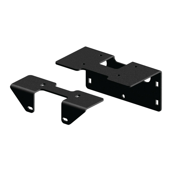
Winch Mount
PART # 101355
Hardware Kit: HK-326
Kit Components:
Item # Qty. Description
1
1
Winch Mount
2
1
Winch Fairlead Plate
3
4
3/8-16 X 1" Short Neck Carriage Bolt
4
4
3/8-16 Hex Flange Nylock Nut
5
2
5/16"-18 X 1-1/4" Hex Flange Bolt
6
2
5/16"-18 Hex Flange Nylock Nut
INSTALLATION INSTRUCTIONS:
Note: Make sure all of the hardware needed to complete this
mount are in the package. Depending on your winch you may
have extra hardware left over when finished installing. Read
through and understand the instructions before installing.
1. Remove the (4) bolts from the front plastic fascia.
Shown in Figure 2.
2. Set winch mount plate (1) and winch (A) upside down
in the opening behind the front frame tubes. Shown in
Figure 3.
3. Attach mount plate (1) loosely to the back of the
frame using the four carriage bolts (3) into the stock
hole location. Shown in Figure 4.
3
"Figure 4" Passenger Side.
©2017 Copyright Kappers Fabricating, Inc. All rights reserved
CF-Moto CForce 400S
Winch Mount
Clutch Side
5
6
"Figure 1"
"Figure 3" Front End
2
1
3
"Figure 2"
1
A
Motor Side
4
Page 1
Advertisement
Table of Contents

Related Manuals for KFI 101355


Summary of Contents for KFI 101355
- Page 1 CF-Moto CForce 400S Winch Mount Winch Mount PART # 101355 Hardware Kit: HK-326 Kit Components: Item # Qty. Description Winch Mount Winch Fairlead Plate 3/8-16 X 1” Short Neck Carriage Bolt 3/8-16 Hex Flange Nylock Nut 5/16”-18 X 1-1/4” Hex Flange Bolt 5/16”-18 Hex Flange Nylock Nut...
- Page 2 4. Attach the rear holes of the winch to the winch mount (1) loosely using the hardware (B) provided with your winch. Shown in Figure 5. 5. Set winch fairlead plate (2) into the in the opening behind the front frame tubes over top of the winch mount plate. Shown in Figure 6. 6. Attach the front holes of the winch through the two plates loosely using the hardware provided with your winch. Shown in Figure 7. 7. Bolt the roller fairlead to the front factory fairlead location on the frame. By inserting the supplied “Figure 5” 5/16 bolts (5) through the fairlead rollers into the threaded frame holes and out the mounting holes. Attach the 5/16 flange nut (6) to the bolts loosely. Shown in Figures 7 & 8. 8. Tighten the rear frame bolts (3) as shown in figure 4, and front fairlead bolts (5) shown in figure 7. Next tighten winch bolts on the top of the mount. “Figure 6” “Figure 8” WIRING INFORMATION 1. The battery location is under the seat. 2. We recommend mounting the contactor next to the battery under the seat.
Need help?
Do you have a question about the 101355 and is the answer not in the manual?
Questions and answers