Advertisement
Winch Mount
Kit Components:
Qty.
Part Description
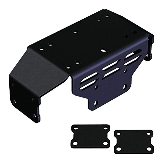
1................. Pioneer Winch Plate
2................. Pioneer Bolt Plate
2................. 5/16"-18 x 1-1/4" x 2" U-Bolt
8................. 5/16"-18 x 2.5" Flange Bolt
12............... 5/16"-18 Flanged Nylock Nut
1................. UTV Mini Rocker Hardware Kit (HK-031)
INSTALLATION INSTRUCTIONS:
1. Place winch plate over bumper as shown in
Figure 3. Loosely secure to the bumper tubes
using the bolt plates, 2.5" bolts and nuts. Figure 2
shows the different bolting locations.
2. Install U-bolts as shown in Figure 4 and tighten
all hardware. Be sure to tighten U-bolts first.
"Figure 3 Mount and Bolt Plate Install"
HONDA PIONEER 500
PART # 101215
Hardware Kit: HK-317, HK-031
"Figure 1"
BOLT PLATE
LOCATION
"Figure 2 Winch Mount Bolting Locations"
"Figure 4 U-bolt Install"
U-BOLT LOCATION
BOLT PLATE
LOCATION
1
Advertisement
Table of Contents

Related Manuals for KFI 101215


Summary of Contents for KFI 101215
- Page 1 HONDA PIONEER 500 Winch Mount PART # 101215 Hardware Kit: HK-317, HK-031 Kit Components: Qty. Part Description 1....Pioneer Winch Plate 2....Pioneer Bolt Plate 2....5/16”-18 x 1-1/4” x 2” U-Bolt 8....5/16”-18 x 2.5” Flange Bolt 12....5/16”-18 Flanged Nylock Nut 1....
- Page 2 Standard 4 Hole Winch Pattern (4.875” x 3”) 3. Determining which winch you have, see Figure 5. 4. Install your roller fairlead to your fairlead plate as shown in Figure 6, using the hardware supplied with your winch. 5. Install your winch and fairlead plate assembly to the mount plate as shown in Figure 7, using Wide 4 Hole Winch Pattern (6.6” x 3”) the hardware provided with your winch and the bolt pattern determined in step 3. CAUTION Make sure to ONLY use the bolts that came with your winch. 6.
- Page 3 WIRING INFORMATION For contactor location please see “Figure 9”. Install the contactor in a location of your choosing under the hood. There is no specific location on this machine. Using the ALTERNATE WINCH WIRING DIAGRAM (AWWD) (Figure 12, pg4) as a guide for steps 2-5, attach the BLACK wire to the Blue Post on the winch and the RED wire to the Yellow Post on the winch. Route the wires up to the contactor and connect the BLACK wire to the Blue Post on the contactor and RED wire to the Yellow Post on the contactor per AWWD. Route the Blue and Yellow wires back to the battery. Connect the YELLOW POS(+) wire to the Red post on the contactor and “Figure 9”...
- Page 4 “AWWD” “Figure 12” Alternate Wiring Diagram Discover other winches on our website.
Need help?
Do you have a question about the 101215 and is the answer not in the manual?
Questions and answers