
Related Manuals for Microchip Technology EVB-USB3503 QFN


Summary of Contents for Microchip Technology EVB-USB3503 QFN
- Page 1 EVB-USB3503 QFN Evaluation Board User’s Guide 2014 Microchip Technology Inc. DS50002252A...
- Page 2 The Microchip name and logo, the Microchip logo, dsPIC, FlashFlex, K logo, MPLAB, PIC, PICmicro, PICSTART, PIC logo, rfPIC, SST, SST Logo, SuperFlash and UNI/O are registered trademarks of Microchip Technology Incorporated in the U.S.A. and other countries. FilterLab, Hampshire, HI-TECH C, Linear Active Thermistor, MTP, SEEVAL and The Embedded Control Solutions Company are registered trademarks of Microchip Technology Incorporated in the U.S.A.
- Page 3 Object of Declaration: EVB-USB3503 QFN Evaluation Board User’s Guide 2014 Microchip Technology Inc. DS50002252A-page 3...
-
Page 4: Table Of Contents
The Microchip Web Site ..................7 Customer Support ....................7 Document Revision History ................... 7 Chapter 1. Overview 1.1 EVB-USB3503 QFN Overview and Features ..........9 1.2 Features ......................9 1.3 General Description ..................9 Chapter 2. Hardware Configuration 2.1 Hardware Description ................... 10 2.1.1 Port Assignment .................. -
Page 5: Preface
• The Microchip Web Site • Customer Support • Document Revision History DOCUMENT LAYOUT This document describes how to use the EVB-USB3503 QFN Evaluation Board as a demonstration platform optimized for portable applications. The manual layout is as follows: •... -
Page 6: Conventions Used In This Guide
EVB-USB3503 QFN Evaluation Board User’s Guide CONVENTIONS USED IN THIS GUIDE This manual uses the following documentation conventions: DOCUMENTATION CONVENTIONS Description Represents Examples Arial font: ® Italic characters Referenced books MPLAB IDE User’s Guide Emphasized text ...is the only compiler... -
Page 7: Warranty Registration
Technical support is available through the web site at: http://www.microchip.com/support DOCUMENT REVISION HISTORY Revision A (March 2014) • Initial Release of this Document. 2014 Microchip Technology Inc. DS50002252A-page 7... - Page 8 EVB-USB3503 QFN Evaluation Board User’s Guide NOTES: 2014 Microchip Technology Inc. DS50002252A-page 8...
-
Page 9: Chapter 1. Overview
USB3503 Ultra Fast USB 2.0 Hub on an RoHS compliant Printed Circuit Board (PCB). The EVB-USB3503 QFN is designed to demonstrate the unique features of this device using a low-cost PCB implementation with ganged port power control for the three downstream USB 2.0 ports. -
Page 10: Chapter 2. Hardware Configuration
Do not exceed 4 A total current consumption from the + 5 VDC power supply. The EVB-USB3503 QFN must be connected to an HSIC upstream host via the DATA (J5) and STROBE (J4) connectors using the provided U.FL coaxial cables. When removing these cables from the EVB for any reason, the provided HSIC Extraction tool must be used. -
Page 11: Usb3503 Configuration
2.1.2 USB3503 Configuration Default: I C configuration is bypassed by default on the EVB-USB3503 QFN evalua- tion board. The hub will use the internal default configuration and automatically transi- tion to the hub communication stage when it is powered on. -
Page 12: Clock Source - 26 Mhz Oscillator
EVB-USB3503 QFN Evaluation Board User’s Guide FIGURE 2-2: HUB_CONNECT SWITCH POSITIONS 2.1.3 Clock Source – 26 MHz Oscillator By default, a 26 MHz oscillator (Y1) is populated on the evaluation board as the clock source for the USB3503. The REFSEL[1:0] pins are used to select the frequency of the clock. -
Page 13: Power Source - Self-Powered
2.1.4 Power Source – Self-Powered The EVB-USB3503 QFN only supports self-powered operation and is powered by one +5 VDC regulated external power supply. The +5 VDC, 4 A power supply plugs into the board via a 2.1 mm connector (J3). The external power supply controls the on board +3.3 VDC voltage regulator and on board +1.8 VDC voltage regulator. -
Page 14: Interrupt Led
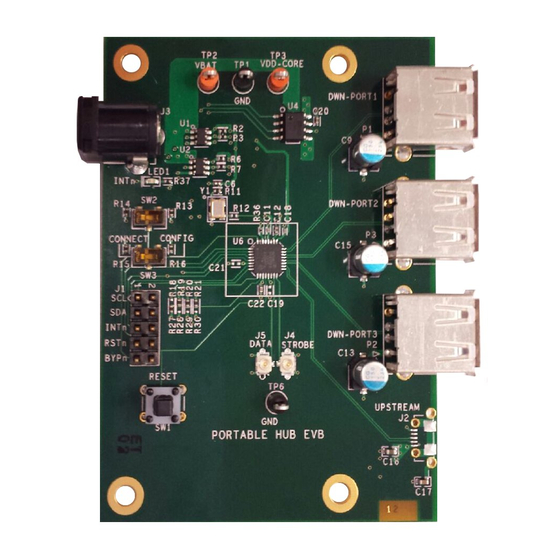
Table 2-3 for the complete list of connectors. See Figure 2-2 for an image of the connectors on the EVB. For more details, please see Appendix A. “EVB-USB3503 QFN Evaluation Board Schemat- ics”. TABLE 2-3: CONNECTOR DESCRIPTION CONNECTOR TYPE DESCRIPTION... - Page 15 FIGURE 2-5: CONNECTOR, TEST POINT, AND SWITCH LOCATIONS Component side top and bottom silk screen layers are shown in Figure 2-6. A block dia- gram of the EVB is shown in Figure 2-7. 2014 Microchip Technology Inc. DS50002252A-page 15...
- Page 16 EVB-USB3503 QFN Evaluation Board User’s Guide FIGURE 2-6: PCB TOP AND BOTTOM SILK SCREEN IMAGES FIGURE 2-7: EVB-USB3503 QFN BLOCK DIAGRAM PORT USB3503 3.3V POWER VBAT PRTPWR 1.8V VDDCORE_REG VBUS PORT VDD33_BYP VDD12_BYP VBUS U.FL CONNECTORS STROBE PORT DATA 1.8V...
-
Page 17: Chapter 3. Operation
Aardvark. Once the software has been installed, locate and run the USB3503 Evalua- tion.exe program on the computer. Connect the Aardvark to the USB3503 EVB with the red wire facing the power port, as in Figure 2014 Microchip Technology Inc. DS50002252A-page 17... -
Page 18: Digital Control
EVB-USB3503 QFN Evaluation Board User’s Guide FIGURE 3-1: AARDVARK CONNECTION The software allows the user to control the digital input pins RESET_N and CONNECT. It also can monitor the INT_N pin for interrupts. There is a section to communicate with the I C serial port, as well as some additional quick configuration and customization options. -
Page 19: I2C Communication
The USB3503 can enumerate as a Self Powered or Bus Powered Hub with 1, 2 or 3 downstream ports. The VID, PID, DID and enumeration strings can also be cus- tomized to allow the USB3503 to enumerate with whatever identification is desired. 2014 Microchip Technology Inc. DS50002252A-page 19... - Page 20 EVB-USB3503 QFN Evaluation Board User’s Guide To change these values; update the configuration section to the desired options, then press the Configure button. The part will then reset, pull the CONNECT pin low and update the registers as specified. To run with these options, either raise the CONNECT pin, or press the Connect button.
-
Page 21: Appendix A. Evb-Usb3503 Qfn Evaluation Board Schematics
EVB-USB3503 QFN EVALUATION BOARD USER’S GUIDE Appendix A. EVB-USB3503 QFN Evaluation Board Schematics INTRODUCTION This appendix shows the EVB-USB3503 QFN Evaluation Board schematics. 2014 Microchip Technology Inc. DS50002252A-page 21... - Page 22 FIGURE A-1: EVB-USB3503 QFN EVALUATION BOARD SCHEMATIC 1...
-
Page 23: Appendix B. Bill Of Materials (Bom)
EVB-USB3503 QFN EVALUATION BOARD USER’S GUIDE Appendix B. Bill of Materials (BOM) INTRODUCTION This appendix shows the EVB-USB3503 QFN Evaluation Board Bill of Materials (BOM). 2014 Microchip Technology Inc. DS50002252A-page 23... - Page 24 TABLE B-1: EVB-USB3503 QFN EVALUATION BOARD BILL OF MATERIALS Item Qty Reference Designator(s) Description Manufacturer Manufacturer Part Number Notes C1 C5 C16 CAPACITOR CERAMIC 4.7UF 10V X5R 0603 TAIYO YUDEN LMK107BJ475KA-T C2 C7 CAPACITOR CERAMIC 18PF 50V 0402 SMD PANASONIC...
- Page 25 TABLE B-1: EVB-USB3503 QFN EVALUATION BOARD BILL OF MATERIALS (CONTINUED) Item Qty Reference Designator(s) Description Manufacturer Manufacturer Part Number Notes SW2 SW3 SWITCH SLIDE SPDT SMD GULL COPAL ELECTRONICS CJS-1200TB TP1 TP6 TEST POINT LOOP COMPACT BLACK KEYSTONE 5006 TP2 TP3...
-
Page 26: Worldwide Sales And Service
Tel: 86-29-8833-7252 Tel: 631-435-6000 Fax: 86-29-8833-7256 San Jose, CA China - Xiamen Tel: 408-735-9110 Tel: 86-592-2388138 Canada - Toronto Fax: 86-592-2388130 Tel: 905-673-0699 China - Zhuhai Fax: 905-673-6509 Tel: 86-756-3210040 10/28/13 Fax: 86-756-3210049 2014 Microchip Technology Inc. DS50002252A-page 26...
Need help?
Do you have a question about the EVB-USB3503 QFN and is the answer not in the manual?
Questions and answers