Table of Contents
Advertisement
Quick Links
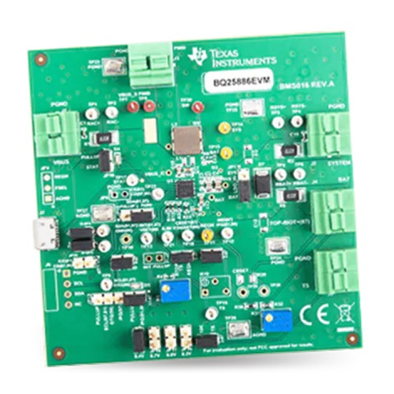
BQ25886 QFN Standalone boost-mode battery charger
This user's guide provides detailed testing instructions for the BQ25886 evaluation module (EVM). Also
included are descriptions of the necessary equipment, equipment setup, procedures, the printed-circuit
board layouts, schematics, and the bill of materials (BOM).
Throughout this user's guide, the abbreviations EVM, BQ25886EVM, BMS016, and the term evaluation
module are synonymous with the BQ25886 QFN evaluation module, unless otherwise noted.
...................................................................................................................
1
1.1
1.2
2
2.1
2.2
2.3
2.4
3
4
4.1
4.2
Schematic
4.3
1
BQ25886 Charge Mode Test Setup
2
3
4
5
6
7
BQ2588xEVM Layer 3
8
9
1
2
3
4
Recommended Operating Conditions
5
SLUUC11 - February 2019
Submit Documentation Feedback
Advance Information
.......................................................................................................
.....................................................................................................
................................................................................................................
...........................................................................................................
........................................................................................................
..........................................................................................................
........................................................................................................
....................................................................................................
.......................................................................................................
..........................................................................................................
....................................................................................................
......................................................................................
.......................................................................................................
..........................................................................................
..........................................................................................................
...............................................................................................
.....................................................................................................
.....................................................................................................
...........................................................................................
.................................................................................................
.........................................................................................................
............................................................................................................
.....................................................................................
..............................................................................................................
BQ25886 QFN Standalone boost-mode battery charger evaluation module
Copyright © 2019, Texas Instruments Incorporated
evaluation module
Contents
........................................................................
List of Figures
List of Tables
.......................................................................
User's Guide
SLUUC11 - February 2019
2
2
2
4
4
5
8
10
10
11
11
12
13
5
7
8
9
11
11
11
11
12
2
2
3
3
13
1
Advertisement
Table of Contents

Subscribe to Our Youtube Channel
Related Manuals for Texas Instruments BQ25886


Summary of Contents for Texas Instruments BQ25886
-
Page 1: Table Of Contents
BQ25886 QFN Standalone boost-mode battery charger evaluation module This user's guide provides detailed testing instructions for the BQ25886 evaluation module (EVM). Also included are descriptions of the necessary equipment, equipment setup, procedures, the printed-circuit board layouts, schematics, and the bill of materials (BOM). -
Page 2: Introduction
Using two series Li-Ion polymer cells is one way to achieve this power increase. Charging these 8.4-V battery packs from a legacy 5-V USB port requires a boost charger. The BQ25886 is a highly- integrated 2-A boosting, 1.5-MHz switch-mode battery charge management device for a 2s Li-Ion and Li- polymer battery. -
Page 3: Evm Jumper Connections And Shunt Installation
— Discharging current through internal MOSFET — — Supply current, I Maximum input current from AC adapter input — SLUUC11 – February 2019 BQ25886 QFN Standalone boost-mode battery charger evaluation module Submit Documentation Feedback Copyright © 2019, Texas Instruments Incorporated... -
Page 4: Test Summary
3 A of current. A current meter in series with the battery or battery simulator must have auto-ranging disabled and should only be used for DC measurements (no start-up, transients, and so forth). BQ25886 QFN Standalone boost-mode battery charger evaluation module SLUUC11 – February 2019 Submit Documentation Feedback... -
Page 5: Charge Mode
4. Turn off BS#1 and PS#1 then attach BS#1 to the BAT (J4) and PGND(J5) terminal of the EVM and attach PS#1 to J1 (VBUS, GND) of the EVM. 5. For and BQ25886, optionally, turn off an electronic load and attach to the J2 (SYS, GND) terminal of the EVM. - Page 6 1.0 A ±5% through a 0.010-Ω ±1% resistor. Voltage of 0.1 mV is added to account for DMM accuracy. 4. Turn off and disconnect PS#1, BS#1, Load#1, and voltmeters. BQ25886 QFN Standalone boost-mode battery charger evaluation module SLUUC11 – February 2019 Submit Documentation Feedback...
-
Page 7: Charge Mode Startup
2.2.3 Charge Mode Evaluation Results Figure 2 shows the Charge Mode Startup graph. Figure 2. Charge Mode Startup SLUUC11 – February 2019 BQ25886 QFN Standalone boost-mode battery charger evaluation module Submit Documentation Feedback Copyright © 2019, Texas Instruments Incorporated... -
Page 8: Otg Mode
3. Measure on VM2 → V(TP1 (VBUS), TP26 (AGND)) = 5.1 V ±160 mV. Voltage of 10 mV is added to account for DMM accuracy. 4. Turn off and disconnect BS#1, Load#1, and voltmeters. BQ25886 QFN Standalone boost-mode battery charger evaluation module SLUUC11 – February 2019 Submit Documentation Feedback... -
Page 9: Otg Mode Startup
2.3.3 OTG Mode Evaluation Results Figure 4 shows the OTG Mode Startup graph. Figure 4. OTG Mode Startup SLUUC11 – February 2019 BQ25886 QFN Standalone boost-mode battery charger evaluation module Submit Documentation Feedback Copyright © 2019, Texas Instruments Incorporated... -
Page 10: Helpful Tips
8. The via size and number must be sufficient for a given current path. See the EVM design for the recommended component placement with trace and via locations.. BQ25886 QFN Standalone boost-mode battery charger evaluation module SLUUC11 – February 2019 Submit Documentation Feedback Copyright ©... -
Page 11: Board Layout, Schematic, And Bill Of Materials
Figure 5. BQ2588xEVM Top Overlay Figure 6. BQ2588xEVM Layer 2 Figure 7. BQ2588xEVM Layer 3 Figure 8. BQ2588xEVM Bottom Overlay SLUUC11 – February 2019 BQ25886 QFN Standalone boost-mode battery charger evaluation module Submit Documentation Feedback Copyright © 2019, Texas Instruments Incorporated... -
Page 12: Bq25886Evm Schematic
MID_/PG STAT CBSET_ICHGSET D-_/PG D+_PSEL ILIM CD_/CE CD_/CE CD_/CE TP23 TP24 TP25 TP26 TP27 SCL_OTG Figure 9. BQ25886EVM Schematic BQ25886 QFN Standalone boost-mode battery charger evaluation module SLUUC11 – February 2019 Submit Documentation Feedback Copyright © 2019, Texas Instruments Incorporated... -
Page 13: Bill Of Materials
V, 3 A, SMB Unless otherwise noted in the Alternate PartNumber and/or Alternate Manufacturer columns, all parts may be substituted with equivalents. SLUUC11 – February 2019 BQ25886 QFN Standalone boost-mode battery charger evaluation module Submit Documentation Feedback Copyright © 2019, Texas Instruments Incorporated... - Page 14 RES, 5.23 k, 1%, CRCW04025K23F 5.23k 0402 Vishay-Dale 0.063 W, 0402 RES, 30.1 k, 1%, CRCW040230K1F 30.1k 0402 Vishay-Dale 0.063 W, 0402 BQ25886 QFN Standalone boost-mode battery charger evaluation module SLUUC11 – February 2019 Submit Documentation Feedback Copyright © 2019, Texas Instruments Incorporated...
- Page 15 TP7, TP8, TP30 5000 Keystone Miniature, Red, TH Testpoint Test Point, Orange Miniature TP11, TP14 Miniature, Orange, 5003 Keystone Testpoint SLUUC11 – February 2019 BQ25886 QFN Standalone boost-mode battery charger evaluation module Submit Documentation Feedback Copyright © 2019, Texas Instruments Incorporated...
- Page 16 152AD NSR10F20NXT5G ON Semiconductor V, 1 A, 152AD Diode, Schottky, 40 V, 0.38 A, SOD- SOD-523 ZLLS350TA Diodes Inc. BQ25886 QFN Standalone boost-mode battery charger evaluation module SLUUC11 – February 2019 Submit Documentation Feedback Copyright © 2019, Texas Instruments Incorporated...
- Page 17 RC0603FR- 0603 Yageo America W, 0603 07300RL Test Point, White Miniature TP10, TP28, TP29 Miniature, White, 5002 Keystone Testpoint SLUUC11 – February 2019 BQ25886 QFN Standalone boost-mode battery charger evaluation module Submit Documentation Feedback Copyright © 2019, Texas Instruments Incorporated...
- Page 18 BQ25886 QFN Standalone boost-mode battery charger evaluation module SLUUC11 – February 2019 Submit Documentation Feedback...
- Page 19 TI products. TI’s provision of these resources does not expand or otherwise alter TI’s applicable warranties or warranty disclaimers for TI products. Mailing Address: Texas Instruments, Post Office Box 655303, Dallas, Texas 75265 Copyright © 2019, Texas Instruments Incorporated SLUUC11 –...
- Page 20 STANDARD TERMS FOR EVALUATION MODULES Delivery: TI delivers TI evaluation boards, kits, or modules, including any accompanying demonstration software, components, and/or documentation which may be provided together or separately (collectively, an “EVM” or “EVMs”) to the User (“User”) in accordance with the terms set forth herein.
- Page 21 www.ti.com Regulatory Notices: 3.1 United States 3.1.1 Notice applicable to EVMs not FCC-Approved: FCC NOTICE: This kit is designed to allow product developers to evaluate electronic components, circuitry, or software associated with the kit to determine whether to incorporate such items in a finished product and software developers to write software applications for use with the end product.
- Page 22 www.ti.com Concernant les EVMs avec antennes détachables Conformément à la réglementation d'Industrie Canada, le présent émetteur radio peut fonctionner avec une antenne d'un type et d'un gain maximal (ou inférieur) approuvé pour l'émetteur par Industrie Canada. Dans le but de réduire les risques de brouillage radioélectrique à...
- Page 23 www.ti.com EVM Use Restrictions and Warnings: 4.1 EVMS ARE NOT FOR USE IN FUNCTIONAL SAFETY AND/OR SAFETY CRITICAL EVALUATIONS, INCLUDING BUT NOT LIMITED TO EVALUATIONS OF LIFE SUPPORT APPLICATIONS. 4.2 User must read and apply the user guide and other available documentation provided by TI regarding the EVM prior to handling or using the EVM, including without limitation any warning or restriction notices.
- Page 24 Notwithstanding the foregoing, any judgment may be enforced in any United States or foreign court, and TI may seek injunctive relief in any United States or foreign court. Mailing Address: Texas Instruments, Post Office Box 655303, Dallas, Texas 75265 Copyright © 2019, Texas Instruments Incorporated...
- Page 25 TI products. TI’s provision of these resources does not expand or otherwise alter TI’s applicable warranties or warranty disclaimers for TI products. Mailing Address: Texas Instruments, Post Office Box 655303, Dallas, Texas 75265 Copyright © 2019, Texas Instruments Incorporated...
Need help?
Do you have a question about the BQ25886 and is the answer not in the manual?
Questions and answers