Table of Contents
Advertisement
Quick Links
bq77915 3-5S Low Power Protector Evaluation Module
This evaluation module (EVM) is a complete evaluation system for the
for lithium-ion cells. The EVM includes one bq77915 and FETs to control current in a configuration typical
for switching current in a lithium-ion battery pack. The circuit module includes one bq77915 integrated
circuit (IC), sense resistors, thermistor, two
necessary to switch charge and discharge current. The circuit module connects between a battery source
and a pack load. In addition to the current and voltage applied to the module, the user can remove
onboard jumpers to simulate overtemperature or undertemperature conditions to observe FET control
under different charge and discharge conditions. Balancing of unmatched cells can also be performed on
the module.
.......................................................................................................................
1
1.1
1.2
1.3
1.4
2
2.1
2.2
2.3
2.4
3
3.1
3.2
3.3
3.4
3.5
3.6
4
4.1
4.2
4.3
4.4
4.5
5
5.1
5.2
6
7
1
2
3
4
Connecting to Cells
5
SLUUBU2B - March 2018 - Revised August 2018
Submit Documentation Feedback
..........................................................................................................
...............................................................................................
......................................................................................................
...........................................................................................
...................................................................................................
...................................................................................................
..............................................................................................
...............................................................................................
...........................................................................................
.................................................................................................
...................................................................................................
...................................................................................................
.................................................................................
.....................................................................................................
..................................................................................
..................................................................................
...........................................................................................
........................................................................................................
.........................................................................................
.......................................................................................................
..........................................................................................................
.............................................................................................................
............................................................................................................
......................................................................................
..........................................................................................................
...................................................................................................
Copyright © 2018, Texas Instruments Incorporated
SLUUBU2B - March 2018 - Revised August 2018
CSD18534Q5A
FETs, and all other onboard components
Contents
...............................................
.................................................................
...............................................................
..........................................................................
......................................................................
.......................................................
bq77915 3-5S Low Power Protector Evaluation Module
User's Guide
bq77915
3-5S low power protector
3
3
3
3
3
3
3
4
4
5
6
6
6
7
8
10
10
10
10
10
10
10
10
11
11
15
17
19
4
6
7
7
9
1
Advertisement
Table of Contents

Related Manuals for Texas Instruments bq77915EVM-014


Summary of Contents for Texas Instruments bq77915EVM-014
-
Page 1: Table Of Contents
Bipolar Operation ..................Operation With Reduced Cell Count ......................Connecting to Cells ....................Stacking Circuit Modules SLUUBU2B – March 2018 – Revised August 2018 bq77915 3-5S Low Power Protector Evaluation Module Submit Documentation Feedback Copyright © 2018, Texas Instruments Incorporated... - Page 2 List of Tables ..................Performance Specification Summary ..................Module Modifications for Stacking ................... bq77915EVM Bill of Materials bq77915 3-5S Low Power Protector Evaluation Module SLUUBU2B – March 2018 – Revised August 2018 Submit Documentation Feedback Copyright © 2018, Texas Instruments Incorporated...
-
Page 3: Features
The bq77915EVM contains the following: • bq77915 circuit module Ordering Information The EVM orderable part number is bq77915EVM-014. For complete ordering information, see the product page at www.ti.com. Documentation For more information on device hardware, refer to bq77915 3-5S Low Power Protector with Cell Balancing and Hibernate Mode. -
Page 4: Items Needed For Evm Quick Start Evaluation
This section covers the hardware connections for the EVM (see Figure Power supply Figure 1. bq77915 Circuit Module Connection for Simple Demonstration bq77915 3-5S Low Power Protector Evaluation Module SLUUBU2B – March 2018 – Revised August 2018 Submit Documentation Feedback Copyright © 2018, Texas Instruments Incorporated... -
Page 5: Quick-Start Sequence
15. Adjust the supply voltage to 18 V to allow recovery from the undervoltage condition. Observe that the pack voltage remains at approximately 0 V with the load resistor in place. SLUUBU2B – March 2018 – Revised August 2018 bq77915 3-5S Low Power Protector Evaluation Module Submit Documentation Feedback Copyright © 2018, Texas Instruments Incorporated... -
Page 6: Additional Evaluation Setups
3 as desired. If the board will be used for further evaluation, be sure to remove the jumper at J8 after the reduced cell test. bq77915 3-5S Low Power Protector Evaluation Module SLUUBU2B – March 2018 – Revised August 2018 Submit Documentation Feedback Copyright © 2018, Texas Instruments Incorporated... -
Page 7: Connecting To Cells
Figure 4. Connecting to Cells SLUUBU2B – March 2018 – Revised August 2018 bq77915 3-5S Low Power Protector Evaluation Module Submit Documentation Feedback Copyright © 2018, Texas Instruments Incorporated... -
Page 8: Stacking Modules
Install BAS16J switching diode Install 10-kΩ resistor Remove shunt Stacking interface Move shunt to pins 15 and 16 bq77915 3-5S Low Power Protector Evaluation Module SLUUBU2B – March 2018 – Revised August 2018 Submit Documentation Feedback Copyright © 2018, Texas Instruments Incorporated... -
Page 9: Stacking Circuit Modules
J6 should be moved to pins 15 and 16 to select the 10-MΩ OCDP resistance, see the data sheet. SLUUBU2B – March 2018 – Revised August 2018 bq77915 3-5S Low Power Protector Evaluation Module Submit Documentation Feedback Copyright © 2018, Texas Instruments Incorporated... -
Page 10: Troubleshooting
3-5S Low Power Protector with Cell Balancing and Hibernate Mode for details and the EVM schematic (Figure 12) for supported resistors. bq77915 3-5S Low Power Protector Evaluation Module SLUUBU2B – March 2018 – Revised August 2018 Submit Documentation Feedback Copyright © 2018, Texas Instruments Incorporated... -
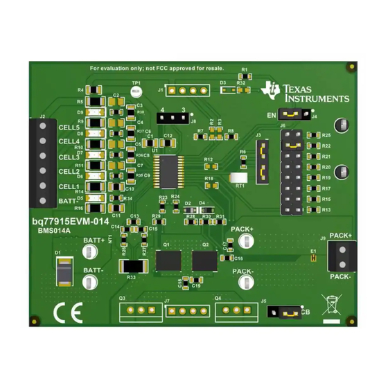
Page 11: Circuit Module Physical Layouts
11). The board is a single-sided assembly, no components are located on the bottom. Figure 6. Top Silk Screen SLUUBU2B – March 2018 – Revised August 2018 bq77915 3-5S Low Power Protector Evaluation Module Submit Documentation Feedback Copyright © 2018, Texas Instruments Incorporated... -
Page 12: Top Assembly
Circuit Module Physical Layouts www.ti.com Figure 7. Top Assembly Figure 8. Top Layer bq77915 3-5S Low Power Protector Evaluation Module SLUUBU2B – March 2018 – Revised August 2018 Submit Documentation Feedback Copyright © 2018, Texas Instruments Incorporated... -
Page 13: Internal Layer
Circuit Module Physical Layouts www.ti.com Figure 9. Internal Layer 1 Figure 10. Internal Layer 2 SLUUBU2B – March 2018 – Revised August 2018 bq77915 3-5S Low Power Protector Evaluation Module Submit Documentation Feedback Copyright © 2018, Texas Instruments Incorporated... -
Page 14: Bottom Layer
Circuit Module Physical Layouts www.ti.com Figure 11. Bottom Layer bq77915 3-5S Low Power Protector Evaluation Module SLUUBU2B – March 2018 – Revised August 2018 Submit Documentation Feedback Copyright © 2018, Texas Instruments Incorporated... -
Page 15: Schematic
PACK- Output 0.015 0 - 22 V PACK+ 0.1uF 0.1uF 0.1uF 0.1uF Figure 12. bq77915EVM Schematic SLUUBU2B – March 2018 – Revised August 2018 bq77915 3-5S Low Power Protector Evaluation Module Submit Documentation Feedback Copyright © 2018, Texas Instruments Incorporated... -
Page 16: Bq77915Evm Cell Balance Indicator Schematic
Circuit Module Physical Layouts www.ti.com 1.00k 1.00k 1.00k 1.00k 1.00k Figure 13. bq77915EVM Cell Balance Indicator Schematic bq77915 3-5S Low Power Protector Evaluation Module SLUUBU2B – March 2018 – Revised August 2018 Submit Documentation Feedback Copyright © 2018, Texas Instruments Incorporated... -
Page 17: Bill Of Materials
Unless otherwise noted in the Alternate Part Number or Alternate Manufacturer columns, all parts may be substituted with equivalents. SLUUBU2B – March 2018 – Revised August 2018 bq77915 3-5S Low Power Protector Evaluation Module Submit Documentation Feedback Copyright © 2018, Texas Instruments Incorporated... - Page 18 RES, 10.0k, 1%, 0.1W, 0603 0603 CRCW060310K0FKEA Vishay-Dale 470k RES, 470k, 5%, 0.1W, 0603 0603 CRCW0603470KJNEA Vishay-Dale bq77915 3-5S Low Power Protector Evaluation Module SLUUBU2B – March 2018 – Revised August 2018 Submit Documentation Feedback Copyright © 2018, Texas Instruments Incorporated...
-
Page 19: Related Documentation From Texas Instruments
• Texas Instruments, bq77915 3-5S Low Power Protector with Cell Balancing and Hibernate Mode Data Sheet SLUUBU2B – March 2018 – Revised August 2018 bq77915 3-5S Low Power Protector Evaluation Module Submit Documentation Feedback Copyright © 2018, Texas Instruments Incorporated... - Page 20 Changes from Original (March 2018) to A Revision ....................... Page .................... • Updated Cell Balance Indicators section ......................• Updated Top Silkscreen image Revision History SLUUBU2B – March 2018 – Revised August 2018 Submit Documentation Feedback Copyright © 2018, Texas Instruments Incorporated...
- Page 21 STANDARD TERMS FOR EVALUATION MODULES Delivery: TI delivers TI evaluation boards, kits, or modules, including any accompanying demonstration software, components, and/or documentation which may be provided together or separately (collectively, an “EVM” or “EVMs”) to the User (“User”) in accordance with the terms set forth herein.
- Page 22 FCC Interference Statement for Class B EVM devices NOTE: This equipment has been tested and found to comply with the limits for a Class B digital device, pursuant to part 15 of the FCC Rules. These limits are designed to provide reasonable protection against harmful interference in a residential installation.
- Page 23 【無線電波を送信する製品の開発キットをお使いになる際の注意事項】 開発キットの中には技術基準適合証明を受けて いないものがあります。 技術適合証明を受けていないもののご使用に際しては、電波法遵守のため、以下のいずれかの 措置を取っていただく必要がありますのでご注意ください。 1. 電波法施行規則第6条第1項第1号に基づく平成18年3月28日総務省告示第173号で定められた電波暗室等の試験設備でご使用 いただく。 2. 実験局の免許を取得後ご使用いただく。 3. 技術基準適合証明を取得後ご使用いただく。 なお、本製品は、上記の「ご使用にあたっての注意」を譲渡先、移転先に通知しない限り、譲渡、移転できないものとします。 上記を遵守頂けない場合は、電波法の罰則が適用される可能性があることをご留意ください。 日本テキサス・イ ンスツルメンツ株式会社 東京都新宿区西新宿6丁目24番1号 西新宿三井ビル 3.3.3 Notice for EVMs for Power Line Communication: Please see http://www.tij.co.jp/lsds/ti_ja/general/eStore/notice_02.page 電力線搬送波通信についての開発キットをお使いになる際の注意事項については、次のところをご覧ください。http:/ /www.tij.co.jp/lsds/ti_ja/general/eStore/notice_02.page 3.4 European Union 3.4.1 For EVMs subject to EU Directive 2014/30/EU (Electromagnetic Compatibility Directive): This is a class A product intended for use in environments other than domestic environments that are connected to a low-voltage power-supply network that supplies buildings used for domestic purposes.
- Page 24 Notwithstanding the foregoing, any judgment may be enforced in any United States or foreign court, and TI may seek injunctive relief in any United States or foreign court. Mailing Address: Texas Instruments, Post Office Box 655303, Dallas, Texas 75265 Copyright © 2018, Texas Instruments Incorporated...
- Page 25 IMPORTANT NOTICE FOR TI DESIGN INFORMATION AND RESOURCES Texas Instruments Incorporated (‘TI”) technical, application or other design advice, services or information, including, but not limited to, reference designs and materials relating to evaluation modules, (collectively, “TI Resources”) are intended to assist designers who are developing applications that incorporate TI products;...
Need help?
Do you have a question about the bq77915EVM-014 and is the answer not in the manual?
Questions and answers