Table of Contents
Advertisement
Quick Links
DPR-350 User Manual Ver_01
DESCRIPTION
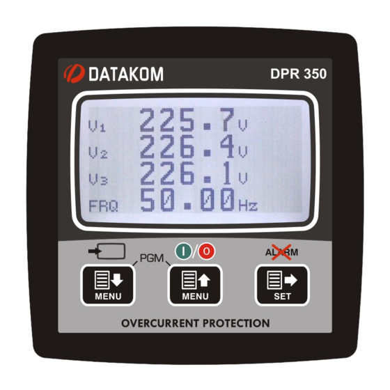
DPR-350 is a state of the art network analyzer and
protection relay in 96x96 standard panel dimensions.
Thanks to its low depth, it provides space economy.
The DPR-350 features dual current measurement
circuits. It is both a precise analyzer and a protection
relay. Protection curves can be selected among IEC,
ANSI, UK and US standards. Multiple protection curves
can be activated simultaneously.
Multiple measurements can be viewed on the 128x64
pixel graphic display of the device.
The unit records every electrical parameter to its built-in
1MB (16MB optional) memory at the desired sampling
rate. The records can be read via Modbus.
Through its RS-485 port, the unit can connect to various
Scada systems and can be remotely monitored.
Parameter configuration is done via USB port.
The unit offers 4 digital inputs, 2 relay outputs, and 3
analog outputs as standard. Analog outputs can be used
to receive desired measurements in the form of 4-20mA
signals, or to drive a visual fault mechanism.
PROTECTION CURVES
• IEC Standard / Very / Extreme Inverse
• UK Long Term Inverse,
• IEEE Medium / Very / Extreme Inverse
• US Normal Inverse, Short Time Inverse
COMMUNICATIONS
• USB 2.0 PC connection
• RS-485 (isolated) 2400-115200 baud
• Modbus RTU
• IEC60870-5-103 communication protocol
RECORD MEMORY
• 35x event records with time stamp.
• 15.000 periodic records with time stamp.
• Adjustable sampling rate.
• 1MB total record memory.
ANALYZER MEASUREMENTS
• Phase voltages: V1-V2-V3-U12-U23-U31
• Phase currents: I1-I2-I3-Ineutral
• Active power:
P1-P2-P3-∑P
•
Reactive power: Q1-Q2-Q3-∑Q
•
Apparent power: S1-S2-S3-∑S
•
Power factor: cos1-cos2-cos3-∑cos
• Frequency: F
• Negative sequence currents and voltages
• Zero sequence currents and voltages
• T32Q value
DPR 350
NETWORK ANALYZER &
PROTECTION RELAY
FEATURES
• 128x64 pixels graphic displays
• % 0.5 accuracy OG analyzer features
• 4 quadrant energy counters
• Multiple protection curves
• 1MB records memory
• Self-test, internal failure monitoring
• Cold reclosure
• Configurable optically isolated digital inputs
• Configurable relay outputs
• Configurable analog outputs
• 2 independent configuration sets
• English menus
• Setup parameters on the device
• 3-level password protection
• Connection via USB or RS-485
• Free PC configuration software
• Manual open/close from front panel and
Scada
• Software update via USB
• Wide supply voltage range: 19-150V
• IP65 protection with optional gasket
• Low panel depth
STANDARDS
•
EN60255 Electrical Relays
•
EN61010 Safety Requirements
•
EN61326 Electromagnetic Compatibility
•
EN60068 Environmental Conditions
•
EN60529 Protection Levels
PROTECTION FUNCTIONS
ANSI CODE DESCRIPTION
50,51
Overcurrent
46
Negative Sequence Overcurrent
67
Directional Overcurrent
50BF
Breaker Failure
79
Reclosure
Firmware V-1.0
DC
Advertisement
Table of Contents

Subscribe to Our Youtube Channel
Related Manuals for Datakom DPR-350 Series


Summary of Contents for Datakom DPR-350 Series
- Page 1 DPR-350 User Manual Ver_01 Firmware V-1.0 DPR 350 DESCRIPTION NETWORK ANALYZER & DPR-350 is a state of the art network analyzer and PROTECTION RELAY protection relay in 96x96 standard panel dimensions. Thanks to its low depth, it provides space economy. The DPR-350 features dual current measurement FEATURES circuits.
- Page 2 DPR-350 family units. Follow the advice given in the document carefully. These are often good practices for the installation of the units which reduce future issues. For all technical queries please contact Datakom at the e-mail address below: technical.support@datakom.com.tr QUERRIES...
- Page 3 DPR-350 User Manual Ver_01 Firmware V-1.0 RELATED DOCUMENTS FILENAME DESCRIPTION Rainbow Installation Rainbow Plus Installation Guide Rainbow Usage Rainbow Plus Usage Guide TERMINOLOGY CAUTION: Potential risk of injury or death. WARNING: Potential risk of malfunction or material damage. ATTENTION: Useful hints for the understanding of device operation. ORDERING CODES The DPR-350 family units are available in various options and peripheral features.
- Page 4 DPR-350 User Manual Ver_01 Firmware V-1.0 SPARE PARTS Screw type bracket Self-Retaining type bracket Stock Code=J10P01 (per unit) Stock Code=K16P01 (per unit) Sealing Gasket, Stock Code= J63P01...
- Page 5 DPR-350 User Manual Ver_01 Firmware V-1.0 SAFETY NOTICE Failure to follow below instructions will result in death or serious injury. ▪ Electrical equipment should only be installed by a qualified specialist. No responsibility is assured by the manufacturer or any of its subsidiaries for any consequences resulting from the non-compliance to these instructions.
-
Page 6: Table Of Contents
DPR-350 User Manual Ver_01 Firmware V-1.0 TABLE OF CONTENTS 1. INSTALLATION INSTRUCTIONS 2. MOUNTING 2.1. DIMENSIONS 2.2. MECHANICAL INSTALLATION 2.3. SEALING GASKET 2.4. ELECTRICAL INSTALLATION 3. TERMINAL TECHNICAL SPECIFICATIONS 3.1. SUPPLY VOLTAGE INPUT 3.2. AC VOLTAGE INPUTS 3.3. AC CURRENT INPUTS 3.4. - Page 7 DPR-350 User Manual Ver_01 Firmware V-1.0 16. MIN-MAX VALUES 17. DISPLAYING EVENT LOGS 18. PROTECTIONS & ALARMS 19. PROGRAMMING 19.1. ENTERING PROGRAM MODE 19.2. NAVIGATING BETWEEN MENUS 19.3. MODIFYING PARAMETER VALUE 19.4. EXITING PROGRAM MODE 20. PROGRAM PARAMETER LIST 20.1. CONTROLLER CONFIGURATION GROUP 20.2.
-
Page 8: Installation Instructions
DPR-350 User Manual Ver_01 Firmware V-1.0 1. INSTALLATION INSTRUCTIONS Before installation: ▪ Read the user manual carefully, determine the correct connection diagram. ▪ Remove all connectors and mounting brackets from the unit, then pass the unit through the mounting opening. ▪... -
Page 9: Mounting
DPR-350 User Manual Ver_01 Firmware V-1.0 2. MOUNTING 2.1. DIMENSIONS Dimensions: 102x102x53mm (4.0”x4.0”x2.0”) Installation: Panel mounted, rear retaining plastic brackets. Weight: 200g (0.44 lb) 2.2. MECHANICAL INSTALLATION Panel Cutout Required Panel Depth The unit is designed for panel mounting. The user should not be able to access parts of the unit other than the front panel during normal operation. - Page 10 DPR-350 User Manual Ver_01 Firmware V-1.0 Mount the unit on a flat, vertical surface. Before mounting, remove the mounting brackets and connectors from the unit, then pass the unit through the mounting opening. Place and tighten mounting brackets. Two different types of brackets are provided: Self-retaining type bracket Screw type bracket Installation of self-retaining type bracket...
-
Page 11: Sealing Gasket
DPR-350 User Manual Ver_01 Firmware V-1.0 2.3. SEALING GASKET Panel Gasket Module The rubber gasket (sold separately) provides a watertight means of mounting the module to the panel. With the gasket, IEC 60529-IP65 protection is provided. A short definition of IP protection levels is given below: Digit 0 Not protected... -
Page 12: Electrical Installation
DPR-350 User Manual Ver_01 Firmware V-1.0 2.4. ELECTRICAL INSTALLATION Do not install the unit close to high electromagnetic noise emitting devices like contactors, high current busbars, switchmode power supplies, etc. Although the unit is protected against electromagnetic disturbance, excessive disturbance can affect the operation, measurement precision and data communication quality. -
Page 13: Terminal Technical Specifications
DPR-350 User Manual Ver_01 Firmware V-1.0 3. TERMINAL TECHNICAL SPECIFICATIONS 3.1. SUPPLY VOLTAGE INPUT AC SUPPLY TYPES: 100-265VAC(±%15), 50-60Hz (±%10), 88- Power Supply Voltage: 400VDC DC SUPPLY TYPES: 24-110VDC (±%20) Reverse Voltage: Directionless inputs, operates with both polarities. Maximum Input Power: 15 VA Isolation: 3500VAC/1minute from all other terminals. -
Page 14: Ac Current Inputs
DPR-350 User Manual Ver_01 Firmware V-1.0 3.3. AC CURRENT INPUTS Structure: Isolated, integrated current transformers Measurement Method: True RMS Sampling Rate: 8192 Hz CT Secondary Rating: CT Range: 5/5 - 25000/5A minimum Input Impedance: 15 milliohms Burden: 0.375W @ 5A Maximum Current: 6A continuous Measurement Range:... - Page 15 DPR-350 User Manual Ver_01 Firmware V-1.0 CORRECT CT CONNECTIONS Suppose that each phase of the utility mains are loaded with 100 kW. The power factor (PF) for the load is as follows: kVAr Phase L1 100.0 1.00 Phase L2 100.0 1.00 Phase L3 100.0...
-
Page 16: Digital Inputs
DPR-350 User Manual Ver_01 Firmware V-1.0 EFFECT OF PHASE SWAPPING The utility mains is still loaded with 100 kW on each phase. PF in phases L2 and L3 will show -0.50 due to phase shift between voltages and currents which is caused by CT swapping. As a result, the total power displayed will be 0 kW. - Page 17 The RS-485 port supports MODBUS-RTU protocol. Multiple modules may be paralleled on the same RS- 485 line in order to provide data transfer to automation or building management systems. The Modbus register list is available at Datakom technical support. The RS-485 port provides an effective solution for distant PC connection to enable programming and monitoring via SCADA software.
-
Page 18: Usb Port
The USB port is designed to provide PC connection with the controller. Programming and monitoring can be done via RainbowPlus program. The RainbowPlus program is available for free on www.datakom.com.tr. The connector type is Mini-USB. The cable type is the commonly available camera cable. -
Page 19: Topologies
DPR-350 User Manual Ver_01 Firmware V-1.0 4. TOPOLOGIES Topologies are selected from program parameters. Mains grid topologies are shown in the picture below. 4.1. TOPOLOGY SELECTION Configuration Screen Electrical Parameters Topology Selection... -
Page 20: Phase, 4 Wire, Star
DPR-350 User Manual Ver_01 Firmware V-1.0 4.2. 3 PHASE, 4 WIRE, STAR 4.3. 3 PHASE, 3 WIRE, DELTA... -
Page 21: Phase, 4 Wire, Delta
DPR-350 User Manual Ver_01 Firmware V-1.0 4.4. 3 PHASE, 4 WIRE, DELTA 4.5. 3 PHASE, 3 WIRE, DELTA, 2 CT (L1-L2) -
Page 22: Phase, 3 Wire, Delta, 2 Ct (L1-L3)
DPR-350 User Manual Ver_01 Firmware V-1.0 4.6. 3 PHASE, 3 WIRE, DELTA, 2 CT (L1-L3) 4.7. 2 PHASE, 3 WIRE, DELTA, 2 CTs (L1-L2) -
Page 23: Phase, 2 Wire
DPR-350 User Manual Ver_01 Firmware V-1.0 4.8. 1 PHASE, 2 WIRE... -
Page 24: Connection Diagram
DPR-350 User Manual Ver_01 Firmware V-1.0 5. CONNECTION DIAGRAM... -
Page 25: Technical Specifications
DPR-350 User Manual Ver_01 Firmware V-1.0 6. TECHNICAL SPECIFICATIONS Power Supply Input: 19 - 150VDC Power Consumption: < 4 W / 15VA Nominal Frequency: 50/60 Hz Phase CT Secondary Rating: 1A/5A 0.1 – 25.0 A AC Protection Current Range: Measuring Inputs: 0.001 –... -
Page 26: Terminal Descriptions
DPR-350 User Manual Ver_01 Firmware V-1.0 7. TERMINAL DESCRIPTIONS Terminal Function Technical Data Description 19 – 150V DC AUXILIARY SUPPLY + Supply input positive terminal. No connection. 19 – 150V DC AUXILIARY SUPPLY - Supply input negative terminal. Terminal Function Technical Data Description Phase inputs,... -
Page 27: Description Of Controls
DPR-350 User Manual Ver_01 Firmware V-1.0 8. DESCRIPTION OF CONTROLS 8.1. FRONT PANEL FUNCTIONALITY Graphical LCD Display Previous screen within the same group Next screen within the same group Next display group 8.2. PUSHBUTTON FUNCTIONS BUTTON FUNCTION Move to next display group. Hold pressed for 3 seconds: Reset all alarms. -
Page 28: Measured Parameters
DPR-350 User Manual Ver_01 Firmware V-1.0 8.3. MEASURED PARAMETERS The controller measures multiple analog parameters with high accuracy. List of measured parameters is given below: L1-N voltage L1 active power (kW) L2-N voltage L2 active power (kW) L3-N voltage L3 active power (kW) L1-L2 voltage L1 reactive power (kVAr) L2-L3 voltage... -
Page 29: Display Symbols
DPR-350 User Manual Ver_01 Firmware V-1.0 9. DISPLAY SYMBOLS SYMBOL DESCRIPTION Firmware version Phase 1 - Phase 2 AC RMS Voltage Phase 2 - Phase 3 AC RMS Voltage Phase 3 - Phase 1 AC RMS Voltage Frequency Phase 1 - Neutral AC RMS Voltage Phase 2 - Neutral AC RMS Voltage Phase 3 - Neutral AC RMS Voltage Phase 1 AC RMS Current... -
Page 30: Automatic Display Scroll
DPR-350 User Manual Ver_01 Firmware V-1.0 9.1. AUTOMATIC DISPLAY SCROLL The controller measures many electrical parameters. The viewing of these parameters is organized into DISPLAY GROUPS and their sub categories. Moving between different display groups is done by button. Each time is pressed, the next parameter group screen is displayed. -
Page 31: Protection Functions
DPR-350 User Manual Ver_01 Firmware V-1.0 10. PROTECTION FUNCTIONS 10.1. GENERAL FEATURES DPR-350 offers overcurrent protection relay functionality in order to protect and manage transmission lines. Supported ANSI protection functions are listed below: Overcurrent Protection (ANSI 50/51) Negative Sequence Overcurrent Protection (ANSI 46) Directional Overcurrent Protection (ANSI 67) Breaker Failure (ANSI 50BF) Circuit Connection Supervision (ANSI 74) -
Page 32: Time Calculation For Curves
DPR-350 User Manual Ver_01 Firmware V-1.0 10.2. TIME CALCULATION FOR CURVES The DPR-350 controller offers constant time and 12 different variable time curves for protection functions. Current / time curves are usually calculated using the equation below: Here : t(I) = Trip time as a function of input current I I = Instantaneous secondary current value of the phase Is = Fault threshold for secondary current T = Time coefficient (TD for IEEE, TMS for IEC) -
Page 33: Overcurrent Protection (Ansi 50/51)
DPR-350 User Manual Ver_01 Firmware V-1.0 The DPR-350 offers the following parameters to configure protection functions: PARAMETER DESCRIPTION VALID CURVES Status Protection is activated or deactivated. Function Protection curve Direct. Direction setting for directional protection Set Val (Is) Fault threshold for current Time Dly (T) Constant time protection time (T) Time multiplier for IEC curves... -
Page 34: Directional Overcurrent Protection (Ansi 67)
DPR-350 User Manual Ver_01 Firmware V-1.0 10.5. DIRECTIONAL OVERCURRENT PROTECTION (ANSI 67) If the voltage and current of one phase are in the same direction, the current is flowing from the source to the load, which means it is forward directional. If the voltage and current of one phase are in opposite directions, the current is flowing from the load to the source, which means it is reverse directional. -
Page 35: Cold Load Pickup (Clpu 50/51)
DPR-350 User Manual Ver_01 Firmware V-1.0 10.8. COLD LOAD PICKUP (CLPU 50/51) Cold load pickup operation is used to prevent unwanted conditions while energizing after long duration power losses. Temporary pulse currents which exceed protection threshold values may be formed when restoring power, depending on the characteristics of the network’s load. -
Page 36: Mimic Diagram
DPR-350 User Manual Ver_01 Firmware V-1.0 11. MIMIC DIAGRAM The controller offers a mimic diagram screen which displays the breaker position. This screen is the factory default upon the device being powered on. In addition, the device shows this screen if no keys have been pressed for 1 minute. -
Page 37: Astronomic Timer Relay Function
DPR-350 User Manual Ver_01 Firmware V-1.0 12. ASTRONOMIC TIMER RELAY FUNCTION The astronomic relay function enables the unit to accurately calculate sunrise and sunset times according to date and location. This function allows the user to operate streetlamps according to sunrise and sunset hours, and also activating and deactivating various systems. -
Page 38: User Screen Configuration
DPR-350 User Manual Ver_01 Firmware V-1.0 13. USER SCREEN CONFIGURATION The unit offers a flexible and easy to use screen design tool in programming mode. The user can freely design a needed screen. Any measured value can be displayed using 2 different character sizes. -
Page 39: Counters
DPR-350 User Manual Ver_01 Firmware V-1.0 14. COUNTERS Counters The unit features counters for statistical calculations. These counters are stored in non-volatile device memory and maintain their values even if the unit is powered off. The unit also features counters which count signal pulses for digital inputs. This allows for counting and reading external events with communication channels. -
Page 40: Demand Values
DPR-350 User Manual Ver_01 Firmware V-1.0 15. DEMAND VALUES Demand values are the average of the measured values over a given period. Average values are compared with the demand values at the end of each period. If the new value is greater than the demand value, the new value is recorded as the demand value. - Page 41 DPR-350 User Manual Ver_01 Firmware V-1.0 17. DISPLAYING EVENT RECORDS The unit records more than 35 events with date-time and measurement values at the time of the event. Event records include the following: -Event ordinal number -Event type / fault definition (detailed later in this section) -date and time -alarm/input/output bits -Ph-N voltages: V1-V2-V3...
- Page 42 DPR-350 User Manual Ver_01 Firmware V-1.0 Event records can be viewed from the programming menu. This prevents confusion of the event records with other measurements. To enter Event Records menu, press together buttons for 5 seconds. The following password prompt will be displayed upon entering program mode. Enter the password Hold...
-
Page 43: Protections & Alarms
DPR-350 User Manual Ver_01 Firmware V-1.0 18. PROTECTIONS & ALARMS If any of the analog values of the measured parameters are outside the configured limits cause an ALARM situation. In case of a fault condition, the alarm pop-up screen is displayed and the alarm function is activated. Alarm status can be assigned to a relay output in order to control various systems. -
Page 44: Programming
DPR-350 User Manual Ver_01 Firmware V-1.0 19. PROGRAMMING Programming mode is used to configure timers, operation limits and parameters. Every parameter can be changed from the front panel of the device as well as via the free Rainbow Plus software. Parameter changes are automatically recorded to non-volatile memory and are effective immediately. -
Page 45: Navigating Between Menus
DPR-350 User Manual Ver_01 Firmware V-1.0 19.2. NAVIGATING BETWEEN MENUS The programming mode is organized into a 2-level menu system. Main menu is composed of program groups. Program parameters are located within the groups. Upon entering the programming mode, the list of program groups is displayed. Navigation between groups is done using buttons. -
Page 46: Exiting Program Mode
DPR-350 User Manual Ver_01 Firmware V-1.0 19.4. EXITING PROGRAM MODE In order to exit program mode, press and hold the buttons together for 5 seconds. The controller exits the program mode automatically if there is no action after 2 minutes. Press and hold for 5 seconds... -
Page 47: Program Parameter List
DPR-350 User Manual Ver_01 Firmware V-1.0 20. PROGRAM PARAMETER LIST 20.1. CONTROLLER CONFIGURATION GROUP Parameter Definition Unit Factory Description Setting 0: English 1: Turkish. This option can vary Language Selection according to the country of use. Different languages can be uploaded using Rainbow Plus software. -
Page 48: Electrical Parameters Group
DPR-350 User Manual Ver_01 Firmware V-1.0 20.2. ELECTRICAL PARAMETERS GROUP Parameter Definition Unit Factory Description Setting Current Transformer Enter the primary and secondary values 25000/1 600/1 Ratio for the current transformer. Voltage transformer ratio. This ratio is multiplied by the values measured in Voltage Transformer 5000 the voltage and power measurements. - Page 49 DPR-350 User Manual Ver_01 Firmware V-1.0 20.2. ELECTRICAL PARAMETERS GROUP Parameter Definition Unit Factory Description Setting If the reactive power of any channel is capacitive and above this limit, an Reactive Capacitive kVAr 9999 alarm occurs. Alarm If this value is set to 0, the alarm is not checked.
- Page 50 DPR-350 User Manual Ver_01 Firmware V-1.0 20.2. ELECTRICAL PARAMETERS GROUP Parameter Definition Unit Factory Description Setting 0: non-latching THD-I Alarm Latching 1: latching If voltage unbalance exceeds his value, an alarm occurs. If this value is set to 0, the alarm is not Voltage Unbalance Alarm checked.
-
Page 51: Input Parameters
DPR-350 User Manual Ver_01 Firmware V-1.0 20.3. INPUT PARAMETERS The unit features 4 digital inputs. The parameters of one digital input are explained below. The other input functions have identical parameters. Input functions can be assigned user defined strings. This enables digital inputs to be used in any function. -
Page 52: Output Parameters
DPR-350 User Manual Ver_01 Firmware V-1.0 20.4. OUTPUT PARAMETERS The parameters below determine the functions of the unit’s digital outputs. The unit features 2 relay outputs and each can be configured as one of the functions listed below. The following is a short list of output functions. Use the RainbowPlus software for the complete list. -
Page 53: Analog Outputs
DPR-350 User Manual Ver_01 Firmware V-1.0 20.5. ANALOG OUTPUTS The unit features 3 analog outputs. Any measurement value selected from the list can be assigned to any output. Values can be set for 4mA and 20mA. Each channel has its distinct program block. Analog Output 1 Setting Analog output-1 Program Parameters Analog Output 2 Setting... -
Page 54: Input & Display Strings
DPR-350 User Manual Ver_01 Firmware V-1.0 20.6. INPUT & DISPLAY STRINGS In this parameter group, user input strings and digital input names can be entered. 20.7. RESETTING THE COUNTERS In this parameter group, the counters and the demand period of measurements can be reset and configured. -
Page 55: Calibration
DPR-350 User Manual Ver_01 Firmware V-1.0 20.9. CHANGING SERIAL NUMBER The device’s serial number can be changed from this menu. 20.10. CALIBRATION The unit is calibrated before it leaves the factory, but it is possible to recalibrate. In “PROGRAMMING” mode, go to “CALIBRATION”. Then, select the measurement using the buttons and press the button. -
Page 56: Changing The Password
DPR-350 User Manual Ver_01 Firmware V-1.0 20.12. CHANGING THE PASSWORD The unit has 3 levels of password protection. Each password is a 4 digit number. The password can only be changed at the factory. 20.13. FACTORY RESET When this menu is selected, the device will ask for confirmation. Select the desired value with the buttons and push the button to set it and... -
Page 57: Overcurrent Protection (Ansi 50/51)
DPR-350 User Manual Ver_01 Firmware V-1.0 20.15. OVERCURRENT PROTECTION (ANSI 50/51) The controller offers 2 levels of overcurrent protection, each with its own distinct parameter group. Parameter Definition Description Factory Setting I> Parameters for level 1 protection IEC, 1.00In, TMS=0.1 I>>... -
Page 58: Breaker Failure (Ansi 50Bf)
DPR-350 User Manual Ver_01 Firmware V-1.0 20.17. BREAKER FAILURE (ANSI 50BF) The unit offers single level breaker failure protection. If the fault condition persists after the trip command has been sent to the breaker and the configured timer expires, this function is activated. The function status can be assigned to a relay output. -
Page 59: Cold Load Pickup
DPR-350 User Manual Ver_01 Firmware V-1.0 20.19. COLD LOAD PICKUP This feature is used to prevent unnecessary trips which may occur in cases where the load is powered up suddenly after remaining unpowered for a long period of time. Only valid for “OVERCURRENT PROTECTION (ANSI 50/51)”. -
Page 60: Internal Records Memory
DPR-350 User Manual Ver_01 Firmware V-1.0 21. INTERNAL RECORDS MEMORY The unit’s 1 MB internal memory can store 15000 records, 64 bytes each. Record frequency configuration parameter: CONTROLLER CONFIGURATION>Internal Record Period. The records can be read via Modbus. For detailed information on record reading, please refer to MODBUS COMMUNICATION section. -
Page 61: Modbus Communications
DPR-350 User Manual Ver_01 Firmware V-1.0 22. MODBUS COMMUNICATIONS The unit offers MODBUS in the following modes: -RS485 serial port, adjustable baud rate from 2400 to 115200 MODBUS features of the device: -Data transfer mode: RTU -Serial data: adjustable baud rate, 8 bit data, no parity, 1 bit stop -Supported functions: -Function 3 (read multiple registers) -Function 6 (write single register) - Page 62 DPR-350 User Manual Ver_01 Firmware V-1.0 22.3. READING DATA Record reading is performed using function code 03 (read multiple registers). The MODBUS master device sends a query. The response can be either the required data or an error message. Up to 123 registers can be read at once.
-
Page 63: Data Writing
DPR-350 User Manual Ver_01 Firmware V-1.0 Error return message: BYTE DESCRIPTION VALUE Device Address Same as query Function code 131 (Function code+128) Error Code 2 (invalid address) CRC Bottom Byte CRC calculation is explained below CRC Top Byte CRC calculation is explained below 22.4. -
Page 64: Crc Calculation
DPR-350 User Manual Ver_01 Firmware V-1.0 22.5. CRC CALCULATION Follow the method shown below for CRC calculation, 1) A 16-bit variable named CRC with every bit set to 1 is initialized. 2) The result of the Boolean logic operation XOR of the bottom byte of CRC and the first byte of the message (Function Code) is appended to CRC. - Page 65 DPR-350 User Manual Ver_01 Firmware V-1.0 R/W TYPE REGISTER VARIABLE DESCRIPTION SIZE ADDRESS (BIT) Unsigned 16 BIT x1000 Current / Current Transformer Ratio word Unsigned Frequency Mains Frequency 16 BIT x100 word Unsigned P1/(VT Ratio/CT Ratio) 16 BIT word Unsigned P2/(VT Ratio/CT Ratio) 16 BIT word...
-
Page 66: Commands
DPR-350 User Manual Ver_01 Firmware V-1.0 22.7. COMMANDS REGISTER VARIABLE DESCRIPTION SIZE (BIT) TYPE ADDRESS 16384 Password Programming Password W-O Unsigned word 16385 Button Button Simulation W-O Unsigned word 16386 Factory Factory Reset W-O Unsigned word 16387 Reset Reset All Counters W-O Unsigned Counter word... -
Page 67: Real Time Clock (Rtc)
DPR-350 User Manual Ver_01 Firmware V-1.0 22.8. REAL TIME CLOCK (RTC) REGISTER VARIABLE DESCRIPTION SIZE (BIT) TYPE ADDRESS 8192 Year Year (0-4096) R-O Unsigned word 8193 Month Month (1-12) R-O Unsigned word 8194 Day (1-31) R-O Unsigned word 8195 Weekday Day of the week (0-6) R-O Unsigned word... -
Page 68: Measurements
DPR-350 User Manual Ver_01 Firmware V-1.0 22.10. MEASUREMENTS REGISTER VARIABLE DESCRIPTION SIZE TYPE ADDRESS V1 Phase – Neutral Voltage 20480 V1 RMS R-O Unsigned long x10 V2 Phase – Neutral Voltage 20482 V2 RMS R-O Unsigned long x10 V3 Phase – Neutral Voltage 20484 V3 RMS R-O Unsigned long x10... - Page 69 DPR-350 User Manual Ver_01 Firmware V-1.0 REGISTER VARIABLE DESCRIPTION SIZE TYPE ADDRESS 21048- Scope Oscilloscopic Data 16 BIT R-O Signed word 21147 21148- Relay F. Relay Functions Status Bits 16 BIT R-O Array 4x16 bit - 21151 21152 Anl_1_Val Analog Output 1 ADC 16 BIT R-O Unsigned word...
- Page 70 DPR-350 User Manual Ver_01 Firmware V-1.0 22.11. FUNCTION ALARM BITS BIT DESCRIPTION BIT DESCRIPTION 16 Input-1 Alarm 0 High Voltage 17 Input-2 Alarm 1 Low Voltage 2 High Frequency 18 Input-3 Alarm 19 Input-4 Alarm 3 Low Frequency 4 High kW 20 High Neutral Current 5 Low kW 21 Auxiliary...
-
Page 71: Demand-Min-Max
DPR-350 User Manual Ver_01 Firmware V-1.0 22.12. DEMAND-MIN-MAX REGISTER VARIABLE DESCRIPTION SIZE TYPE ADDRESS 12308 In_1_Pulse Input-1 Pulse Counter 32 BIT R-O unsigned long 10 12310 In_2_Pulse Input-2 Pulse Counter 32 BIT R-O unsigned long 10 12312 In_3_Pulse Input-3 Pulse Counter 32 BIT R-O unsigned long 10 12314... -
Page 72: Declaration Of Conformity
DPR-350 User Manual Ver_01 Firmware V-1.0 23. DECLARATION OF CONFORMITY The unit conforms to the EU directives: -2014/35/EC (Low Voltage) -2014/30/EC (electro-magnetic compatibility) Norms of Reference: EN 61010 (safety requirements) EN 61326 (EMC requirements) The CE mark indicates that this product complies with the European requirements for safety, health, environmental and customer protection.
Need help?
Do you have a question about the DPR-350 Series and is the answer not in the manual?
Questions and answers