Table of Contents
Advertisement
DKM-411 User Manual Rev_01
DESCRIPTION
The DKM-411 is an advanced precision metering
device offering an 3.5" size, 320x240 pixel color TFT,
together with unrivalled remote monitoring
capabilities over internet in a compact and low cost
package.
The unit itself is a web page and can be opened
through any browser for remote monitoring.
The central monitoring feature allows monitoring of
thousands of meters from one central PC.
The unit complies and mostly exceeds world's
tightest safety, EMC and environmental standards
for the industrial category.
Software features are complete with easy firmware
upgrade process through USB port.
The Windows based PC software allows monitoring
and programming through USB, RS-485, Ethernet
and GPRS.
The PC based Rainbow Scada software allows
monitoring and control of an unlimited number of
devices from a single central location.
COMMUNICATION PORTS
Ethernet 10/100Mb
RS-485 isolated (Modbus RTU)
RS-232 for external GPRS modem
USB Host for data recording on flash memory
USB Device for PC connection
DKM-411
ADVANCED
NETWORK
ANALYSER WITH
INTERNET
COMMUNICATIONS
FEATURES
True RMS measurements
3.5" TFT LCD, 320x240 pixels
Internal battery backed-up real time clock
Harmonic distortion display (63 harmonics)
Oscilloscope, waveform display
Phasor diagram display
Max demand display
User configurable display screens
2 configurable relay outputs
Free internet based monitoring program
2 opto-isolated, configurable digital inputs
Dual active-reactive power counters
Both mains & generator energy metering
Configurable user counters
Voltage transformer ratio for MV applications
Password protected front panel programming
Reduced panel depth
Sealed front panel (IP54)
TOPOLOGIES
3 phases 4 wires, star
3 phases 3 wires, 3 CTs
3 phases 3 wires, 2 CTs (L1-L2)
3 phases 3 wires, 2 CTs (L1-L3)
3 phases 4 wires, delta
2 phases 3 wires, L1-L2
1 phase 2 wires
Firmware V-1.0
Advertisement
Table of Contents

Related Manuals for Datakom DKM-411


Summary of Contents for Datakom DKM-411
- Page 1 ANALYSER WITH INTERNET COMMUNICATIONS DESCRIPTION FEATURES The DKM-411 is an advanced precision metering True RMS measurements device offering an 3.5” size, 320x240 pixel color TFT, 3.5” TFT LCD, 320x240 pixels together with unrivalled remote monitoring Internal battery backed-up real time clock...
- Page 2 DKM-411 family units. Follow carefully advices given in the document. These are often good practices for the installation of genset control units which reduce future issues. For all technical queries please contact Datakom at below e-mail address: datakom@datakom.com.tr QUERRIES...
- Page 3 GSM Configuration Guide Firmware Update Firmware Update Guide 411-MODBUS Modbus Application Manual for DKM-411 411-snmp_E_34076_DKM411 MIB file for SNMP Application of DKM-411 Rainbow Scada Installation Rainbow Scada Installation Guide Rainbow Scada Usage Rainbow Scada Usage Guide TERMINOLOGY CAUTION: Potential risk of injury or death.
- Page 4 DKM-411 User Manual Rev_01 Firmware V-1.0 ORDERING CODES The DKM-411 family units are available in various options and peripheral features. Please use below information for ordering the correct version: DKM-411 -G -T -00 Variant 00: standard unit With Sealing With Conformal 01...99: customer...
- Page 5 DKM-411 User Manual Rev_01 Firmware V-1.0 SAFETY NOTICE Failure to follow below instructions will result in death or serious injury Electrical equipment should be installed only by qualified specialist. No responsibility is assured by the manufacturer or any of its subsidiaries for any consequences resulting from the non-compliance to these instructions.
-
Page 6: Table Of Contents
DKM-411 User Manual Rev_01 Firmware V-1.0 TABLE OF CONTENTS 1.INSTALLATION INSTRUCTIONS 2.MOUNTING 2.1. DIMENSIONS 2.2. SEALING, GASKET 2.3. ELECTRICAL INSTALLATION 3. TERMINAL DESCRIPTIONS 3.1. AUXILIARY SUPPLY INPUT 3.2. AC VOLTAGE INPUTS 3.3. AC CURRENT INPUTS 3.4. DIGITAL INPUTS 3.5. DIGITAL OUTPUTS 3.6. - Page 7 DKM-411 User Manual Rev_01 Firmware V-1.0 19. PROGRAMMING 19.1. ENTERING THE PROGRAMMING MODE 19.2. NAVIGATING BETWEEN MENUS 19.3. MODIFYING PARAMETER VALUE 19.4. PROGRAMMING MODE EXIT 19.5. RESETTING TO FACTORY SET PARAMETERS 20. PROGRAM PARAMETER LIST 20.1. CONTROLLER CONFIGURATION GROUP 20.2. ELECTRICAL PARAMETERS GROUP 20.3.
-
Page 8: Installation Instructions
DKM-411 User Manual Rev_01 Firmware V-1.0 1. INSTALLATION INSTRUCTIONS Before installation: Read the user manual carefully, determine the correct connection diagram. Remove all connectors and mounting brackets from the unit, then pass the unit through the mounting opening. -
Page 9: Mounting
DKM-411 User Manual Rev_01 Firmware V-1.0 2. MOUNTING 2.1. DIMENSIONS Dimensions: 102x102x49mm (4.0”x4.0”x2.0”) Panel Cutout: 92x92mm minimum (3.62”x3.62”) Weight: 480g (1.1 lb) K46D03-EN - 9 -... - Page 10 DKM-411 User Manual Rev_01 Firmware V-1.0 The unit is designed for panel mounting. The user should not be able to access parts of the unit other than the front panel. Mount the unit on a flat, vertical surface. Before mounting, remove the mounting brackets and connectors from the unit, then pass the unit through the mounting opening.
- Page 11 DKM-411 User Manual Rev_01 Firmware V-1.0 Two different types of brackets are provided: Screw type bracket Self retaining type bracket Installation of self retaining type bracket Installation of screw type bracket Do not tighten too much, this may break the unit.
-
Page 12: Sealing, Gasket
DKM-411 User Manual Rev_01 Firmware V-1.0 2.2. SEALING, GASKET Panel Gasket Module The rubber gasket provides a watertight means of mounting the module to the genset panel. Together with the gasket, 60529-IP65 protection can be reached from the front panel. A short definition of IP protection levels is given below. -
Page 13: Electrical Installation
DKM-411 User Manual Rev_01 Firmware V-1.0 2.3. ELECTRICAL INSTALLATION Do not install the unit close to high electromagnetic noise emitting devices like contactors, high current busbars, switchmode power supplies and the like. Although the unit is protected against electromagnetic disturbance, excessive disturbance can affect the operation, measurement precision and data communication quality. -
Page 14: Terminal Descriptions
DKM-411 User Manual Rev_01 Firmware V-1.0 3. TERMINAL DESCRIPTIONS 3.1. AUXILIARY SUPPLY INPUT Supply voltage: 90 to 300V AC DC supply version: 19-150V DC Maximum operating 20mA (All options included, digital outputs open.) current: Maximum operating power: < 5VA (All options included, digital outputs open.) Isolation 3500VAC/1minute from all other terminals. -
Page 15: Ac Voltage Inputs
DKM-411 User Manual Rev_01 Firmware V-1.0 3.2. AC VOLTAGE INPUTS Measurement method: True RMS Sampling rate: 8000 Hz Harmonic analysis: up to 63th harmonic Input voltage range: 0 to 300 VAC Supported topologies: 3 ph 4 wires star 3 ph 3 wires delta... -
Page 16: Ac Current Inputs
DKM-411 User Manual Rev_01 Firmware V-1.0 3.3. AC CURRENT INPUTS Measurement method: True RMS Sampling rate: 8000 Hz Harmonic analysis: up to 63th harmonic Supported topologies: 3 ph 3 CTs 3 ph 2 CTs L1-L2 3 ph 2 CTs L1-L3... - Page 17 SELECTING THE CT ACCURACY CLASS: The CT accuracy class should be selected in accordance with the required measurement precision. The accuracy class of the Datakom controller is 0.5%. Thus 0.5% class CTs are advised for the best result. CONNECTING CTs: Be sure of connecting each CT to the related phase input with the correct polarity.
- Page 18 DKM-411 User Manual Rev_01 Firmware V-1.0 CORRECT CT CONNECTIONS Let’s suppose that the genset is loaded with 100 kW on each phase. The load Power Factor (PF) is 1. Measured values are as follows: kVAr Phase L1 100.0 1.00 Phase L2 100.0...
- Page 19 DKM-411 User Manual Rev_01 Firmware V-1.0 EFFECT OF POLARITY REVERSAL The network is still loaded with 100 kW On each phase. The load Power Factor (PF) is 1. PF in phase L2 will show -1,00 due to reverse CT polarity. The result is that total measured power displayed by the analyser is 100 kW.
-
Page 20: Digital Inputs
DKM-411 User Manual Rev_01 Firmware V-1.0 3.4. DIGITAL INPUTS Function selection: from list Number of inputs: 2 inputs, all configurable Contact type: Normally open or normally closed (programmable) Structure: Opto-isolated with 10 k-ohms serial resistor. Isolation voltage: 1000VAC, 1 minute... -
Page 21: Digital Outputs
DKM-411 User Manual Rev_01 Firmware V-1.0 3.5. DIGITAL OUTPUTS Structure: Isolated relay output, normally open contact. One terminal is internally connected to relay common terminal Number of outputs: 2 outputs, both configurable Function selection: from list Max switching current: 5A @250VAC/30VDC... -
Page 22: Rs-485 Port
The RS-485 port features MODBUS-RTU protocol. Multiple modules (up to 128) can be paralleled on the same RS-485 bus for data transfer to automation or building management systems. The Modbus register list is available at Datakom technical support. The RS-485 port provides also a good solution for distant PC connection where RainbowPlus program will enable programming, control and monitoring. - Page 23 DKM-411 User Manual Rev_01 Firmware V-1.0 RS-485 BUS STRUCTURE A maximum of 32 devices can be paralleled on a RS-485 bus. For more devices on one bus, repeaters must be used. 120R 120R The bus must be terminated from both ends with 120 ohm resistor.
-
Page 24: Ethernet Port
DKM-411 User Manual Rev_01 Firmware V-1.0 3.7. ETHERNET PORT Description: IEEE802.3 compliant, 10/100 Base-TX RJ45 ethernet port with indicating leds Data rate: 10/100 Mbits/s, auto detecting Connector: RJ45 Cable type: CAT5 or CAT6 Isolation: 1500 VAC, 1 minute Max distance: 30m. -
Page 25: Usb Device Port
The RainbowPlus software can be downloaded from www.datakom.com.tr website. The connector on the module is of USB-B type. Thus A to B type USB cable should be used. This is the same cable used for USB printers. -
Page 26: Usb Host Port
DKM-411 User Manual Rev_01 Firmware V-1.0 3.9. USB HOST PORT USB HOST Port USB FLASH MEMORY Description: USB 2.0, not isolated Power Supply 5V, 300mA max Output: Data rate: Full Speed 1.5/12 Mbits/s, auto detecting Connector: USB-A (PC type connector) Cable length: Max 1.5m... -
Page 27: Modem Port
8 bit data, no parity, 1 bit stop Max distance: Cable type: Special cable, provided by manufacturer Terminal description: 1: +5V supply (50mA max) 2: Rx input 3: Tx output 4: DTR output 5: GND The modem connection cable is available at Datakom. K46D03-EN - 27 -... -
Page 28: External Gsm Modem (Dkg-090)
DKM-411 User Manual Rev_01 Firmware V-1.0 3.11. EXTERNAL GSM MODEM (DKG-090) The optional external GSM modem is fully compatible with the unit. It does not require any special setup. The 1800/1900 MHz magnetic antenna together with its 2 meter cable is supplied with the modem. The antenna is intended to be placed outside of the control panel for the best signal reception. - Page 29 DKM-411 User Manual Rev_01 Firmware V-1.0 MODEM CABLE DIAGRAM DKM-411 USB PLUG DKG-090 MODEM (D-SUB 9 PIN FEMALE) 1: +5V supply (50mA max) ………………………….. 6 2: Rx input ………………………………………………2 (Tx output) 3: Tx output …………………………………………… 3 (Rx input) 4: DTR output ………………………………………… 1 5: GND …………………………………………………...
-
Page 30: Topologies
DKM-411 User Manual Rev_01 Firmware V-1.0 4. TOPOLOGIES Various topologies are selectable through program parameter. In following drawings the connections are shown for the alternator. Current transformers are supposed connected to the alternator side. Similar topologies re available for the mains side as well. -
Page 31: Phase, 4 Wire, Star
DKM-411 User Manual Rev_01 Firmware V-1.0 4.2. 3 PHASE, 4 WIRE, STAR 4.3. 3 PHASE, 3 WIRE, DELTA K46D03-EN - 31 -... -
Page 32: Phase, 4 Wire, Delta
DKM-411 User Manual Rev_01 Firmware V-1.0 4.4. 3 PHASE, 4 WIRE, DELTA 4.5. 3 PHASE, 3 WIRE, DELTA, 2 CT (L1-L2) K46D03-EN - 32 -... -
Page 33: Phase, 3 Wire, Delta, 2 Ct (L1-L3)
DKM-411 User Manual Rev_01 Firmware V-1.0 4.6. 3 PHASE, 3 WIRE, DELTA, 2 CT (L1-L3) 4.7. 2 PHASE, 3 WIRE, DELTA, 2 CTs (L1-L2) K46D03-EN - 33 -... -
Page 34: Phase, 2 Wire
DKM-411 User Manual Rev_01 Firmware V-1.0 4.8. 1 PHASE, 2 WIRE K46D03-EN - 34 -... -
Page 35: Connection Diagram
DKM-411 User Manual Rev_01 Firmware V-1.0 5. CONNECTION DIAGRAM K46D03-EN - 35 -... -
Page 36: Terminal Description
DKM-411 User Manual Rev_01 Firmware V-1.0 6. TERMINAL DESCRIPTION Term Function Technical data Description AUXILIARY SUPPLY 85 to 300VAC Aux supply terminal Do not connect this terminal. AUXILIARY SUPPLY 85 to 300VAC Aux supply terminal Term Function Technical data Description... -
Page 37: Technical Specifications
DKM-411 User Manual Rev_01 Firmware V-1.0 7. TECHNICAL SPECIFICATIONS Power Supply Input: 100-240V AC nominal(± 20%) 50 - 60Hz nominal (± 10%) DC input types available. Power Consumption: < 5 VA Measurement Input Range: Voltage: 5 - 300 V AC (L-N) -
Page 38: Description Of Controls
DKM-411 User Manual Rev_01 Firmware V-1.0 8. DESCRIPTION OF CONTROLS 8.1. FRONT PANEL FUNCTIONALITY The front panel comprises a 320x240 pixels 3.5” color LCD display and 4 multi-function pushbutton keys. The top section of the display is reserved for menu and status indications. This area displays the active menu, internet connection status and date-time information. -
Page 39: Pushbutton Functions
DKM-411 User Manual Rev_01 Firmware V-1.0 8.2. PUSHBUTTON FUNCTIONS BUTTON FUNCTION Selects next display screen in the same display group. WHEN HELD PRESSED FOR 5 SECONDS: Makes the current display screen the default screen that comes up at power-on. Selects previous display group. -
Page 40: Display Screen Organization
DKM-411 User Manual Rev_01 Firmware V-1.0 8.3. DISPLAY SCREEN ORGANIZATION The unit measures a large number of electrical parameters. The display of the parameters is organized as PARAMETER GROUPS and items in a group. Navigation between different groups are made with buttons. - Page 41 DKM-411 User Manual Rev_01 Firmware V-1.0 K46D03-EN - 41 -...
-
Page 42: Measured Parameters
DKM-411 User Manual Rev_01 Firmware V-1.0 8.4. MEASURED PARAMETERS The unit performs a detailed set of AC measurements. The list of measured parameters is below L1-N voltage L1 active power (kW) L2-N voltage L2 active power (kW) L3-N voltage L3 active power (kW) -
Page 43: Waveform Display & Harmonic Analysis
DKM-411 User Manual Rev_01 Firmware V-1.0 9. WAVEFORM DISPLAY & HARMONIC ANALYSIS The unit features waveform display together with a precision harmonic analyzer for voltages and currents. Both phase to neutral and phase to phase voltages are available for analysis, thus 9 channels in total are possible. - Page 44 DKM-411 User Manual Rev_01 Firmware V-1.0 The harmonic analyzer consists on a Fast Fourier Transform (FFT) algorithm which is run twice a second on all channels. The sample memory is 1024 samples long and 13 bits resolution with a sampling rate of 8192 s/s.
-
Page 45: Phasor Diagram
DKM-411 User Manual Rev_01 Firmware V-1.0 10. PHASOR DIAGRAM The unit offers a Phasor diagram display presenting the phasing of all voltage and current inputs. The reference phase is the voltage input V1 (L1-N voltage). This is the long vertical segment drawn in red color. -
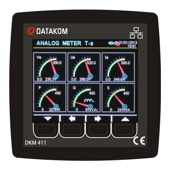
Page 46: Analog Displays
DKM-411 User Manual Rev_01 Firmware V-1.0 11. ANALOG DISPLAYS Various analog displays are provided for the ease of reading. Each analog display page consists of 6 gauges, presented in various combinations. Yellow and green zones in gauges are directly picked up from warning and alarm levels, providing check- up at a glance. -
Page 47: User Configurable Display Screens
DKM-411 User Manual Rev_01 Firmware V-1.0 13. USER CONFIGURABLE DISPLAY SCREENS The device offers a powerful user screen design tool through programming menu. The user can freely design his own screen for the most specialized functionality. Any measured value may be set on the display, using 2 different possible font sizes. -
Page 48: Power Counters & Incremental Counters
DKM-411 User Manual Rev_01 Firmware V-1.0 14. POWER COUNTERS & INCREMENTAL COUNTERS The unit provides a set of incremental counters for statistical purposes. These counters are stored in a non-volatile memory and retain their values even when power is off. -
Page 49: Demand Values
DKM-411 User Manual Rev_01 Firmware V-1.0 15. DEMAND VALUES Demand values are average values of measured parameters over a 15 minute period. The unit starts a demand calculation period every 15 minutes (synchronized to the real time clock). The average values at the end of the period are compared with the demand registers, if higher, the new demand is stored into the register. -
Page 50: Displaying Event Logs
DKM-411 User Manual Rev_01 Firmware V-1.0 17. DISPLAYING EVENT LOGS The unit features more than 400 event logs with date-time stamp and full snapshot of measured values at the moment that the event has occurred. Stored values in an event record are listed below:... - Page 51 DKM-411 User Manual Rev_01 Firmware V-1.0 Event logs are displayed within the program mode menu. This is designed in order to reduce the interference of event logs with other measurement screens. To enter the event display, press together with buttons for 5 seconds.
-
Page 52: Protections And Alarms
DKM-411 User Manual Rev_01 Firmware V-1.0 18. PROTECTIONS AND ALARMS The device is able to generate fault conditions on adjustable limits of measured parameters. Fault cases are considered under two categories, namely alarm and warnings: 1- ALARMS: These are the most important fault conditions. -
Page 53: Programming
DKM-411 User Manual Rev_01 Firmware V-1.0 19. PROGRAMMING The program mode is used to adjust timers, operational limits and the configuration of the unit. Although a free PC program is provided for programming, every parameter may be modified through the front panel, regardless of the operating mode. -
Page 54: Navigating Between Menus
DKM-411 User Manual Rev_01 Firmware V-1.0 19.2. NAVIGATING BETWEEN MENUS The program mode is driven with a two level menu system. The top menu consists on program groups and each group consists on various program parameters. When program mode is entered, a list of available groups will be displayed. Navigation between different groups are made with buttons. - Page 55 DKM-411 User Manual Rev_01 Firmware V-1.0 Navigation inside a group is made also with buttons. A list of available parameters will be displayed. The selected parameter is shown in a different color. In order to display/change the value of this parameter, please press...
-
Page 56: Modifying Parameter Value
DKM-411 User Manual Rev_01 Firmware V-1.0 19.3. MODIFYING PARAMETER VALUE Parameter value may be increased and decreased with buttons. If these keys are held pressed, the program value will increase/decrease at a faster speed. When a program parameter is modified, it is automatically saved in memory. -
Page 57: Programming Mode Exit
DKM-411 User Manual Rev_01 Firmware V-1.0 19.4. PROGRAMMING MODE EXIT To exit the program mode press buttons together during 5 seconds. If no button is pressed during 2 minutes the program mode will be cancelled automatically. Press 2 buttons for 5... -
Page 58: Resetting To Factory Set Parameters
DKM-411 User Manual Rev_01 Firmware V-1.0 19.5. RESETTING TO FACTORY SET PARAMETERS In order to resume to the factory set parameter values: -Enter programming mode with password “9876”, button until displaying the “RETURN TO FACTORY SET” menu. -press -press button. The factory set dialog box will appear. -
Page 59: Program Parameter List
DKM-411 User Manual Rev_01 Firmware V-1.0 20. PROGRAM PARAMETER LIST 20.1. CONTROLLER CONFIGURATION GROUP Parameter Definition Unit Factory Description LCD Backlight The intensity of the LCD back light. 0: English language selected. Language 1: Local language selected. This language may be downloaded. - Page 60 DKM-411 User Manual Rev_01 Firmware V-1.0 20.1. CONTROLLER CONFIGURATION GROUP (continued) Parameter Definition Unit Factory Description 0: No event log on output change Output Event Log Enable 1: Event logged on output change 0: No event logging on intput change...
-
Page 61: Electrical Parameters Group
DKM-411 User Manual Rev_01 Firmware V-1.0 20.2. ELECTRICAL PARAMETERS GROUP Parameter Definition Unit Factory Description This is the rated value of current 2’000/1 Current Transformer transformers. All transformers must 500/5 10’000/5 Configuration have the same rating. The secondary of the transformer will be 5 Amps. - Page 62 DKM-411 User Manual Rev_01 Firmware V-1.0 20.2. ELECTRICAL PARAMETERS GROUP (continued) If the reactive capacitive power goes Reactive Capacitive 9’999 kVAr over this limit, this will generate a Power High Alarm Limit HIGH REACTIVE POWER alarm. If the reactive inductive power goes Reactive Inductive Power 9’999...
- Page 63 DKM-411 User Manual Rev_01 Firmware V-1.0 20.2. ELECTRICAL PARAMETERS GROUP (continued) If the THD of any current channel goes THD-I High Alarm Limit over this limit, this will generate a HIGH THD-I alarm. When the THD-I goes over the limit,...
-
Page 64: Counters Min/Max Parameters Group
DKM-411 User Manual Rev_01 Firmware V-1.0 20.3. COUNTERS MIN/MAX PARAMETERS GROUP When this parameter is set to 1, then Restart Min/Max MIN/MAX values are reset. Set Meter1 (kWh1- The counter value can be adjusted with 65’535 Import) Value this parameter. -
Page 65: Digital Input Configuration
DKM-411 User Manual Rev_01 Firmware V-1.0 20.4. DIGITAL INPUT CONFIGURATION The unit has 2 digital inputs. Only parameters of one input are explained below. Other input have identical parameter set. The input name is freely programmable, thus the input can be adapted to any functionality through programming. - Page 66 DKM-411 User Manual Rev_01 Firmware V-1.0 INPUT FUNCTION LIST Number Function Description User Function 1 User defined function. User Function 2 User defined function. User Function 3 User defined function. User Function 4 User defined function. User Function 5 User defined function.
-
Page 67: Output Configuration
DKM-411 User Manual Rev_01 Firmware V-1.0 20.5. OUTPUT CONFIGURATION The parameters below define the functions of relay outputs. The unit has 2 relay outputs. Each relay has programmable functions, selected from a list. OUTPUT FUNCTION LIST Number Function Description Horn Alarm relay output. -
Page 68: User Input Strings
DKM-411 User Manual Rev_01 Firmware V-1.0 20.6. USER INPUT STRINGS The device has several user defined strings that are used in measurement presentation or fault localization. Number Function Description 00-07 Input Strings These are function names associated with digital inputs. -
Page 69: Configuring User Display Screens
DKM-411 User Manual Rev_01 Firmware V-1.0 20.7. CONFIGURING USER DISPLAY SCREENS The device offers 4 user configurable display screens capable of presenting all available measurements in 2 different sizes. These screens can be configured as the default screen, therefore the user can transform the unit into a specialized measurement instrument tailored on specific needs. - Page 70 DKM-411 User Manual Rev_01 Firmware V-1.0 The screen header is also programmable through “USER INPUT STRINGS” menu. A sample user screen LIST OF SELECTABLE PARAMETERS L1-N Voltage THD L1-N Voltage Maximum L2-3 Voltage L2-N Voltage THD L2-N Voltage Maximum L3-1 Voltage...
-
Page 71: Site-Id String
DKM-411 User Manual Rev_01 Firmware V-1.0 20.8. SITE-ID STRING The site identity string is designed to identify the current device. This is the site Id string sent at the beginning of SMS messages, e-mails and web page headers for the identification of the device sending the message. -
Page 72: Gsm Modem Parameters
DKM-411 User Manual Rev_01 Firmware V-1.0 20.12. GSM MODEM PARAMETERS Parameter Definition Description The APN (access point name) username may be required by the GSM operator. However some GSM operators may allow access without APN User Name username. The exact information should be obtained from the GSM operator. -
Page 73: Ethernet Parameters
DKM-411 User Manual Rev_01 Firmware V-1.0 20.13. ETHERNET PARAMETERS Parameter Definition Factory Set Description This is the IPv4 (internet protocol version 4) address that the unit will require from the DHCP (dynamic host control protocol) server. Network IP Address 0.0.0.0 If this parameter is set to 0.0.0.0 then the unit will... - Page 74 Factory Set Description This is the account name appearing in the “from” tab Mail Account Name d500_a of the e-mail recipient. (ex: datakom-d500@gmail.com) Mail Account d500_1234 This is the e-mail password of above e-mail account. Password This is the Outgoing Mail Server Address of the above Mail Server Address smtp.mail.yahoo.com...
-
Page 75: Ethernet Configuration
DKM-411 User Manual Rev_01 Firmware V-1.0 21. ETHERNET CONFIGURATION Please see related document: Ethernet Configuration Guide for D-500 D-700. 22. GSM CONFIGURATION Please see related document: GSM Configuration Guide for D-500 D-700. 23. DYNAMIC DNS FEATURE Please see related document: Dynamic DNS Account Setting for D-500 D-700. -
Page 76: Accessing The Embedded Web Server
DKM-411 User Manual Rev_01 Firmware V-1.0 24. ACCESSING THE EMBEDDED WEB SERVER The embedded web server is accessible through the IP address of the controller, using the ETHERNET connection. The IP address is displayed at the top of ETHERNET screen. - Page 77 DKM-411 User Manual Rev_01 Firmware V-1.0 Counters Page Alarm List Page Event Log Display Page Please see related document: Ethernet Configuration Guide for D-500 D-700for more details. K46D03-EN - 77 -...
-
Page 78: Web Monitoring
DKM-411 User Manual Rev_01 Firmware V-1.0 25. WEB MONITORING Please see related document: Ethernet Configuration Guide for D-500 D-700. 26. CENTRAL MONITORING Please see related document: Rainbow Scada Usage Guide. 27. E-MAIL SENDING Please see related document: Ethernet Configuration Guide for D-500 D-700. -
Page 79: Sms Commands
DKM-411 User Manual Rev_01 Firmware V-1.0 29. SMS COMMANDS SMS messages are accepted only from phone numbers recorded in the Communication>GSM>Message Numbers tab. Answers to SMS messages will be sent to all phone numbers in the list. SMS messages must be written exactly as below, without any preceding blanks. -
Page 80: Data Recording
DKM-411 User Manual Rev_01 Firmware V-1.0 30. DATA RECORDING 30.1. DATA RECORDING MEDIA Data can be recorded in USB flash memory. As soon as a USB flash memory is inserted, the unit will start data recording and continue until the memory is removed. -
Page 81: Directory Structure
DKM-411 User Manual Rev_01 Firmware V-1.0 30.2. DIRECTORY STRUCTURE The unit will record data in a USB-Flash memory. The record structure is below: Year 2013 Last day of SITE-ID the year Year 2012 First day of Previous years the year The unit will record data in a directory named with the first 11 characters of its site-id parameter. -
Page 82: Recorded Data List, Record Period
DKM-411 User Manual Rev_01 Firmware V-1.0 30.4. RECORDED DATA LIST, RECORD PERIOD The recording period is adjustable between 10 seconds and 18 hours by program parameter. A short period will give better resolution, but it will store more data in the memory card, therefore a larger capacity will be required. -
Page 83: Modbus Communications
DKM-411 User Manual Rev_01 Firmware V-1.0 31. MODBUS COMMUNICATIONS This chapter is a brief description of the Modbus properties of the device. For a complete documentation please use: “DKM-411 Modbus Application Manual” The unit offers the possibility of MODBUS communication through below carriers:... -
Page 84: Parameters Required For Rs-485 Modbus Operation
Ethernet Gateway IP: Should be set in accordance with your local switch configuration. Ethernet Subnet Mask: Should be set in accordance with your local switch configuration. Please rewiev the document Ethernet Configuration Guide for DKM-411 for more details about the ethernet port setup. - Page 85 DKM-411 User Manual Rev_01 Firmware V-1.0 Below is a shortlist of available Modbus registers. For complete register map please refer to DKM-411 Modbus Application Manual. ADDRESS R / W DATA COEFF. DESCRIPTION (decimal) SIZE 20480 32bit Phase L1 voltage 20482...
-
Page 86: Snmp Communications
User IP Mask: There are 3 mask registers available. The use of the registers are emphasized in the DKM-411 User Manual. Please set the first mask as 255.255.255.0 for the proper operation. Ethernet Network IP: May be left as 0.0.0.0 for automatic address claim or set to a value in order to claim a defined address. -
Page 87: Calibration
DKM-411 User Manual Rev_01 Firmware V-1.0 33. CALIBRATION Calibration can be modified only with a special password. The unit is factory calibrated but it is possible to recalibrate it in order to obtain equal display values on different measuring instruments. -
Page 88: Declaration Of Conformity
DKM-411 User Manual Rev_01 Firmware V-1.0 34. DECLARATION OF CONFORMITY The unit conforms to the EU directives -2006/95/EC (low voltage) -2004/108/EC (electro-magnetic compatibility) Norms of reference: EN 61010 (safety requirements) EN 61326 (EMC requirements) The CE mark indicates that this product complies with the European requirements for safety, health, environmental and customer protection. -
Page 89: Disposal Of The Unit
“Monitoring and control instruments including industrial monitoring and control instruments” and exempted from ROHS directive. However Datakom is not using any ROHS uncompliant electronic components in the production. Only the solder contains lead. The switching to unleaded solderin is in progress. K46D03-EN... -
Page 90: Troubleshooting Guide
DKM-411 User Manual Rev_01 Firmware V-1.0 38. TROUBLESHOOTING GUIDE Below is a basic list of most often encountered troubles. More detailed investigation may be required in some cases. No display: External fusing for the power supply voltage has tripped. Switch fuse on or replace fuse. - Page 91 DKM-411 User Manual Rev_01 Firmware V-1.0 Incorrect active/reactive power and power factor display: Check voltage and current displays. If incorrect, follow above instructions. Current transformers are not connected to correct inputs or some CTs are connected with reverse polarity. Determine the correct connections of each individual CT in order to obtain correct KW and power factor display for the related phase.
Need help?
Do you have a question about the DKM-411 and is the answer not in the manual?
Questions and answers