Table of Contents
Advertisement
Quick Links
DKM-250 User Manual
DKM-250
DC ENERGY
ANALYZER
DESCRIPTION
The DKM-250 is a precision instrument
designed for measuring, displaying and
remote monitoring earth leakage and various
DC parameters in a DC distribution box.
The unit features a 32-bit ARM core
microcontroller.
The unit is supplied from the measuring DC
voltage input. Operating range is between 19
and 150VDC.
The current input of the unit is isolated from
the rest of the circuit and has different circuit
options:
● External current shunt (standard)
● Internal current shunt
● Hall Effect sensor input
● 4-20mA analog input
The unit has 2 digital inputs and 2 relay
outputs, both of them programmable for
required functions.
Thanks to its isolated RS-485 Modbus RTU
comport, the device is free from ground
potential difference issues and data are
safely transferred to automation and
monitoring systems. Program parameters
may be uploaded to the unit through the RS-
485 port.
The unit may output any measured value as
analog signal through its 4-20mA port. This
output allows easy connection to PLC
systems.
FEATURES
● Displays earth leakage in %
● Various current input options
● 2 programmable relay outputs
● 2 programmable digital inputs
● Programmable 4-20mA analog output
● Demand, Min & Max records
● Fully isolated RS-485 serial port
● MODBUS-RTU communications
● Bidirectional current & power measurement
● Bidirectional kW-h energy counter
● Bidirectional A-h counter
● Hours run counter
● Front panel programming
● Wide operating temperature range
● Sealed front panel (IP65 with gasket)
● Two part connection system
1
V-2.0
Advertisement
Table of Contents

Related Manuals for Datakom DKM-250


Summary of Contents for Datakom DKM-250
- Page 1 DKM-250 DC ENERGY ANALYZER DESCRIPTION FEATURES The DKM-250 is a precision instrument ● Displays earth leakage in % designed for measuring, displaying and remote monitoring earth leakage and various ● Various current input options DC parameters in a DC distribution box.
- Page 2 DKM-250 User Manual V-2.0 SAFETY NOTICE Failure to follow below instructions will result in death or serious injury Electrical equipment should be installed only by qualified specialist. No responsibility is assured by the manufacturer or any of its subsidiaries for any consequences resulting from the non-compliance to these instructions.
-
Page 3: Table Of Contents
DKM-250 User Manual V-2.0 TABLE OF CONTENTS Section 1. INSTALLATION INSTRUCTIONS 1.1 FRONT AND BACK PANELS 1.2 ELECTRICAL INSTALLATION 1.3 INSTALLATION DIAGRAM 2. PUSHBUTTON FUNCTIONS 3. SCREEN NAVIGATION 4. PROGRAMMING 4.1 ENTERING THE PROGRAMMING MODE 4.2 RESETTING DEMANDS 4.3 RESETTING ENERGY COUNTERS 4.4 RESETTING Ah (ampere*hour) COUNTERS... -
Page 4: Installation Instructions
DKM-250 User Manual V-2.0 1. INSTALLATION INSTRUCTIONS Before installation: Read the user manual carefully, determine the correct connection diagram. Remove all connectors and mounting brackets from the unit, then pass the unit through the mounting opening. Put mounting brackets and tighten. Do not tighten too much, this can damage the enclosure. -
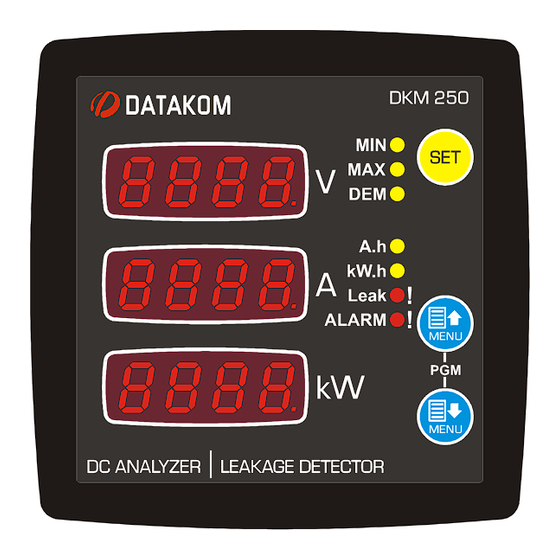
Page 5: Front And Back Panels
DKM-250 User Manual V-2.0 1.1 FRONT AND BACK PANELS... -
Page 6: Electrical Installation
DKM-250 User Manual V-2.0 1.2 ELECTRICAL INSTALLATION Do not install the unit close to high electromagnetic noise emitting devices like contactors, high current busbars, switchmode power supplies and the like. Although the unit is protected against electromagnetic disturbance, excessive disturbance can affect the operation, measurement precision and data communication quality. -
Page 7: Installation Diagram
DKM-250 User Manual V-2.0 1.3 INSTALLATION DIAGRAM... -
Page 8: Pushbutton Functions
DKM-250 User Manual V-2.0 2. PUSHBUTTON FUNCTIONS 3 front panel buttons allow navigation between measurement and programming screens. BUTTON FUNCTION If more than one active alarm exists, then display next alarm. HELD PRESSED FOR 2 SECONDS: Resets Min-Max values and alarms and displays the minimum values. -
Page 9: Screen Navigation
DKM-250 User Manual V-2.0 3. SCREEN NAVIGATION Buttons allow navigation between measurement values. The yellow led related to the currently displayed values will turn on. As an exception, if the total run hours is displayed, “Ah” and “kWh” leds will turn on. - Page 10 DKM-250 User Manual V-2.0 Display of measured current: If the measured current value is below 100A, then it is displayed with 0.01A precision. Between 100A and 1000A it is displayed with 0.1A precision. Between 1000A and 10000A it is displayed with 1A precision. When read from Modbus, the current will have 0.01A precision.
- Page 11 DKM-250 User Manual V-2.0 Alarm display: When an alarm occurs, then the ALARM led will turn on and the display will show the alarm information every 2 seconds. If multiple alarms are present, other alarms may be displayed by pressing the SET pushbutton.
- Page 12 DKM-250 User Manual V-2.0 Alarm 5 : Low Power (kW) Alarm Alarm 6 : Positive (+) earth leakage alarm Alarm 7 : Negative (-) earth leakage alarm...
-
Page 13: Programming
DKM-250 User Manual V-2.0 4. PROGRAMMING 4.1 ENTERING THE PROGRAMMING MODE In order to offer the maximum flexibility to the customer, the module has several programmable parameters. Device configurations Default screen configuration Measurement configurations Demand reset Counter reset Alarm reset... -
Page 14: Resetting Demands
DKM-250 User Manual V-2.0 4.2 RESETTING DEMANDS Parameter value 0: No operation 1: Reset demand counters Setting this parameter to 1 causes demand and max_demand values to be reset. The parameter value is not saved and always reads 0. 4.3 RESETTING ENERGY COUNTERS... -
Page 15: Resetting Run Hours
DKM-250 User Manual V-2.0 4.5 RESETTING RUN HOURS Parameter value 0: No operation 1: Reset hour counter Setting this parameter to 1 causes the run hour counter to be reset. The parameter value is not saved and always reads 0. -
Page 16: Adjusting Current Measurement Input
DKM-250 User Manual V-2.0 4.7 ADJUSTING CURRENT MEASUREMENT INPUT This parameter adjusts the rated value of the current shunt in amperes. The factory set value is 40.0A Adjustement range is between 0.1 and 3200amperes This parameter adjusts the rated voltage of the current shunt in volts. -
Page 17: Adjusting Voltage Low And High Limits
DKM-250 User Manual V-2.0 4.9 ADJUSTING VOLTAGE LOW AND HIGH LIMITS This parameter adjusts the upper limit of the high voltage alarm. If this parameter is set to 400.0 (DISB ,DISB) then high voltage is not monitored and no alarm occurs. -
Page 18: Adjusting Low And High Power Limits
DKM-250 User Manual V-2.0 4.11 ADJUSTING LOW AND HIGH POWER LIMITS This parameter adjusts the upper limit of the high power alarm. Positive and negative powers are monitored for their absolute value and the alarm occurs for any direction of the power flow. -
Page 19: Adjusting The 4-20Ma Analog Output
DKM-250 User Manual V-2.0 4.13 ADJUSTING THE 4-20mA ANALOG OUTPUT This parameter determines the analog value to be output from the 4- 20mA analog output. Factory set value is 0. Adjustment range is 0 to 22. Parameter Measurement at output... - Page 20 DKM-250 User Manual V-2.0 This parameter defines the value corresponding to 4mA current output. (low limit) Factory set value is 0. Adjustment range is between -999.9 and 3000.0 This parameter defines the value corresponding to 20mA current output. (high limit) Factory set value is 100.0.
-
Page 21: Selecting The Default Screen
DKM-250 User Manual V-2.0 4.14 SELECTING THE DEFAULT SCREEN This parameter selects the screen menu where the unit returns when no pushbutton is pressed during 5 minutes. It also determines the screen that comes when the programming mode is closed. -
Page 22: Alarm Configuration
DKM-250 User Manual V-2.0 4.15 ALARM CONFIGURATION This parameter determines the delay between an alarm condition occurs and the alarm given. Factory set value is 0. Adjustment range is 0 to 255 seconds. 0: Alarm lock disabled 1: Alarm lock enabled When this parameter is set to 1, even if the alarm cause is removed, alarms will persist until manually reset. -
Page 23: Modbus Parameters
DKM-250 User Manual V-2.0 4.16 MODBUS PARAMETERS This parameter determines the Modbus node address of the unit. Every unit in the same Modbus loop must have a different node address. Factory set value is 1. Adjustment range is 0 to 245. -
Page 24: Adjusting Low And High Earth Leakage Limits
DKM-250 User Manual V-2.0 4.17 ADJUSTING LOW AND HIGH EARTH LEAKAGE LIMITS This parameter adjusts the upper limit of the ratio of the earth voltage to supply voltage. The factory set value is 70%. Adjustment range is 0 to 100% This parameter adjusts the lower limit of the ratio of the earth voltage to supply voltage. -
Page 25: Programmable Relay Setup
DKM-250 User Manual V-2.0 4.18 PROGRAMMABLE RELAY SETUP This is the wait delay between the conditions that will activate the relay occur and the relay is activated. The factory set value is 0. Adjustment range is 0 to 255 seconds. - Page 26 DKM-250 User Manual V-2.0 Relay function is selected from below list: Value Relay function High voltage alarm Low voltage alarm High current alarm High power (kW) alarm Low power (kW) alarm Positive (+) earth leakage alarm Negative (+) earth leakage alarm...
-
Page 27: Programmable Digital Input Setup
DKM-250 User Manual V-2.0 4.19 PROGRAMMABLE DIGITAL INPUT SETUP This parameter determines the wait delay between the digital input signal and the activation of input function. The factory set value is 0. Adjustment range is 0 to 80 seconds. This parameter selects the function performed when the digital input_1 signal is active. - Page 28 DKM-250 User Manual V-2.0 Digital input functions are selected from below list: Value Function when signal is active Function when signal is passive kWh and Ah counters operate kWh and Ah counters are stopped When signal is activated, kWh and Ah...
-
Page 29: Output Pulse (Kwh, Ah, Hour) Setup
DKM-250 User Manual V-2.0 4.20 OUTPUT PULSE (kWh, Ah, hour) SETUP If any of relay functions (explained in chapter 4.17) is set to 14 (kWh, Ah or hour-run pulse), then below parameters will determine the pulse charateristics. This parameter defines the counter increment step to provide 1 pulse. -
Page 30: Displaying The Firmware Version
DKM-250 User Manual V-2.0 4.21 DISPLAYING THE FIRMWARE VERSION The firmware version is displayed in te second line of the “end end , End” screen. Any inquiry to the manufacturer must state the firmware version in question. 4.22 CALIBRATION The unit leaves the production in a calibrated status. - Page 31 DKM-250 User Manual V-2.0 In the first current input zero mode, the first display will show “1CRZ”. The second screen will display the measured instantaneous current from the input. The third display will display the offset value causing display 00.00 at no current.
- Page 32 DKM-250 User Manual V-2.0 Vin voltage is generated internally and used to check that the internal power supply is operating. In Vin calibration mode, the first display will show “vIn”. The second screen will display the measured instantaneous Vin voltage. The third...
-
Page 33: Lamp Test
DKM-250 User Manual V-2.0 4.23 LAMP TEST When programming is over, hold pressed UP and DOWN MENU buttons for 2 seconds. The unit will exit program mode and will turn on all lights for lamp testing purpose. Check that all lights are on. -
Page 34: Modbus Communications
DKM-250 User Manual V-2.0 5. MODBUS COMMUNICATIONS 5.1. DESCRIPTION The unit offers serial data communication port allowing it to be integrated in automation systems. The serial port is of RS-485 MODBUS-RTU standard. It is fully isolated from power supply and measurement terminals for failure-free operation under harsh industrial conditions. - Page 35 DKM-250 User Manual V-2.0 The checksum value in the above message may be used for the verification of checksum calculation algorithm. The normal response will be: Byte Description Value Controller address same as in the query Function code Data lenght in bytes (L)
- Page 36 DKM-250 User Manual V-2.0 Here is the sequence to write the value 0010h to the register 40h (64 decimal): 01 06 00 40 00 10 89 D2 (each byte is expressed as 2 hexadecimal characters) The checksum value in the above message may be used for the verification of checksum...
-
Page 37: Commands
DKM-250 User Manual V-2.0 Error codes Only 3 error codes are used: 01: illegal function code 02: illegal address 10: write protection (attempt to write a read_only register) Data types Each register consists of 16 bits (2 bytes) If the data type is a byte, only the low byte will contain valid data. High byte is don’t care. -
Page 38: Program Parameters
DKM-250 User Manual V-2.0 5.3. PROGRAM PARAMETERS Program parameters of the unit may be read from below registers or program parameters may be set by writing to these registers. ADRESS NAME DESCRIPTION DIMENS DATA TYPE COEFF Shunt max current Explained ch 4.7... - Page 39 DKM-250 User Manual V-2.0 ADRESS NAME DESCRIPTION DIMENS DATA TYPE COEFF Counter increment Explained ch 4.20 16 BIT 0.001 for 1 pulse unsigned word Pulse duration (sec) Explained ch 4.20 16 BIT unsigned word 0.01 Min delay between Explained ch 4.20...
-
Page 40: Measurements And Controller Records
DKM-250 User Manual V-2.0 5.4. MEASUREMENTS AND CONTROLLER RECORDS ADRESS NAME DESCRIPTION DIMENS DATA TYPE COEFF Voltage measured from 8192 32 BIT unsigned long 0.01 110V input Voltage measured from 8194 32 BIT unsigned long 0.01 60V input Voltage measured from... - Page 41 DKM-250 User Manual V-2.0 ADRESS NAME DESCRIPTION DIMENS DATA TYPE COEFF Earth leakage voltage 8248 32 BIT unsigned long 0.01 Earth leakage percent 8240 32 BIT unsigned long 0.01 8252 reserved 32 BIT unsigned long 0.01 Energy counter (kWh), 8254...
-
Page 42: Technical Specifications
Installation: Flush mounting with rear brackets Dimensions: 102x102x53mm (WxHxD) Panel Cutout: 92x92mm Weight: 200 gr EU Directives: Reference Standards: 2014/35/EC (LVD) EN 61010 (safety) 2014/30/EC (EMC) EN 61326 (EMC) DATAKOM Elektronik Ltd. Tel: +90-216-466 84 60 Fax: +90-216-364 65 65 e-mail: datakom@datakom.com.tr http: www.datakom.com.tr...
Need help?
Do you have a question about the DKM-250 and is the answer not in the manual?
Questions and answers