Table of Contents
Advertisement
Quick Links
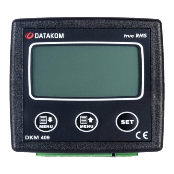
DKM-409 NETWORK ANALYSER
WITH HARMONIC MEASUREMENT AND SCOPEMETER
INTRODUCTION
The DKM-409 is a precision instrument
designed for displaying various AC
parameters in 3-phase distribution panels.
Thanks to its isolated RS-485 Modbus RTU
communication port, the device is free from
ground potential difference issues and
measured parameters are safely transferred
to factory and building automation systems.
The power supply of the unit is isolated, thus
the same device can be used in both
230/400V and 120/208V systems.
The graphic screen allows display of
waveforms and harmonic analysis graphs.
Various display screens can be scrolled
automatically. The user configurable screen
where any measured parameter set can be
displayed, transforms the unit to a custom
designed measurement panel.
J38D01
datakom@datakom.com.tr
http://www.datakom.com.tr
True RMS measurements
Harmonic distortion display ( 31 harmonics)
Oscilloscope, waveform display
Max demand display
User configurable display screen
Fully isolated RS-485 serial port
MODBUS-RTU communication
2 configurable relay outputs
Energy pulse output capability
Optically isolated, configurable digital inputs
Switched dual active-reactive power counters
Independent mains/generator energy metering
Configurable user counters
Voltage transformer ratio for MV applications
Password protected front panel programming
High visibility, 128x64 pixels graphic LCD
Reduced panel depth
Wide operating temperature range
Sealed front panel (IP54)
Plug-in connection system
- 1 -
Tel: +90-216 466 84 60
Fax: +90-216 364 65 65
FEATURES
Advertisement
Table of Contents

Related Manuals for Datakom DKM-409


Summary of Contents for Datakom DKM-409
- Page 1 Fax: +90-216 364 65 65 DKM-409 NETWORK ANALYSER WITH HARMONIC MEASUREMENT AND SCOPEMETER INTRODUCTION FEATURES The DKM-409 is a precision instrument True RMS measurements designed for displaying various AC Harmonic distortion display ( 31 harmonics) parameters in 3-phase distribution panels.
- Page 2 SAFETY NOTICE Failure to follow below instructions will result in death or serious injury • Electrical equipment should be installed only by qualified specialist. No responsibility is assured by the manufacturer or any of its subsidiaries for any consequences resulting from the non-compliance to these instructions.
-
Page 3: Table Of Contents
TABLE OF CONTENTS Section 1. INSTALLATION 1.1. FRONT / REAR PANELS 1.2. MECHANICAL INSTALLATION 1.3. ELECTRICAL INSTALLATION 1.4. CONNECTION DIAGRAM FOR 230/400V NETWORK 1.5. CONNECTION DIAGRAM FOR 120/208V NETWORK 2. PUSHBUTTON FUNCTIONS 3. DISPLAY NAVIGATION 4. DISPLAY SCREEN 4.1. DISPLAY SCREEN DETAILS 4.2. -
Page 4: Installation
1. INSTALLATION Before installation: • Read the user manual carefully, determine the correct connection diagram. • Remove all connectors and mounting brackets from the unit, then pass the unit through the mounting opening. • Put mounting brackets and tighten. Do not tighten too much, this can brake the enclosure. -
Page 5: Front / Rear Panels
1.1 FRONT / REAR PANELS 1.2 MECHANICAL INSTALLATION Panel Cutout Required Panel Depth J38D01 - 5 -... -
Page 6: Electrical Installation
1.3 ELECTRICAL INSTALLATION Do not install the unit close to high electromagnetic noise emitting devices like contactors, high current busbars, switchmode power supplies and the like. Although the unit is protected against electromagnetic disturbance, excessive disturbance can affect the operation, measurement precision and data communication quality. •... -
Page 7: Connection Diagram For 230/400V Network
1.4 CONNECTION DIAGRAM FOR 230/400V NETWORK J38D01 - 7 -... -
Page 8: Connection Diagram For 120/208V Network
1.5 CONNECTION DIAGRAM FOR 120/208V NETWORK J38D01 - 8 -... -
Page 9: Pushbutton Functions
2. PUSHBUTTON FUNCTIONS Three buttons on the front panel provide access to configuration and measurement screens. BUTTON FUNCTION Previous screen Decrease related value (configuration mode) Next screen Increase related value (configuration mode) Changes voltage and current channels for • scopemeter display •... -
Page 10: Display Navigation
3. DISPLAY NAVIGATION J38D01 - 10 -... -
Page 11: Display Screen
4. DISPLAY SCREEN 4.1 DISPLAY SCREEN DETAILS Display 1 Display 2 Display 3 DATAKOM LOGO U1-2 (V) V1-N (V) Software version U2-3 (V) V2-N (V) U3-1 (V) V3-N (V) Frequency (Hz) Frequency (Hz) Display 4 Display 5 Display 6 I1 (A) -
Page 12: Phase Sequence Display
4.2 PHASE SEQUENCE DISPLAY The unit checks continuously the sequence of AC phase voltages. If voltages are in the correct sequence, below symbol appears on voltage display pages, namely pages 2 and 3 If voltages are in wrong order, the symbol disappears. The effect of phase sequence failure is configurable. -
Page 13: Display Symbols
5. DISPLAY SYMBOLS SYMBOL DESCRIPTION Software version Phase 1 to phase 2 AC RMS voltage value Phase 2 to phase 3 AC RMS voltage value Phase 3 to phase 1 AC RMS voltage value Frequency value Phase 1 to Neutral AC RMS voltage value Phase 2 to Neutral AC RMS voltage value Phase 3 to Neutral AC RMS voltage value Phase 1 AC RMS current value... -
Page 14: Setting Auto-Scroll Mode
6. SETTING AUTO-SCROLL MODE The unit offers the possibility of automatically scanning of all display screens. In order to enable auto-scroll function hold the SET button pressed for 3 seconds. In order to disable auto-scroll function hold the SET button pressed for 3 seconds. When the auto-scroll is enabled, the unit will switch to the next screen every 5 seconds. -
Page 15: Device Configuration
8. DEVICE CONFIGURATION 8.1 INTRODUCTION In order to offer the maximum flexibility to the user, the unit has several configurable parameters. • Device configurations • Line Configurations LCD Contrast Clearing Counters Language selection Resetting demand values Modbus node address Overcurrent configuration User display screen Setting the current transformer ratio configuration... -
Page 16: Adjusting The Lcd Contrast
8.2 ADJUSTING THE LCD CONTRAST Select “LCD CONTRAST” on “CONFIGURATION MENU”. Change the contrast value with until best visibility is obtained and then press to save new LCD contrast value and return back to “CONFIGURATION MENU”. 8.3 LANGUAGE SELECTION Select “LANGUAGE” on “CONFIGURATION MENU”. -
Page 17: Voltage Transformer Ratio
8.5 VOLTAGE TRANSFORMER RATIO If a voltage transformer is used, then its ratio needs to be set to the unit. The voltage transformer ratio is defined as primary voltage / secondary voltage. The secondary is always supposed 1.0. Thus only the primary is programmed. -
Page 18: Modifying The Serial Number
8.8 MODIFYING THE SERIAL NUMBER The unit holds a user definable 16 characters serial number. Every character can take values between 0-9 and A-Z. The default value of serial number is “0000000000000000”. Select “SERIAL NUMBER” on “CONFIGURATION MENU”. Write new serial number with MENU buttons. -
Page 19: Configuring An Item's Low Or High Limit
8.10 CONFIGURING AN ITEM’S LOW OR HIGH LIMIT Select “REFERENCE CNFG” on “CONFIGURATION MENU”. Select low limit (minimum acceptable value) or high limit (maximum acceptable value) of the item to configure then press Then select the item to configure on the list and press again. - Page 20 After entering the limit value of the item, the action to be taken when the condition occurs has to be selected. LOCK means that, once the condition occurs, it will persist until manually reset by the user. Otherwise the condition will reset automatically when the event causing the condition goes off.
-
Page 21: Input Configuration
2.11 INPUT CONFIGURATION The unit has two configurable inputs. Level transitions from high to low (NC=normally closed contact) and low to high (NO=normally open contact) may be programmed independently. There are various functions that can be assigned for each input. Some of these actions can be clearing a counter, selecting between counters, clearing fault conditions, assigning the input to relay input registers. -
Page 22: Relay Configuration
2.12 RELAY CONFIGURATION • Relay = VALUE 1 NOR VALUE 2: If at The unit has 2 relay outputs with least one of value registers is TRUE then configurable functions. the relay contact will open. Otherwise it Relays can be configured as kW or kVAr will close. -
Page 23: Resetting A Counter
A “delay before response can be set for relays. The screen below will be displayed after first two steps. Set the required delay time here. 2.13 RESETTING A COUNTER The unit offers 2 sets of active and reactive power counters together with 4 user counters. Counters can be reset via the configuration menu whenever required. -
Page 24: Overcurrent Detector Configuration
2.15 OVERCURRENT DETECTOR CONFIGURATION The “OVERCURRENT” function is used in order to generate a protection relay output when any of the phase currents exceeds the preset value for “TIMEOUT” duration. The response time depends on the overcurrent rate as shown on below graph. OVERCURRENT AREA PERMITTED AREA A: Over current value... -
Page 25: Phase Sequence Failure
2.16 PHASE SEQUENCE FAILURE The unit checks continuously the sequence of AC phase voltages. If voltages are in the correct sequence, below symbol appears on voltage display pages, namely pages 2 and 3. If voltages are in wrong order, the symbol disappears. -
Page 26: Return To Factory Settings
2.18 RETURN TO FACTORY SETTINGS It is possible to reset the unit to factory settings, before starting a new configuration process. For this select “RETURN FACTORY” on “CONFIGURATION MENU”. Then select “YES” and press to reset the unit to factory configuration and return to “CONFIGURATION MENU”. -
Page 27: Modbus Communications
9. MODBUS COMMUNICATIONS 9.1 DESCRIPTION The unit offers serial data communication port allowing it to be integrated in automation systems. The serial port is of RS-485 MODBUS-RTU standard. It is fully isolated from power supply and measurement terminals for failure-free operation under harsh industrial conditions. The MODBUS properties of the unit are: -Data transfer mode: RTU -Serial data: 9600 bps, 8 bit data, no parity, 1 bit stop... - Page 28 The normal response will be: Byte Description Value Controller address same as in the query Function code Data lenght in bytes (L) number of registers * 2 High byte of 1st register Low byte of 1st register High byte of 2nd register Low byte of 2nd register ..
- Page 29 Here is the sequence to write the value 0010h to the register 40h (64 decimal): 01 06 00 40 00 10 89 D2 (each byte is expressed as 2 hexadecimal characters) The checksum value in the above message may be used for the verification of checksum calculation algorithm The normal response will be the same as the query: Byte...
-
Page 30: Modbus Registers
Error codes Only 3 error codes are used: 01: illegal function code 02: illegal address 10: write protection (attempt to write a read_only register) Data types Each register consists of 16 bits (2 bytes) If the data type is a byte, only the low byte will contain valid data. High byte is don’t care. For data type longer than 16 bits, consecutive registers are used. - Page 31 ADDRE NAME DESCRIPTION LENGTH R/W TYPE 40023 V1 phase to neutral voltage AC RMS V1 RMS 32 BIT R-O unsigned long value 40024 40025 V2 phase to neutral voltage AC RMS V2 RMS 32 BIT R-O unsigned long value 40026 40027 V3 phase to neutral voltage AC RMS V3 RMS...
- Page 32 ADDRE NAME DESCRIPTION LENGTH R/W TYPE 40060 40061 ∑P Active Total active power (kW) 32 BIT R-O signed long Power 40062 40063 ∑Q Reactive Total reactive power (kW) 32 BIT R-O signed long Power 40064 0.00 40065 Cosф 1 Phase 1 power factor 16 BIT R-O signed word 0.00...
-
Page 33: Warning Registers
9.3 WARNING REGISTERS MODBUS warnings register section contains 5 x 16 bit registers, 80 bits in total. First 40 bits indicate values below set limit, last 40 bits indicate values above set limits. REG. TOTAL ADDRESS DESCRIPTION 40018 V1 RMS value below the set value V2 RMS value below the set value V3 RMS value below the set value I1 RMS value below the set value... - Page 34 REG. TOTAL ADDRESS DESCRIPTION 40020 User counter 3 below the set value User counter 4 below the set value Reserved Reserved Reserved Reserved Reserved Reserved V1 RMS value above the set value V2 RMS value above the set value V3 RMS value above the set value I1 RMS value above the set value I2 RMS value above the set value I3 RMS value above the set value...
- Page 35 REG. TOTAL ADDRESS DESCRIPTION 40022 Total power factor above the set value Frequency above the set value Active power counter 1 above the set value Reactive power counter 1 above the set value Active power counter 2 above the set value Reactive power counter 2 above the set value User counter 1 above the set value User counter 2 above the set value...
-
Page 36: Technical Specifications
10. TECHNICAL SPECIFICATIONS Power Supply Input: 170 - 275VAC, 50 - 60Hz nominal (± 10%) Different AC supply voltages available. Measurement Input Range: Voltage inputs: 10 - 300 V AC (L-N) 20 - 520 V AC (L-L) Current inputs: 0.2 – 5.5 A AC Frequency: 30 - 100 Hz Accuracy:...
Need help?
Do you have a question about the DKM-409 and is the answer not in the manual?
Questions and answers