
Related Manuals for Retsch SM200


Summary of Contents for Retsch SM200
- Page 1 Manual Cutting Mill SM200 Translation © Retsch GmbH, 42781 Haan, Retsch-Allee 1-5, Germany | 14.01.2019 Version 0005...
- Page 2 Copyright © Copyright by Retsch GmbH Retsch-Allee 1-5 42781 Haan Germany...
-
Page 3: Table Of Contents
Table of Contents Notes on the Manual ........................5 Explanations of the Safety Instructions ..................6 General Safety Instructions ......................7 Repairs ............................8 Confirmation ............................ 9 Packaging, Transport and Installation ..................10 Packaging ..........................10 Transport ............................ 10 Temperature fluctuations and condensed water ................10 Conditions for the Installation Site .................... - Page 4 Notes on the Manual...
-
Page 5: Notes On The Manual
This operating manual does not contain any repair instructions. If faults arise or repairs are necessary, please contact your supplier or get in touch with Retsch GmbH directly. Application technology information relating to samples to be processed is not included but can be read on the Internet on the respective device’s page at www.retsch.com. -
Page 6: Explanations Of The Safety Instructions
Notes on the Manual 1.1 Explanations of the Safety Instructions In this Operating Manual we give you the following safety warnings Serious injury may result from failing to heed these safety warnings. We give you the following warnings and corresponding content. WARNING Type of danger / personal injury Source of danger... -
Page 7: General Safety Instructions
All persons concerned with the machine in any form This machine is a modern, high performance product from Retsch GmbH and complies with the state of the art. Operational safety is given if the machine is handled for the intended purpose and attention is given to this technical documentation. -
Page 8: Repairs
Notes on the Manual 1.3 Repairs This operating manual does not contain any repair instructions. For your own safety, repairs may only be carried out by Retsch GmbH or an authorized representative or by Retsch service engineers. In that case please inform:... -
Page 9: Confirmation
Confirmation Be s t ä t i g u n g Confirmation This operating manual contains essential instructions for operating and maintaining the device which must be strictly observed. It is essential that they be read by the operator and by the qualified staff responsible for the device before the device is commissioned. -
Page 10: Packaging, Transport And Installation
Packaging, Transport and Installation Packaging, Transport and Installation 3.1 Packaging The packaging has been adapted to the mode of transport. It complies with the generally applicable packaging guidelines. NOTICE Storage of packaging – In the event of a complaint or return, your warranty claims may be endangered if the packaging is inadequate or the machine has not been secured correctly. -
Page 11: Electrical Connection
Packaging, Transport and Installation NOTICE Atmospheric humidity – Electronic and mechanical components may be damaged and the performance data alter to an unknown extent. • Do not exceed the admissible range for atmospheric humidity. 3.5 Electrical Connection WARNING When connecting the power cable to the mains supply, use an external fusethat complies with the regulations applicable to the place of installation . -
Page 12: Type Plate Description
Packaging, Transport and Installation 3.6 Type Plate Description Fig. 1: Type plate lettering 1 Device designation 2 Year of production 3 Part number 4 Serial number 5 Manufacturer’s address 6 CE marking 7 Disposal label 8 Bar code 9 Power version 10 Mains frequency 11 Capacity 12 Amperage... -
Page 13: Removing The Transportation Aid
Packaging, Transport and Installation 3.7 Removing the Transportation Aid Fig. 2: Removing the transport aid Lift the device only by the transport aid (TH). The weight of the device is approx. 90 kg. Choose a safe lifting sling that is approved for this weight. Keep the eye bolt(TH) for transport again at a later date. -
Page 14: Mounting The Feed Hopper
Packaging, Transport and Installation 3.8 Mounting the Feed Hopper WARNING 1.W0004 Risk of injury to skin and hands Fast rotating cutting blade – There is a risk of injuring hands, fingers and skin. • Never operate the device without a feed hopper. NOTICE Transport safeguard –... -
Page 15: Mounting The Feed Hopper
Packaging, Transport and Installation 3.8.2 Mounting the Feed Hopper Fig. 4: Mounting the feed hopper • Push the handle of the door latch (F) backwards. • Open the grinding chamber door (T). • Pull the plunger (B) into the upper latching position. •... -
Page 16: Installation Of The Device
Packaging, Transport and Installation Fig. 5: Putting on the protective caps NOTE When new, the grinding chamber door and the handle on the door latch are somewhat difficult to move. 3.9 Installation of the Device Installation height: maximum 2000 m above sea level NOTE Installation –... -
Page 17: Height Adjustment And Alignment Of The Support Structure
Packaging, Transport and Installation 3.10 Height adjustment and alignment of the support structure The height of two wheels on the support structure can be changed to compensate for an uneven surface and for the optimal alignment of the machine. Fig. 6: Adjusting the height of the support structure Designation Locking pin Adjusting nut... - Page 18 Packaging, Transport and Installation When aligning the support structure, a backwards tilt of approx. 1-2° is recommended for an ideal operating function. We recommend using a spirit level to check the ideal incline of the support structure. 1 – 2° backwards tilt Back wheels Front wheels...
-
Page 19: Technical Data
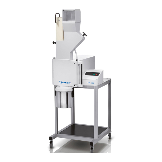
Technical Data Technical Data 4.1 Use of the Device for the Intended Purpose Target group: Owners/managing operators, operators Machine type designation: SM 200 This heavy-duty cutting mill serves to grind flexible, hard-ductile and fibrous products and product mixtures in batches or continuously. It is fundamentally not designed for grinding wet or moist materials. -
Page 20: Emissions
Technical Data 4.2 Emissions CAUTION Damage to hearing The level of noise can be high depending on the type of material, the knife used, the speed set and the duration of the grinding process. - Noise that is excessive in terms of level and duration can cause impaired or permanently damaged hearing. -
Page 21: Required Floor Space
Technical Data Fig. 8: Dimensions 4.8 Required Floor Space 1090 mm x 760 mm – no safety gaps necessary... -
Page 22: Operating The Device
Operating the Device Operating the Device 5.1 Views of the Instrument Fig. 9: Front view... - Page 23 Operating the Device Fig. 10: Front view from the left (detail) Fig. 11: Rear view...
- Page 24 Operating the Device Fig. 12: View of the grinding chamber...
-
Page 25: Overview Table Of The Parts Of The Device
Operating the Device 5.2 Overview table of the parts of the device Description Function Element Feed hopper access barrier Prevents people reaching into the feed hopper Plunger When pulled, it releases the material feed chute. Pushes sample onto the rotor. Metering plunger Pushes the material to be ground into the feed hopper area of the filling plunger... -
Page 26: Operating Elements And Displays
Operating the Device 5.3 Operating elements and displays Fig. 13: View of the control panel and the display 5.4 Overview Table of the Operating Elements and the Display Description Function Element Start button Starts the device Stop button Stops the device Green LED Device is on Red LED... -
Page 27: Opening And Closing Of The Device
Operating the Device 5.5 Opening and Closing of the Device The motor must come to a complete stop before the mill housing can be opened. • Stop the device by pressing the stop button (G6). • Pull the mini detent pin (E) upwards •... -
Page 28: Removing The Rotor
Operating the Device NOTE Wear or damage of the device Operation without grinding set − During operation of the device without grinding set, excessive wear or damage to the device may occur. • Operate the device only with a grinding set mounted. NOTE Damage to mechanical components Blockages typical of cutting mills... -
Page 29: Inserting The Filter Unit And Collecting Receptacle
Operating the Device 5.8 Inserting the filter unit and collecting receptacle The filter unit serves as an air outlet for the air flow generated by the comminuting rotors. Fig. 16: Mounting and removing the filter unit • As shown in the illustration, insert the bayonet fixing(BV) that is on the filter unit (J) into the discharge flange(AV). -
Page 30: Stopping The Grinding Process
Operating the Device 5.10 Stopping the grinding process The grinding process can be interrupted by pressing the stop button (G6). Once the motor has stopped, you can pull the mini detent pin (E) upwards and press the handle on the door latch (F) backwards. The grinding chamber door can be opened now. -
Page 31: Mode Of Operation Of Feed Hopper
Mode of Operation of Feed Hopper Mode of Operation of Feed Hopper NOTE Motor blockage The material being ground clogs the rotor – Blockages can damage mechanical components. • Feed material only while the device is running. • Dose the material feed to suit the properties of the material. •... -
Page 32: Assembling And Using The Cyclone
Assembling and using the cyclone Assembling and using the cyclone 7.1 Cyclone assembly CAUTION V0014 Injuries to limbs Rotating blade – Can cause injury to hands and feet. • Keep hands and feet away from the device openings when the device is switched on. •... - Page 33 Assembling and using the cyclone Fig. 19: Fastening the discharge flange • Insert the retrofit dust removal (U). • Tighten the screw (U1). Fig. 20: Inserting the plug for the sliding block • Insert the plug (HS) into the back (flat surface) of the sliding block (NS). Fig.
- Page 34 Assembling and using the cyclone Fig. 22: Turning the sliding block • Push in the sliding block against the resistance of the plug and turn the sliding block to the position indicated. • Insert the second sliding block in the same way. Fig.
- Page 35 Assembling and using the cyclone Fig. 25: Assembled cyclone CAUTION Before using the industrial vacuum cleaning, read the operating instructions supplied with the vacuum cleaner. Fig. 26: Connecting the industrial vacuum cleaner • Plug the connector for dust extraction (W1) into the top opening on the cyclone.
-
Page 36: Inserting The Wide Mouth Bottle Adapter
Assembling and using the cyclone 7.1.1 Inserting the wide mouth bottle adapter Fig. 27: Inserting the wide mouth bottle adapter • Insert the adapter for wide mouth bottles (Z5) into the outlet opening of the cyclone (AZ) . • Affix the adapter using the threaded pin (GS). •... -
Page 37: Cleaning And Service
Cleaning and service Cleaning and service 8.1 Adjusting the cutting bars To ensure that the device will function satisfactorily, it is necessary to check the cutting gap (target spacing 0.3 mm). The (SL) cutting bars are therefore moveable so that the cutting gap can be set. - Page 38 Cleaning and service Fig. 29: Twist the rotor until it rotates freely Minimum. 0.3mm Fig. 30: Setting the cutting gaps • Use a (BL) feeler gauge to check the cutting gap between all three (SL) cutting bars. The gap should be at least 0.3 mm. The (BL) feeler gauge must be put on the two cutting surfaces as shown in the illustration.
- Page 39 Cleaning and service • Tighten the (WS) screw and check the cutting gap. Repeat the procedure if necessary. • Tighten the (W) screw at 7Nm again after adjusting the cutting bar. • Then mount the right and left covers onto the device again. NOTE Do not set the cutting gap at less than 0.3 mm.
-
Page 40: Fault Messages
Fault messages Fault messages Flashing sequence Meaning Instruction • Close the door. G4 and G5 flash Safety circuit is not • alternately Pull the locking bracket forwards. closed • Allow the locking bolt to engage. • Remove the blocking pieces of sample material G5 flashes Motor block from the grinding chamber. -
Page 41: Disposal
Disposal 10 Disposal Please observe the respective statutory requirements with respect to disposal. Information on disposal of electrical and electronic machines in the European Community. Within the European Community the disposal of electrically operated devices is regulated by national provisions that are based on the EU Directive 2002/96/EC on Waste Electrical and Electronic Equipment (WEEE). -
Page 42: Index
Index 11 Index flash..............38 flashing .............38 2200 W .............19 Flashing sequence ..........38 Flashing sequence during error message ..38 Frequency of use ..........26 Access to the cutting bars .........35 Front view ............20 Adjusting the cutting bars ........35 Front view from the left (detail) ......21 Adjusting the height of the support structure ..15 Function............ - Page 43 Index Optimal alignment ..........16 Service Address ..........8 Overview Table of the Operating Elements and Setting the cutting gaps ........36 the Display ............24 Sliding block .............31 Overview table of the parts of the device ...23 Starting the grinding process ......27 Stopping the grinding process ......27 Packaging ............10 Part number ............11 Target group ............7...
- Page 46 Copyright © Copyright by Retsch GmbH Retsch-Allee 1-5 42781 Haan Germany...
Need help?
Do you have a question about the SM200 and is the answer not in the manual?
Questions and answers