Advertisement
Quick Links
EVERLAST
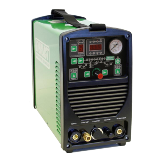
50 Amp Digital IGBT TIG/Stick/Plasma Cutter
CC
DC
GTAW-P
SMAW
PAC
IGBT
1
~
PHASE
DV
120/240V
everlastwelders.com
ULTRA-ARC 205
Operator's Manual for the Ultra-Arc 205
Safety, Setup and General Use Guide
1-877-755-9353
329 Littlefield Ave. South San Francisco, CA
Rev. 1
Specifications and Accessories subject to change without notice.
94080 USA
0 000226-20
Advertisement

Subscribe to Our Youtube Channel
Related Manuals for Everlast ULTRA-ARC 205


Summary of Contents for Everlast ULTRA-ARC 205
- Page 1 ULTRA-ARC 205 50 Amp Digital IGBT TIG/Stick/Plasma Cutter GTAW-P SMAW IGBT PHASE 120/240V Operator’s Manual for the Ultra-Arc 205 Safety, Setup and General Use Guide Rev. 1 0 000226-20 everlastwelders.com Specifications and Accessories subject to change without notice. 1-877-755-9353 329 Littlefield Ave. South San Francisco, CA...
- Page 2 The owner of this product assumes all liability for its use and maintenance. Everlast Power Equipment INC. does not warrant this prod- uct or this document for fitness for any particular purpose, for performance/accuracy or for suitability of application. Furthermore, Everlast Power Equipment INC.
- Page 3 Your unit registration is important should any information such as product updates or recalls be issued. It is also important so that we may track your satisfaction with Everlast products and services. If you are unable to register by website, contact Everlast directly through the sales department via the main cus- tomer service number in your country/region.
- Page 4 Date of Purchase___________________________ Everlast USA: Everlast consumer satisfaction email: sales@everlastwelders.com Everlast Website: everlastwelders.com Everlast Technical Support: tech@everlastwelders.com Everlast Welding Support: performance@everlastwelders.com Everlast Support Forum: http://www.everlastgenerators.com/forums/ index.php Main toll free number: 1-877-755 WELD (9353) 9am—5pm PST M-F FAX: 1-650-588-8817 Everlast Canada: Everlast consumer satisfaction email: sales@everlastwelders.ca...
- Page 5 Safety Precautions Everlast is dedicated to providing you with the best possible equipment and service to meet the de- manding job requirements that you may have. We want to go beyond delivering a satisfactory prod- uct to you. That is the reason we offer free technical and basic welding support to assist you with your needs, should an occasion occur where it is needed.
- Page 6 Safety Precautions These safety precautions are for protection of safety and health. Failure to follow these guidelines may result in serious injury or death. Be careful to read and follow all cautions and warnings. Protect yourself and others. Welding and cutting processes produce high levels of ultraviolet (UV) radiation that can cause severe skin burn and damage.
- Page 7 Safety Precautions WARNING! Persons with pacemakers should not weld, cut or be in the welding area until they consult with their physician. Some pacemakers are sensitive to EMF radiation and could severely malfunction while welding or while being in the vicinity of someone welding. Serious injury or death may occur! Welding and plasma cutting processes generate electro-magnetic fields and radiation.
- Page 8 Safety Precautions WARNING! Electrical shock can kill. Make sure all electrical equipment is properly grounded. Do not use frayed, cut or otherwise damaged cables and leads. Do not stand, lean or rest on ground clamp. Do not stand in water or damp areas while welding or cutting.
- Page 9 Everlast. Various diameter consumables for lower amp use are available. The unit comes with a spare 30 Amp glass-type (slow-blow) fuse for the pilot arc. Set this fuse aside where you can find it. Replacement fuses may be bought locally (use part number printed on fuse for reference) or directly from Everlast.
- Page 10 Section 1 Introduction and Specifications ULTRA-ARC 205 Specifications Inverter Type Digital IGBT (DC Output only) Memory Settings Up to 9 possible memory slots Minimum/Maximum Rated Output TIG 120V: 5A/10.2V-125A/15V 240V: 5A/10.2V-200A/18V Minimum/Maximum Rated Output Stick 120V: 5A/20.2V-100A/24V 240V: 5A/20.2V-160A/26.4V Minimum/Maximum Rated Output Plasma...
- Page 11 GENERAL PRODUCT INFORMATION: The Ultra-Arc 205 utilizes the latest in digital inverter design technology. This new design is an improvement over its predecessor, the PowerUltra 205Pi. This unit redesign has incorporated more advanced Stick and TIG welding features and even now includes a memory function with up to 9 memory slots to preserve favorite settings.
- Page 12 This unit may be run on a generator capable of 7500 Surge Watts. Additionally, the generator must provide “clean power”. Clean power is de- fined as having 5% or less Total Harmonic Distortion (THD). This is a rating given by the manufacturer of the generator, and not Everlast. This is similar to the power normally supplied at a wall outlet.
- Page 13 Section 2 Quick Setup Guide TIG Connections: Front View of TIG Torch and Work Clamp PILOT ARC TORCH CONTROL WORK PIECE IMPORTANT: The foot pedal and the torch switch cannot be connected at the same time.
- Page 14 Section 2 Quick Setup Guide Stick Connections: Front View of Electrode Holder and Work Clamp PILOT ARC CONTROL TORCH WORK PIECE NOTICE: The stick function will require you to move the torch to the work piece setting for DCEP+ (Reverse Polarity). In this case, ignore the marking and remember the left terminal is negative and the right terminal is positive.
- Page 15 Section 2 Quick Setup Guide Plasma Connections: Front View of Plasma Torch and Work Clamp TORCH CONTROL PILOT ARC WORK PIECE IMPORTANT: Avoid firing the torch unless you are ready to cut. Excessive firing without cutting will wear the consumables at an accelerated rate.
- Page 16 These are available almost anywhere welding supplies Minute (LPM) are sold, both locally and online. NOTICE: TIG shielding gas must be 100% argon or Ar/He mix. If using Ar/He, never exceed 25% Helium. Never use CO2 or Ar/CO2 or other Ar mixes. EVERLAST...
- Page 17 Section 2 Quick Setup Guide Plasma Connections: Compressor and Dryer Diagram To adjust air pressure: Select purge button. Then, Pull up on top slightly until click is heard to adjust. Push top back down to lock air pressure.. Deselect purge. Fittings (Push to Connect and 5/8”...
- Page 18 Section 2 Quick Setup Guide STOP! To set the air pressure or TIG torch Gas Flow Rate, use the “PURGE” feature to initiate air flow, then adjust the pressure while air is continually flowing. Do not fire the torch to initiate air or shielding gas flow. Firing the Plasma torch without cutting significantly increases consumable wear.
- Page 19 Section 2 Quick Setup Guide TERM DEFINITION AND EXPLANATION OF WELDING FEATURES AND TERMS 2T/4T In 2T or 4T modes, the torch switch is used to start and control the weld cycle. Simply put, in 2T mode, the torch switch is simply pressed and held down to start the arc and begin welding.
- Page 20 Section 2 Quick Setup Guide TERM DEFINITION AND EXPLANATION OF WELDING FEATURES AND TERMS High Frequency Start This refers to the type of start in TIG mode. High Frequency (HF) provides an intense HF impulse from the internal HF board and point gap that jumps the gap between the Tip of the Tungsten and the Work Piece.
- Page 21 Section 2 Quick Setup Guide Front Panel Controls ITEM DESCRIPTION Memory. If you intend to save a program, press select to toggle to the desired number where you wish to save a program before you attempt setup. Make desired adjustments to program parameters. Once completed, press and hold the select/save button for 3 seconds to save the program. Once the program has saved, the “SAVE”...
- Page 22 Switch. This switch serves as the main power switch for the unit. If a severe fault or short takes place, this breaker switch will trip. If the breaker trips, find and rectify fault before attempting to power the unit back on. If the switch does not reset, contact Everlast.
- Page 23 Section 3 Operation Besides a butt joint and lap joint which are often used for V-GROOVE (60-80°) DOUBLE V-GROOVE thinner metal gauges, consider using one of these groove joints for best welding results. When grinding or cutting the bevels, especially with a single V-groove, it may be beneficial to leave a small land with a gap between the joint to achieve U-GROOVE DOUBLE U-GROOVE...
- Page 24 Section 3 Operation Basic TIG Operation General Setup. The process to set up the welder for the the tip of the Tungsten and the weld puddle. As your skill basic TIG mode with a foot pedal is as simple as plugging progresses, you will want to add filler wire to your practice.
- Page 25 Section 3 Operation Basic TIG Operation TIG Pulse. The TIG pulse creates two amp values, a high starts to melt before you dip, you have it too close, or you and a low value that cycle back and forth between each have the rod inclined too much so that heat is being di- other while welding.
- Page 26 Section 3 Operation Basic TIG Operation EXAMPLE 1 Peak Pulse Amps: 100 amps, Base Amps: 50% Pulse Time On: 50% AMPS DC Pulse Frequency: 1 Hz Pulse Time ON Welding Amps Pulse Amps Pulse Hz EXAMPLE 2 Peak Pulse Amps: 100 amps Base Amps: 65% AMPS Pulse Time On : 65%...
- Page 27 TIG ARC STARTING Section 3 Operation LIFT START OPERATION NOTICE: When using the TIG lift start function, the lift start should be performed using a light touch and a quick, seamless motion. Lift Start with a remote is often used anywhere HF use is restricted, particularly in hospitals, or where computers are in close proximity. Steel or Stainless are good candidates for Lift Start operation.
- Page 28 Section 3 Operation TUNGSTEN SHARPENING •Use a dedicated grinding wheel or contamination may result. Do not breath grinding dust! Wear eye protection and gloves. •Grip the Tungsten firmly. •Grind the Tungsten perpendicular to the wheel face. Allow tungsten to grind slowly without much pressure. •Rotate the Tungsten quickly as it is being ground to keep the point even and symmetrical.
- Page 29 Section 3 Operation STICK ARC STRIKING METHODS 1.Make sure the unit is turned on and the boot cycle has finished. 2.Select the Stick Process on the Selector. 3.Make sure the electrode holder is in the Positive connector and the work clamp is in the negative connector. 4.Select the Amp level desired.
- Page 30 Section 3 Operation NOTICE: The design of the blow back start may cause a slight delay in the arc as the air pressure must built inside the torch tubing and head to create the pressure needed to force the electrode off the nozzle seat. This may take up to a second, especially when using longer torches or marginal air supply systems.
- Page 31 When stepping down amps to cut thinner material, you must change to smaller orifice nozzle. Nozzles are offered in different sizes which are made for different amp levels. See the torch parts page for amp range and size of consumables. Everlast offers OEM size and configuration of consumables originally supplied with the torch for replacements and do not offer all configurations or sizes.
- Page 32 Section 3 Operation RESULTS OF CUT AT CORRECT SPEED, RESULTS OF CUT AT FAST SPEED AIR PRESSURE AND TORCH ANGLE ROUGH, DISTINCT CUT LINES SPACED FAR APART SMOOTH, EVEN CUT LINES WITH A S REARWARD SWEEP NOTICEABLE SMALL, HARD DROSS MINIMAL EASY TO CLEAN DROSS RESULTS OF TOO MUCH CURRENT RESULTS OF CUT AT SLOW SPEED...
- Page 33 Section 3 Operation AN EXAMPLE OF CUTTING A LEAD-IN WHEN CUTTING OUT A DISK SHAPED OBJECT AN EXAMPLE OF CUTTING A LEAD-IN WHEN CUTTING HOLE IN AN OBJECT NOTICE: When cutting an object, particularly a pattern shape, where the torch must pierce or re-fire in-line at an intersection of a cut, a lead -in cut should be employed.
- Page 34 Section 3 Operation Description Order OEM p/n BW S-45 Complete Torch G1/4 5M 33013101 BW S-45 Complete Torch M16x1.5 5M 33013102 BW S-45 Complete Torch M14x1.5 5M 33013103 BW S-45 Complete Torch M14x1 5M 33013104 BW S-45 Complete Torch Central Adaptor 5M 33013105 BW S-45 Torch Head 3302270...
- Page 35 Section 3 Operation EXPANDED VIEW OF TIG TORCH (Actual appearance may vary slightly from what is listed.) 5/8” TYPICAL PARTS FOR Air-Cooled 26 Series Torch ( STYLE MAY VARY) QTY. Long Back Cap with O-Ring Short Back Cap Opt. Torch Head Insulator Collet 1/16 or 3/32 Collet Holder...
- Page 36 Eliminate drafts. Check if there is sufficient shielding gas left in tank. Check gas flow. Adjust for higher flow of gas. Listen for audible click of gas solenoid. If no click is heard, then contact Everlast Support. Clean weld properly, especially in Aluminum. Too short of post flow. Check tungsten stick out.
- Page 37 NOTICE: Although point gap adjustment is usually considered a part of regular maintenance, and is not an item covered by warranty, the following adjustment process is intended for experienced users only. If you suspect you have a problem with the point gap due to hard starting of the arc, contact Everlast Tech Support before proceeding with point gap adjustment for proper diagnosis and a more detailed adjustment procedure.
- Page 38 Machine runs. Torch switch wire is loose. Problem with Central connector. Torch is not properly connected. IGBT or PCB bad, contact Everlast. Over current/Duty cycle Error Code. Machine runs, but no output. Duty cycle exceeded or Over current. Allow machine to cool. Reset main power switch after full cool down period.
- Page 39 Section 3 Troubleshooting Having trouble setting up your unit for best cutting? Try the following: Keep your standoff to less than 1/8” distance from the work piece. • Always use dry air. Drain compressor daily to improve effectiveness of air dryers and to prevent •...
Need help?
Do you have a question about the ULTRA-ARC 205 and is the answer not in the manual?
Questions and answers