
Related Manuals for KROHNE OPTISYS TUR 1050


Summary of Contents for KROHNE OPTISYS TUR 1050
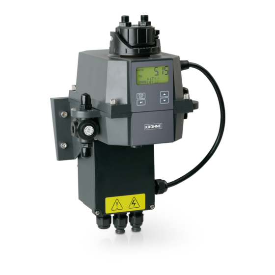
- Page 1 OPTISYS TUR 1050 OPTISYS TUR 1050 OPTISYS TUR 1050 OPTISYS TUR 1050 Handbook Handbook Handbook Handbook Compact measuring system for turbidity © KROHNE 02/2017 - 4002444302 - MA OPTISYS TUR 1050 R03 en...
- Page 2 All rights reserved. It is prohibited to reproduce this documentation, or any part thereof, without the prior written authorisation of KROHNE Messtechnik GmbH. Subject to change without notice. Copyright 2017 by KROHNE Messtechnik GmbH - Ludwig-Krohne-Str. 5 - 47058 Duisburg (Germany) www.krohne.com 02/2017 - 4002444302 - MA OPTISYS TUR 1050 R03 en...
-
Page 3: Table Of Contents
4.5.1 Connecting the cables in the junction box power assembly ..........24 4.5.2 Alarms terminal (signal output) ................... 25 4.5.3 RS 485 or 4...20 mA signal output..................25 4.5.4 Connecting the sensor interconnect cable................26 02/2017 - 4002444302 - MA OPTISYS TUR 1050 R03 en www.krohne.com... - Page 4 6.6.2 Form (for copying) to accompany a returned device............54 6.7 Disposal .......................... 54 7 Technical data 7.1 Measuring principle......................55 7.2 Technical data table ....................... 56 7.3 Dimensions and weight ....................58 8 Notes www.krohne.com 02/2017 - 4002444302 - MA OPTISYS TUR 1050 R03 en...
-
Page 5: Safety Instructions
OPTISYS TUR 1050 1.1 Intended use The OPTISYS TUR 1050 series consists of a white light (WL) version and an infrared (IR) version. Both versions are designed to measure online the turbidity of water. Furthermore the two following different measuring ranges are available: 0.02...100 NTU/FNU or 0.02...1000 NTU/FNU 1.2 Certification... -
Page 6: Safety Instructions From The Manufacturer
The manufacturer reserves the right to alter the content of its documents, including this disclaimer in any way, at any time, for any reason, without prior notification, and will not be liable in any way for possible consequences of such changes. www.krohne.com 02/2017 - 4002444302 - MA OPTISYS TUR 1050 R03 en... -
Page 7: Product Liability And Warranty
This document is provided to help you establish operating conditions, which will permit safe and efficient use of this device. Special considerations and precautions are also described in the document, which appear in the form of icons as shown below. 02/2017 - 4002444302 - MA OPTISYS TUR 1050 R03 en www.krohne.com... -
Page 8: Warnings And Symbols Used
In general, devices from the manufacturer may only be installed, commissioned, operated and maintained by properly trained and authorized personnel. This document is provided to help you establish operating conditions, which will permit safe and efficient use of this device. www.krohne.com 02/2017 - 4002444302 - MA OPTISYS TUR 1050 R03 en... -
Page 9: Device Description
2 Tubing kit (drain vent, shut-off clamp, seal screw, backpressure valve, connection tubes with fittings for ultrasonic cuvette assembly) 3 Junction box power assembly 4 Desiccant pack (desiccant pouch with humidity indicator) 5 Documentation 02/2017 - 4002444302 - MA OPTISYS TUR 1050 R03 en www.krohne.com... -
Page 10: Device Description
12 Intake hose 13 Intake hose connection (inner Ø: 4.75 mm / 0.19",outer Ø: 8 mm / 0.31"), has to supply the sensor with a dependable sample flow 14 Pressure regulator www.krohne.com 02/2017 - 4002444302 - MA OPTISYS TUR 1050 R03 en... - Page 11 Liquid crystal display (LCD) For a better readability in low light or no light conditions the LCD is backlight. The backlight always stays on, but the brightness is adjustable. 02/2017 - 4002444302 - MA OPTISYS TUR 1050 R03 en www.krohne.com...
-
Page 12: Nameplates
Acquisition) with an optional software package (to get this package contact the manufacturer or your local sales office). This system allows the connection of up to 255 devices which all have to be an OPTISYS TUR 1050. Furthermore this system offers a direct interface with common database and spreadsheet software. - Page 13 1 Manufacturer and address 2 WEEE waste bin symbol 3 ETL symbol 4 CE symbol 5 Logistics numbers 6 Electrical data 7 Serial number 8 Device designation and order code 02/2017 - 4002444302 - MA OPTISYS TUR 1050 R03 en www.krohne.com...
-
Page 14: Installation
• Input pressure range: 0.07...14 bar / 1...200 psi (built in regulator set at 1 bar / 15 psi) • Maximum allowable flow rate of the cuvette: 0.1...1 l/min / 0.026...0.26 gal/min • Maximum fluid temperature: +50°C / +122°F www.krohne.com 02/2017 - 4002444302 - MA OPTISYS TUR 1050 R03 en... -
Page 15: Installation Order
• Prior to installing the desiccant pouch for the first time, remove the shipping support (plastic tube with a red flag reaching outside) within the upper part of the device; after removing you can discard the tube. 02/2017 - 4002444302 - MA OPTISYS TUR 1050 R03 en www.krohne.com... -
Page 16: Selecting Site And Mounting
• Refer to chapter "Dimensions" for the device dimensions. • Use screws M6 / 1/4" to fix the electronic device 2 and M4 / 3/16" to fix the junction box power assembly 3. www.krohne.com 02/2017 - 4002444302 - MA OPTISYS TUR 1050 R03 en... - Page 17 • Use screws M4 / 3/16" to fix the junction box power assembly at first. • Put the electronic device on top of the junction box power assembly and use screws M6 / 1/4" to fix it. Figure 3-2: Mounting field terminal box 02/2017 - 4002444302 - MA OPTISYS TUR 1050 R03 en www.krohne.com...
-
Page 18: Mounting
INSTALLATION OPTISYS TUR 1050 3.4.3 Mounting [mm] ["] 5.79 3.54 3.43 CAUTION! Please do not use this directly as mounting template as the printed dimensions here differ from reality! www.krohne.com 02/2017 - 4002444302 - MA OPTISYS TUR 1050 R03 en... -
Page 19: Connecting The Hoses
• Inner diameter: 4.75 mm / 3/16". • Outer diameter: 8 mm / 5/16". • Flexible and opaque hose material to prevent algae growth if direct sunlight can reach the hose. 02/2017 - 4002444302 - MA OPTISYS TUR 1050 R03 en www.krohne.com... -
Page 20: Drain Vent
In some pressurised systems there may occur a continuous leakage at the drain vent hole. Therefore the scope of delivery contains a seal screw that you can insert into the vent hole and tighten. www.krohne.com 02/2017 - 4002444302 - MA OPTISYS TUR 1050 R03 en... -
Page 21: Inserting And Fixing The Ultrasonic Cuvette With Flow-Through Holder
The device can only detect a new cuvette if it works in the normal operation mode ("AUTO"). If the device operates correctly after inserting a new cuvette, "AUTO" will flash on the display. 02/2017 - 4002444302 - MA OPTISYS TUR 1050 R03 en www.krohne.com... -
Page 22: Electrical Connections
All of the electrical connections to the device run via the junction box power assembly. For shipment the manufacturer inserts plugs into the alarm and the 4...20 mA/RS 485 cable bulkhead to waterproof the device. www.krohne.com 02/2017 - 4002444302 - MA OPTISYS TUR 1050 R03 en... -
Page 23: Circuit Breaker And Specifications Of Power Supply
Before fixing a cable, look on the labels on the board and especially regard polarities! • To establish the electrical connections in the correct way, follow the order of the following sections and their instructions. 02/2017 - 4002444302 - MA OPTISYS TUR 1050 R03 en www.krohne.com... -
Page 24: Connecting The Cables In The Junction Box Power Assembly
• Use the strain relief strap to reduce the tension on the power terminals 6. • Close the terminal box and assure that it is properly sealed. Figure 4-2: Connecting the cables in the junction box power assembly www.krohne.com 02/2017 - 4002444302 - MA OPTISYS TUR 1050 R03 en... -
Page 25: Alarms Terminal (Signal Output)
• When using the RS 485 interface, equip the last device on each bus with a 120 Ω terminating resistor to eliminate signal reflection on the line. 02/2017 - 4002444302 - MA OPTISYS TUR 1050 R03 en www.krohne.com... -
Page 26: Connecting The Sensor Interconnect Cable
Figure 4-4: Connecting cable www.krohne.com 02/2017 - 4002444302 - MA OPTISYS TUR 1050 R03 en... -
Page 27: Operation
Normal operation on page 28. In addition, the equivalent signal is provided on the analog 4...20 mA output or the digital RS 485 output, depending on the options selected. 02/2017 - 4002444302 - MA OPTISYS TUR 1050 R03 en www.krohne.com... -
Page 28: Display And Operating Keys
During normal operation, the display shows an arrow beside "AUTO" in the upper left corner. Simultaneously the lower row displays the current scale and the upper row the measured reading. The following drawing is an example for a display during normal operation: www.krohne.com 02/2017 - 4002444302 - MA OPTISYS TUR 1050 R03 en... -
Page 29: Getting Access With Activated Security Access Function
If you have entered the valid code, the device directly goes to calibration or configuration main menu. If you have entered a wrong code, it returns to the normal measuring mode ("AUTO"). 02/2017 - 4002444302 - MA OPTISYS TUR 1050 R03 en www.krohne.com... -
Page 30: Menu Topology
CAUTION! The desiccant pouch may become prematurely saturated if the measurement chamber is permanently uncovered; therefore keep the chamber covered during calibration and replace the ultrasonic cuvette immediately thereafter. www.krohne.com 02/2017 - 4002444302 - MA OPTISYS TUR 1050 R03 en... -
Page 31: Calibration Liquids
The arrow in the display appears beside "CAL", the lower display line shows alternating "100" (turbidity value of the first calibration liquid in NTU/FNU) and ^, the upper line shows the real-time reading. 02/2017 - 4002444302 - MA OPTISYS TUR 1050 R03 en www.krohne.com... - Page 32 • Repeat the procedure above and finally press ^ to accept the 0.02 NTU/FNU calibration. The lower line of the display counts down the progress of the calibration step, afterwards the device returns to the normal operation mode ("AUTO"). www.krohne.com 02/2017 - 4002444302 - MA OPTISYS TUR 1050 R03 en...
-
Page 33: Calibration Procedure (Offset Calibration)
While the lower row shows"OFST", the upper row indicates the status of the offset function ("ON" or "OFF", default setting is "OFF") • Change the status of the offset function by pressing ↓ or ↑, see following drawing. 02/2017 - 4002444302 - MA OPTISYS TUR 1050 R03 en www.krohne.com... - Page 34 0.04 NTU in the same sample, than the correct offset value is -0.24. After entering the offset value the device subtracts 0.24 from its own measured value of 0.28 NTU/FNU and displays a measuring result of 0.04 NTU/FNU. www.krohne.com 02/2017 - 4002444302 - MA OPTISYS TUR 1050 R03 en...
-
Page 35: Calibration Error
As described in the section "Menu topology", you have to press the button MODE/EXIT twice to switch to the configuration mode. Thereafter you are always in the first submenu, i.e. "Selecting the output". 02/2017 - 4002444302 - MA OPTISYS TUR 1050 R03 en www.krohne.com... -
Page 36: Selecting The Output
If you chose or leave the setting "OFF", the device switches to the submenu "Error level"; if you chose or leave one of the outputs, the device switches to a submenu for the settings of the chosen output (see one of the next two sections). www.krohne.com 02/2017 - 4002444302 - MA OPTISYS TUR 1050 R03 en... -
Page 37: Setting The 4
• Use the buttons ↑ or ↓ to choose the desired setting for the error level or leave the setting. • Accept your selection by pressing ^. The device switches to the submenu "Configuring the alarm relays". 02/2017 - 4002444302 - MA OPTISYS TUR 1050 R03 en www.krohne.com... -
Page 38: Configuring The Rs 485 Port
• Use the buttons ↑ and ↓ to select the options "RTU" or "ASCII" or leave the setting. • Accept your selection by pressing ^. The device switches to the submenu "Configuring the alarm relays". INFORMATION! For further information concerning the Modbus mode contact the manufacturer. www.krohne.com 02/2017 - 4002444302 - MA OPTISYS TUR 1050 R03 en... -
Page 39: Configuring The Alarm Relays
If you chose "OFF" or "ERROR", a prompt appears to set up the alarm for the second relay (see below in this section). If you chose one of the other options, a prompt appears to set up the alarm set point. 02/2017 - 4002444302 - MA OPTISYS TUR 1050 R03 en www.krohne.com... - Page 40 "Delay off" for the second alarm relay and pressing ^, the device switches to the next submenu (i. e. enabling or disabling the security access). The same happens if you choose the work mode "OFF" for the second alarm relay and press ^. www.krohne.com 02/2017 - 4002444302 - MA OPTISYS TUR 1050 R03 en...
-
Page 41: Offset Calibration
"Extended settings" is the last submenu of the configuration mode. A couple of settings are grouped together in this submenu to prevent them form being adjusted by mistake. The default setting is "OFF", as shown in the following drawing: AUTO CONFIG 02/2017 - 4002444302 - MA OPTISYS TUR 1050 R03 en www.krohne.com... - Page 42 Select the slowest speed of response (i.e. the highest number) if you want to avoid disturbances of the reading by air and other anomalies. Select the fastest speed (i.e. the lowest number) if you need to monitor rapid changes. www.krohne.com 02/2017 - 4002444302 - MA OPTISYS TUR 1050 R03 en...
- Page 43 Setting the units The most common unit of the measured value and the default setting is NTU (Nephelometric Turbidity Units), but FNU (Formazin Nephelometric Units) is also available. 02/2017 - 4002444302 - MA OPTISYS TUR 1050 R03 en www.krohne.com...
- Page 44 • Use ↑ or ↓ to select the desired number of bits or leave the setting, accept your selection by pressing ^. The device switches to the next item of the extended settings (desiccant alarm). www.krohne.com 02/2017 - 4002444302 - MA OPTISYS TUR 1050 R03 en...
- Page 45 4...20 mA output to the selected error level. In the normal measuring mode you see the measured value in the upper row and "DESC" in the lower row: AUTO CONFIG 02/2017 - 4002444302 - MA OPTISYS TUR 1050 R03 en www.krohne.com...
- Page 46 • Press ^ to switch to the adjustment of the 20 mA output: AUTO CONFIG After accepting the adjustment for the 20 mA output by pressing ^ the device switches back to the normal measuring mode (AUTO). All settings are saved. www.krohne.com 02/2017 - 4002444302 - MA OPTISYS TUR 1050 R03 en...
-
Page 47: Restoring The Factory Settings
4...20 mA output to the selected error level. In this case the device may still display measuring results, but with an uncertain accuracy: AUTO CONFIG 02/2017 - 4002444302 - MA OPTISYS TUR 1050 R03 en www.krohne.com... - Page 48 CPU, the A/D converter or the EEPROM chip. In the case of a failure detection, the display shows the message "FAIL". Furthermore the device activates both alarm relays and helds the 4...20 mA output at the selected error level. AUTO CONFIG www.krohne.com 02/2017 - 4002444302 - MA OPTISYS TUR 1050 R03 en...
- Page 49 Check for leakages and replace devices if cuvette. necessary. Improper calibration. Recalibrate the device (details on page 30). Measuring result is Improper calibration. Recalibrate the device (details on page 30). lower than expected 02/2017 - 4002444302 - MA OPTISYS TUR 1050 R03 en www.krohne.com...
-
Page 50: Service
• Reassemble everything in reverse order. www.krohne.com 02/2017 - 4002444302 - MA OPTISYS TUR 1050 R03 en... -
Page 51: Replacing Desiccant Pouch And Humidity Indicator
To prevent the device from damages, do not try to replace the lamp on your own! If you need to replace a lamp, contact the manufacturer or your local sales office. 02/2017 - 4002444302 - MA OPTISYS TUR 1050 R03 en www.krohne.com... -
Page 52: Availability Of Services
Only with the original label the manufacturer can draw conclusions from the exact device type and specific configuration. This is also important in case the device has still warranty. www.krohne.com 02/2017 - 4002444302 - MA OPTISYS TUR 1050 R03 en... -
Page 53: Returning The Device To The Manufacturer
• such dangerous substances, to enclose a certificate with the device confirming that is safe to handle and stating the • product used. 02/2017 - 4002444302 - MA OPTISYS TUR 1050 R03 en www.krohne.com... -
Page 54: Form (For Copying) To Accompany A Returned Device
The user must dispose of the WEEE to a designated collection point for the recycling of WEEE or send them back to our local organisation or authorised representative. www.krohne.com 02/2017 - 4002444302 - MA OPTISYS TUR 1050 R03 en... -
Page 55: Technical Data
• FNU (Formazin Nephelometric Unit) Figure 7-1: Measuring principle for turbidity measurement 1 Light source 2 Reference sensor 3 Sensor 4 Reflected light beam 5 Particles 6 Emitted light beam 02/2017 - 4002444302 - MA OPTISYS TUR 1050 R03 en www.krohne.com... -
Page 56: Technical Data Table
Altitude up to 2000 m / 6600 ft Accuracy < 40 NTU/FNU: ±2% of reading or ±0.02 NTU/FNU whichever is greater > 40 NTU/FNU: ±5% of reading Resolution 0.0001 NTU/FNU (below 10 NTU/FNU) selectable www.krohne.com 02/2017 - 4002444302 - MA OPTISYS TUR 1050 R03 en... - Page 57 This device fulfils the statutory requirements of the EC directives. The manufacturer certifies successful testing of the product by applying the CE mark. Listed to UL 61010B-1 and certified to CSA 22.2 No. 1010.1-92 02/2017 - 4002444302 - MA OPTISYS TUR 1050 R03 en www.krohne.com...
-
Page 58: Dimensions And Weight
TECHNICAL DATA OPTISYS TUR 1050 7.3 Dimensions and weight Dimensions [mm] ["] 8.19 3.54 1.18 3.43 5.83 5.16 13.66 7.76 2.44 Shipping weight: 2.5 kg / 5.5lbs www.krohne.com 02/2017 - 4002444302 - MA OPTISYS TUR 1050 R03 en... -
Page 59: Notes
NOTES OPTISYS TUR 1050 02/2017 - 4002444302 - MA OPTISYS TUR 1050 R03 en www.krohne.com... - Page 60 • Process Analysis • Services Head Office KROHNE Messtechnik GmbH Ludwig-Krohne-Str. 5 47058 Duisburg (Germany) Tel.: +49 203 301 0 Fax: +49 203 301 10389 info@krohne.com The current list of all KROHNE contacts and addresses can be found at: www.krohne.com...
Need help?
Do you have a question about the OPTISYS TUR 1050 and is the answer not in the manual?
Questions and answers