Table of Contents
Advertisement
Owner's Guide
and
Installation Instructions
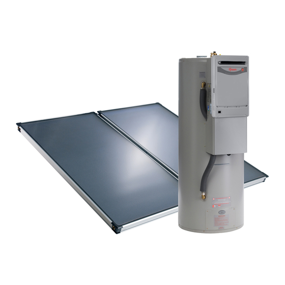
Solar Premier Loline 596270
Gas Boosted Water Heater
WARNING: Plumber – Be Aware
Use copper pipe ONLY. Plastic pipe MUST NOT be used.
It is a requirement of a solar water heater installation that all pipe work be in
copper and not plastic, due to the effects of high water temperatures.
This water heater must be installed and serviced by a qualified person.
Please leave this guide with the householder.
Advertisement
Table of Contents

Related Manuals for Rheem Solar Premier Loline 596270


Summary of Contents for Rheem Solar Premier Loline 596270
- Page 1 Owner’s Guide Installation Instructions Solar Premier Loline 596270 Gas Boosted Water Heater WARNING: Plumber – Be Aware Use copper pipe ONLY. Plastic pipe MUST NOT be used. It is a requirement of a solar water heater installation that all pipe work be in copper and not plastic, due to the effects of high water temperatures.
- Page 2 An electronic copy of these Owner’s Guide and Installation Instructions can be downloaded from rheem.com.au. Rheem Australia Pty Ltd is the supplier of the Rheem range of continuous flow gas water heaters, manufactured in Japan by Paloma Co., Ltd., a world leader in water heater technology and manufacture.
-
Page 3: Table Of Contents
Rheem warranty. We recommend you read pages 7 to 23, and the terms of the Rheem warranty on pages 4 to 6. The other pages are intended for the installer but may be of interest. -
Page 4: Warranty
The decision of whether to repair or replace a faulty component is at Rheem’s sole discretion. If you require a call out and we find that the fault is not covered by the Rheem warranty, you are responsible for our standard call out charge. If you wish to have the relevant component repaired or replaced by Rheem, that service will be at your cost. - Page 5 3. WHAT IS COVERED BY THE RHEEM WARRANTY FOR THE WATER HEATERS DETAILED IN THIS DOCUMENT Rheem will repair or replace a faulty component of your water heater if it fails to operate in accordance with its specifications as follows:...
- Page 6 You are also entitled to have the goods repaired or replaced if the goods fail to be of acceptable quality and the failure does not amount to a major failure. The Rheem warranty (set out above) is in addition to any rights and remedies that you may have under the Australian Consumer Law.
-
Page 7: Safety, Warnings, Installation Notes
The water heater must not be operated unless each of these devices is fitted and is in working order. The Rheem warranty may not cover faults if relief valves or other safety devices are tampered with or if the installation is not in accordance with these instructions. - Page 8 SAFETY, WARNINGS, INSTALLATION NOTES Servicing of a water heater must only be carried out by qualified personnel. Phone Rheem Service or their nearest Accredited Service Agent. Only a person qualified to install or service a water heater can drain the water heater, if this is required.
- Page 9 If water does not flow freely from the drain line when the lever is lifted, then the water heater must be checked. Phone Rheem Service or their nearest Accredited Service Agent to arrange for an inspection. The temperature pressure relief valve should be replaced at intervals not exceeding five (5) years and the expansion control valve should be checked for performance or replaced at intervals not exceeding five (5) years.
-
Page 10: About Your Water Heater
Freeze conditions occur below 6°C. SOLAR OPERATION The Rheem Premier Loline solar water heater has its vitreous enamel lined solar storage tank installed at ground or floor level, remotely from the solar collectors. This water heater is a closed circuit solar hot water system with a heat exchanger in the solar storage tank. - Page 11 The preset outlet booster temperature setting of the gas booster cannot be adjusted by the householder. The setting can only maximum recommended be adjusted by Rheem Service or their nearest Accredited Service supply temperature to Agent. The factory preset outlet temperature setting of the gas bathrooms and ensuites booster is 60°C.
- Page 12 The in-series gas booster frost protection system will be rendered inoperable if electrical power is not available at the gas booster. Damage caused by freezing due to the unavailability of power at the in-series “Terms of the Rheem Warranty” gas booster is not covered by the Rheem warranty (refer to on page 4). ...
- Page 13 The red LED may emit up to six (6) flashes in each series of flashes. Count the number of flashes and phone Rheem Service or their nearest Accredited Service Agent to arrange for an inspection.
- Page 14 ABOUT YOUR WATER HEATER FREEZE PROTECTION The water heater has a freeze protection system. The water heater, including the in-series gas booster, is not suitable for installation in areas where the ambient temperature falls below -20°C (including wind chill factor). “Freeze Protection”...
-
Page 15: Maintenance Requirements
Check the performance of the tempering valve if it has pipe work connected. Measure the water temperature from the nearest hot tap to the water heater used primarily for personal hygiene purposes with a thermometer. If the water temperature exceeds 50°C, phone Rheem Service or “Tempering Valve”... - Page 16 Note: The major service and routine replacement of any components, such as the anode and relief valve(s), are not included in the Rheem warranty. A charge will be made for this work. Only genuine replacement parts should be used on this water heater.
-
Page 17: Water Supplies
If an incorrect colour coded anode is used in the water heater, any resultant faults will not be covered by the Rheem warranty. In addition, the use of an incorrect colour coded anode may shorten the life of the water heater cylinder. - Page 18 Where the saturation index exceeds +0.40, the water is very scaling. An expansion control valve must be fitted on the cold water line after the non-return valve to protect and for the Rheem warranty to apply to the temperature pressure relief valve and water heater cylinder.
- Page 19 The water heater, solar collectors and their components are not suitable for certain water chemistries. Those chemistries are listed below. If the water heater is connected at any time to a water supply with the following water chemistry, the Rheem warranty will not cover any resultant faults on the components listed below: Water Chemistry Component Total Dissolved Solids (TDS) >...
-
Page 20: Save A Service Call
SAVE A SERVICE CALL Check the items below before making a service call. You will be charged for attending to any condition or fault that is not related to manufacture or failure of a part. COLD WATER FROM THE HOT TAP ... - Page 21 Collector area is too small For most installations, the number of solar collectors recommended in Rheem literature has been proven to provide the required solar energy to meet the average family needs. However, in some circumstances, it may be necessary to install an additional solar collector.
- Page 22 Heavy flows of hot water from the temperature pressure relief valve until water heater is cold - then stops until water reheats The water heater must be switched off at the isolating switch or switchboard. Phone Rheem Service or their nearest Accredited Service Agent to arrange for an inspection.
- Page 23 Has your water heating tariff rate been increased by your gas retailer since your previous bill? COLLECTOR GLASS The Rheem warranty DOES NOT cover breakage of solar collector glass. Check your household insurance policy covers collector glass breakage. Warning: No attempt should be made to remove or replace broken collector glass.
-
Page 24: Installation - Solar Storage Tank
The connection, attachment, integration or general association of other equipment or parts which either directly or indirectly affect the operation or performance of this equipment could void the Rheem warranty. All packaging must be removed from the water heater prior to its installation. This includes the removal of the cardboard base of the carton from the underside of the water heater. - Page 25 INSTALLATION – SOLAR STORAGE TANK Victorian Installers Notice to Victorian Installers from the Victorian Building Authority if this solar water heater is installed in a new Class 1 dwelling in the State of Victoria. The system model number is to be recorded on the Certificate of Compliance.
- Page 26 INSTALLATION – SOLAR STORAGE TANK A secondary flue is not required. The water heater must not be installed indoors or in a confined space. The water heater must be located to ensure that the location of the flue terminal complies with the requirements AS/NZS 5601.1.
- Page 27 Damage to the in-series gas booster caused by either the unavailability of power at the gas booster or freezing “Terms of the of the pipe work to or from the gas booster is not covered under the Rheem warranty. Refer to Rheem Warranty”...
- Page 28 INSTALLATION – SOLAR STORAGE TANK HOT WATER DELIVERY This water heater can deliver water at temperatures which can cause scalding. This water heater has both a tempered water outlet connection and a hot water outlet connection. Tempered Water Outlet The tempering valve on this water heater is WaterMark Certified to AS 4032.2 and is factory set to deliver water not exceeding 50°C from the tempered outlet.
- Page 29 A Rheem 874826 model in-series gas booster can be installed as part of a circulated hot water flow and return system in a building. The connecting pipe work supplied with the water heater may need to be modified in order to install a Tee prior to the water inlet of the in-series gas booster.
- Page 30 If an incorrect colour coded anode is used in the water heater, any resultant faults will not be covered by the Rheem warranty. In addition, the use of an incorrect colour coded anode may shorten the life of the water heater cylinder.
- Page 31 INSTALLATION – SOLAR STORAGE TANK DIMENSIONS AND TECHNICAL DATA Model tank 59627000 Capacity 270 litres Mass 141 kg (empty) 411 kg (full) Nominal gas booster 874826 26 L/min Mass 16 kg 427 kg incl booster Capacity Nominal Test Point Hourly Gas Min.
- Page 32 INSTALLATION – SOLAR STORAGE TANK TYPICAL INSTALLATION – OUTDOOR LOCATION...
-
Page 33: Installation - Solar Collectors
INSTALLATION – SOLAR COLLECTORS SOLAR COLLECTOR LOCATION Consideration must be given to the position of the solar collectors in relation to the solar storage tank. There are limitations on both the maximum length of the solar hot and solar cold pipes and the maximum height “Solar Water Heater Storage Tank Location”... - Page 34 This type of frame should be used if the roof pitch is less than 10° or varies by more than 20° below the optimum angle. Contact Rheem or your local Rheem Solar Water Heater Distributor for details.
- Page 35 INSTALLATION – SOLAR COLLECTORS LATITUDE OF SOME AUSTRALIAN CITIES Adelaide 35°S Cairns 17°S Hobart 42°S Port Hedland 20°S Alice Springs 24°S Canberra 35°S Mildura 34°S Rockhampton 24°S Brisbane 27°S Darwin 12°S Melbourne 38°S Sydney 34°S Broken Hill 31°S Geraldton 28°S Perth 32°S Townsville...
- Page 36 INSTALLATION – SOLAR COLLECTORS Maximum Height To Collectors The solar collectors must be the highest point of the system. The maximum height of the solar installation, from the base of the solar storage tank to the top of the solar collectors, is 9 m for this closed circuit system. The pump supplied with the solar storage tank will not circulate closed circuit fluid through heights greater than 9 m and solar gain will not be achieved.
- Page 37 INSTALLATION – SOLAR COLLECTORS WARNING: Plumber – Be Aware The solar hot and solar cold pipes between the solar storage tank and the solar collectors MUST BE of copper. All compression fittings must use brass or copper olives. The full length of the solar hot and solar cold pipes MUST BE insulated.
- Page 38 INSTALLATION – SOLAR COLLECTORS Pressure Testing The solar water heater, including the collector circuit, is to be isolated during the testing and commissioning of the heated water reticulation system in a building, in accordance with Clause 9.3 (a) of AS/NZS 3500.4:2018. The collector circuit includes the solar hot and solar cold pipes and solar collectors.
-
Page 39: Storage Tank And Gas Booster Assembly
STORAGE TANK AND GAS BOOSTER ASSEMBLY GAS BOOSTER BRACKETS – 874826 MODELS INSTALLER PLEASE NOTE: It is necessary to replace the top mounting bracket with the bracket supplied with the solar storage tank and relocate the bottom mounting bracket on an 874826 gas booster water heater when mounting it on the 596270 model solar tank. - Page 40 STORAGE TANK AND GAS BOOSTER ASSEMBLY Relocating the Bottom Bracket To relocate the bottom bracket: Remove the right most screw adjacent to the bottom mounting bracket. Put aside the screw. Remove the screws securing the bottom mounting bracket at the rear of the gas booster, reposition the bracket across to the right (but do not rotate) of the gas booster (as viewed from the rear face) and refit the screws in the locating holes.
- Page 41 Warning: Sealant must not be allowed in the waterways of pipe work or fittings. Excess sealant may be carried into the water heater where it will damage components and block the internal filters. This damage to components or blockage of filters is not covered by the Rheem warranty and a service rectification fee will be charged.
- Page 42 STORAGE TANK AND GAS BOOSTER ASSEMBLY Mounting the Gas Booster To mount the gas booster onto the solar storage tank: Position the top mounting bracket on the gas booster (3) into the recess of the bracket on the solar storage tank.
- Page 43 STORAGE TANK AND GAS BOOSTER ASSEMBLY Installing the Pipe Cover To install the pipe cover under the gas booster to cover the pipe work and fittings: Position the pipe cover (10) under the gas booster (3), aligning the sides of the pipe cover with the sides of the gas booster.
- Page 44 STORAGE TANK AND GAS BOOSTER ASSEMBLY Diagrammatic – mounting 874826 model to solar storage tank and fittings assembly Components for Assembly of Storage Tank and 26 Litre Gas Booster Hot connection assembly Flexible hose (cold inlet connection) 550 mm long Elbow fitting ¾”...
-
Page 45: Connections - Plumbing
Excess sealant may be carried into the water heater where it will damage components and block the internal filters of the gas booster. This damage to components or blockage of filters is not covered by the Rheem warranty and a service rectification fee will be charged. - Page 46 CONNECTIONS – PLUMBING An isolation valve and non-return valve must be installed on the cold water line to the water heater. An “Hot Water Delivery” acceptable arrangement is shown in the diagram on page 45. Refer also to on page 28 “Mains Water Supply”...
- Page 47 CONNECTIONS – PLUMBING Using a spanner engaged on the valve’s spanner flats and applying medium pressure to tighten, turn the relief valve an additional ½ to 1 ½ turns to secure and make the joint water tight, leaving the valve drain pointing downwards.
- Page 48 Disconnect the gas booster after the isolating cock to prevent the risk of serious damage to the gas control. The Rheem warranty does not cover damage of any nature resulting from failure to observe this precaution. Refer to rating label for gas types and pressures.
-
Page 49: Connections - Electrical
CONNECTIONS – ELECTRICAL The power supply to the water heater must not be switched on until the solar storage tank is filled with water. MEGGER READING It is not mandatory to conduct a megger test on a plug in appliance, however if a megger test is conducted on this water heater, then the following should be noted. - Page 50 CONNECTIONS – ELECTRICAL HOT SENSOR LEAD House the hot sensor lead at the water heater in the flexible conduit provided and secure the conduit in the cut out on the tab located behind the upper front cover. Connect the hot sensor cable to the hot sensor cable connector located on the tab behind the upper front cover.
-
Page 51: Commissioning
COMMISSIONING TO FILL AND TURN ON THE WATER HEATER The power supply to the water heater must not be switched on until the solar storage tank is filled with water. To fill the solar storage tank with water and turn on the water heater: ... - Page 52 COMMISSIONING The tempering valve is factory set to provide 50°C limited hot water at the tempered water outlet. If it is “Outlet Temperature Compensation Adjustment” necessary to adjust the outlet temperature, refer to page 65. Explain to the householder or a responsible officer the functions and operation of the solar water heater. Warning: Upon completion of the installation and commissioning of the water heater, leave this guide with the householder or a responsible officer.
- Page 53 COMMISSIONING Warning: Although non-toxic, the following first aid advice and procedures should be followed if the closed circuit fluid concentrate comes into human contact or is spilt: Swallowed - give milk or water and seek medical attention. Eyes - wash with running water. ...
- Page 54 COMMISSIONING Commissioning the Solar Circuit To commission and check the solar circuit: Switch off the electrical supply at the power outlets to the solar storage tank and gas booster. If the pump has been operating, wait five minutes to allow the drain back of the closed circuit fluid in the solar circuit.
- Page 55 COMMISSIONING Disconnect the drain line from the solar circuit relief valve at the top of the solar storage tank. Remove the spring clip from the solar circuit relief valve and remove the valve. Warning: The solar circuit may be under pressure. Take care when removing the solar circuit relief valve, as disconnect a sudden discharge of pressurised hot vapour may be...
- Page 56 COMMISSIONING Check the closed circuit fluid is circulating around the solar circuit. To check circulation: Listen for the trickling sound of the closed circuit fluid returning into the heat exchanger by placing your ear against the side toward the top of the solar storage tank. If the fluid is circulating around the solar circuit, a trickling sound will be heard as the fluid returns back into the heat exchanger.
- Page 57 COMMISSIONING Drain Back Function Switch off the electrical supply at the power outlet to the solar storage tank. The red LED on the solar monitor label will stop flashing. The pump will deactivate. The closed circuit fluid will drain back down to the heat exchanger and the level of the closed circuit fluid in the clear hose will rise.
- Page 58 COMMISSIONING Closed Circuit Fluid Level Measure the distance from the text marking “MINIMUM FLUID LEVEL WITH PUMP OPERATING” to the closed circuit fluid dynamic level marked on the side of the solar storage tank during step The correct closed circuit fluid dynamic level for efficient operation of the system when the pump is operating is between the “MINIMUM FLUID LEVEL WITH PUMP OPERATING”...
- Page 59 COMMISSIONING Determine the correct amount of water to be added to or closed circuit fluid to be drained from the heat exchanger if the dynamic level is either below the text marking “MINIMUM FLUID LEVEL WITH PUMP OPERATING” or more than 150 mm above this mark. Each 100 mm of fluid level height is equivalent to three (3) litres of closed circuit fluid.
- Page 60 COMMISSIONING Add water to top up the level of the closed circuit fluid in the heat exchanger if required. To add water to the closed circuit fluid: If not already removed, disconnect the drain line and remove the spring clip from the solar circuit relief valve at the top of the solar storage tank and remove the valve (refer to step Warning: The solar circuit may be under pressure.
- Page 61 COMMISSIONING Pressure Testing the Solar Circuit Close the heat exchanger drain valve. heat exchanger drain valve Refit the solar circuit relief valve, orientating the valve closed outlet to the rear of the solar storage tank. Secure with the spring clip. Reconnect the drain pipe to the valve. Switch on the electrical supply at the power outlet to the solar storage tank.
- Page 62 COMMISSIONING Remove Closed Circuit Fluid Level Hose Remove the clear hose from the solar storage tank when satisfied the commissioning procedure is complete. To remove the hose: Ensure the heat exchanger drain valve is closed. heat exchanger Remove the hose from the side of the storage tank drain valve closed and place the end into a container to collect the...
- Page 63 COMMISSIONING DIAGNOSTIC FEATURES OF THE SOLAR CONTROLLER The solar storage tank incorporates a solar monitor which is connected to the solar control module by a ribbon cable. The solar monitor is located on the lower front cover and houses both a green and a red LED. The green LED, marked “Solar”, indicates the current operational mode of the solar water heater and the red LED, marked “Attention”, indicates a fault mode.
- Page 64 The frost protection system of the gas booster will be rendered inoperable if electrical power is not available at the gas booster. Damage caused by freezing due to the unavailability of power at the gas booster is not covered by the “Terms of the Rheem Warranty” Rheem warranty (refer to on page 4). ...
- Page 65 COMMISSIONING OUTLET TEMPERATURE COMPENSATION ADJUSTMENT The maximum outlet temperature from the tempered water outlet may be adjusted to compensate for temperature losses in the pipe work between the water heater outlet and sanitary fixtures. This adjustment may only be made by a plumber. Warning: After adjustment of the tempering valve, the water temperature MUST NOT exceed 50°C from the first tap in the hot water pipe work after the water heater used for personal hygiene purposes, such as in a bathroom or ensuite.
-
Page 66: Draining The Water Heater
DRAINING THE WATER HEATER GAS BOOSTER WATER HEATER To drain the gas booster water heater: “To Turn Off The Water Heater” Turn off the water heater (refer to on page 64). Open a hot tap (preferably the shower outlet). ... - Page 67 DRAINING THE WATER HEATER HEAT EXCHANGER Warning: Exercise care, as fluid discharged from the heat exchanger may be of a very high temperature. To drain the heat exchanger: Switch off the electrical supply at the power outlet to the solar storage tank. ...
- Page 68 Revision Date: 2020 October 122594A...
Need help?
Do you have a question about the Solar Premier Loline 596270 and is the answer not in the manual?
Questions and answers