Table of Contents
Advertisement
Twin Wall Installation Instructions
And
Maintenance Guide
Available in black powder coated, as well as stainless.
Please read all instructions before beginning your
installation. Failure to install this system in accordance with
these instructions will invalidate the conditions of
certification and the manufacturer warranty.
1
Advertisement
Table of Contents

Summary of Contents for Firepower Clearline AKW
- Page 1 Twin Wall Installation Instructions Maintenance Guide Available in black powder coated, as well as stainless. Please read all instructions before beginning your installation. Failure to install this system in accordance with these instructions will invalidate the conditions of certification and the manufacturer warranty.
-
Page 2: Table Of Contents
Page 2 FUELS AND APPLIANCES ......Page 3 GENERAL INSTALLATION REGULATIONS ..Pages 3-5 DIAGRAMS FOR TYPICAL FLUE LAYOUTS..Page 6 CLEARLINE AKW COMPONENTS ....Pages 7-21 MAINTENANCE AND CHIMNEY CLEANING..Page 21 OFFSET CHARTS........Page 22 CHIMNEY HEIGHTS........Page 23-24 WARRANTY.......... -
Page 3: Fuels And Appliances
FUELS AND APPLIANCES CLEARLINE AKW conforms to BS EN1856-2. It is an all stainless steel insulated chimney system designed to be used with solid fuel, biomass, oil or gas, and with both condensing and non-condensing boilers. Clearline AKW has been tested to have a working temperature of 600°C. - Page 4 All chimney installations should comply with Document J of Building Regulations. https://www.gov.uk/government/uploads/system/uploads/atta chment_data/file/468872/ADJ_LOCKED.pdf The Clearline AKW Chimney requires a 50mm clearance to combustible material including timber joists stud walls, plasterboard and plywood. On condensing flue systems, where seals are fitted, the clearance to combustible material is reduced to 20mm.
- Page 5 This may require the adaptor tail to be cut down. NOTICE PLATE The Notice plate for Clearline AKW should be marked up in indelible ink and securely fixed in an unobtrusive but obvious position within the building such as: •...
-
Page 6: Diagrams For Typical Flue Layouts
Typical internal flue system Typical external flue system... -
Page 7: Clearline Akw Components
CLEARLINE AKW COMPONENTS *** Denotes flue diameter ie: 150mm = 02-150-001 or 30-150-001(for black) Please be aware that not ALL components are available in Black, such as components that are normally concealed. STARTING COMPONENTS SW-TW ADAPTOR Code:02-***-001 Tapered adaptor for connecting to traditional stoves with a flue collar, or going from single skin to twin wall, same diameter. - Page 8 SW-TW FLAT INCREASING ADAPTOR Code:02-125-009 Eg: For connecting directly from 125mm outlet on European stove (without a standard flue collar) to 150mm twin wall. ADAPTOR TO FLEX Code:02-***-099 Used to convert from Twin wall insulated flue beneath, to flexible liner above. Includes a locking band.
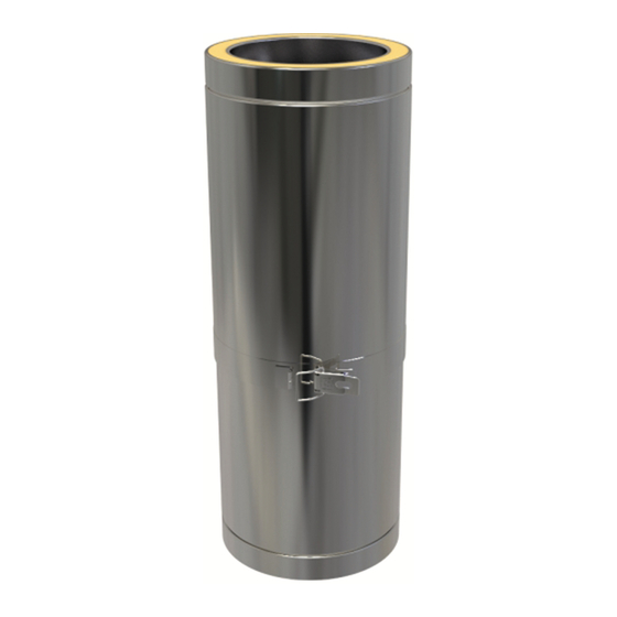
- Page 9 FLUE LENGTHS All flue lengths include a locking band. 1000MM LENGTH Code:02-***-010 Working length 957mm 500MM LENGTH Code:02-***-011 Working length 457mm 250MM LENGTH Code:02-***-012 Working length 207mm 100MM LENGTH Code:02-***-018 Working length 65mm 1000MM CONNECTING STARTER LENGTH Code:02-***-021 Working length 957mm – with integrated adaptor. This length allows the Clearline Single Skin flue to socket up into the section by 325mm, then back down to connect to the stove.
- Page 10 Working length 457mm, including analysis port PELLET GASKET Code:15-***-102 A rubber seal used on condensing installations to stop the condensates from penetrating the flue. The Product Designation for Clearline AKW with seals fitted for condensing appliances is: EN1856-2 T200-P1-W-V2-L50040 0(20)
- Page 11 BENDS AND TEES All bends and Tees are fully welded on the inside and outside and come with a locking band. Please note - Flue pipe bends are measured in degrees from the vertical plane. Roof pitches are also measured in degrees, but from the horizontal plane.
- Page 12 TEE CAP WITH DRAIN Code:02-***-037 For condensing systems or systems with an open terminal. 45 DEGREE BEND Code:02-***-031 30 DEGREE BEND Code:02-***-032 15 DEGREE BEND Code:02-***-033...
- Page 13 SUPPORTING COMPONENTS Clearline AKW Twin Wall can extend 1.5metres above the roof without extra support. JOIST SUPPORT Code:15-***-068 Flue support used on horizontal joists or timbers when passing into a cold roof. It can be used on the floor in a loft to replace second ventilated ceiling support.
- Page 14 130-210MM WALL BAND Code:15-***-053 Provides lateral support, to be used every 1500 -2500mm 210-420MM WALL BAND Code:15-***-055 Provides lateral support, to be used every 1500 -2500mm. CORNER WALL BAND 270-520MM For corner installations to replace a standard wall band giving a balanced look.
- Page 15 STRUCTURAL LOCKING BAND Code:02-***-054 Increases the maximum unsupported height of the flue from 1.5m to 2.5m, one should be used on the joint below the roof support, and on each joint above the roof, except the termination, replacing the standard locking band. Code:15-***-069 FLOOR SUPPORT BAND/GUY WIRE BRACKET The Floor Support Band sits on top of the upper ventilated ceiling support.
- Page 16 Code:02-***-062 Used for truncated systems, changing from a flexible liner inside a masonry chimney to Clearline AKW Twin Wall insulated flue above. Holes already drilled in each corner for fixing the plate down. The flexible liner connection utilises the screw fitting detail.
- Page 17 PENETRATION COMPONENTS SOLID FIRESTOP PLATE Code:02-***-070 Mainly used in gas or oil installations. For solid fuel installations, can only be used to go through a floor in a single storey building into a non-habitable cold loft space. WHITE VENTILATED FIRESTOP PLATE Code:02-***-073 Used when penetrating a ceiling or floor in a domestic installation.
- Page 18 WIDE ROUND FINISHING PLATE 0-30 DEGREE Code:15-***-108 150mm wide. Covers any gap to combustibles, or making good around flue as it passes through ceilings or walls. WIDE ROUND FINISHING PLATE 30-45 DEGREE Code:15-***-109 150mm wide. Covers any gap to combustibles, or making good around flue as it passes through ceilings or walls.
- Page 19 FLASHINGS Traditional lead, nu-lead and aluminium flashings for tiled roofs, and EPDM flashings for flat and profiled roofs – we have a full range of sizes available. Please see website for details. STORM COLLAR Code:15-***-082 Provides a skirt to deflect water. Positioned an inch or so above the flashing. When fitting, a bead of silicone should be used round the top to seal.
- Page 20 ANTI -DOWNDRAUGHT COWL Code:02-***-091 Includes a locking band. Helps to prevent downdraft and rain entry. Used on chimneys subject to strong prevailing winds, or where tall trees or buildings are in close proximity. SPINNING COWL Code:02-***-094 Regular maintenance is required for this type of cowl. CONE TOP COWL Code:02-***-093 GAS COWL...
-
Page 21: Maintenance And Chimney Cleaning
INSULATION COVER PLATE Code:02-***-104 Used to close off a flue system to cover any exposed insulation material. Can be used when using a generic cowl or when no rain cap is required. ACCESSORIES DRAUGHT STABILISER Code:15-***-007 Helps to regulate the draught within the chimney, used with a flue length with a door eg: 90 degree T. -
Page 22: Offset Charts
It is recommended that chimneys serving solid fuel appliances be swept as frequently as necessary, but at least once a year. Chimney flue cleaning and inspection require the use of appropriate equipment – under no circumstances should chemical cleaners or mild steel tools be used to sweep stainless steel chimneys. -
Page 23: Chimney Heights
CHIMNEY HEIGHT Flue outlet heights for standard roofing materials Point where flue passes through weather Clearances to flue outlet surface (Notes 1,2) At or within 600mm of the ridge At least 600mm above the ridge At least 2300mm horizontally from the nearest point on the weather surface and: a) At least 1000mm above the Elsewhere on a roof (whether pitched... - Page 24 These are the recommended heights that you can use as a way of meeting the building regulation requirements. Very simplified these recommendations can be summed up in the following way: The horizontal distance from the top of the flue pipe to the roof should be at least 2300mm, or above the ridge.
-
Page 25: Warranty
Used in combination with an appliance burning only approved fuels in accordance with Clearline AKW and the appliance manufacturer’s instructions. The warranty covers parts only, labour is not included.
Need help?
Do you have a question about the Clearline AKW and is the answer not in the manual?
Questions and answers