Table of Contents
Advertisement
Quick Links
clik
clik
clik
clik
NG
NG
NG
NG
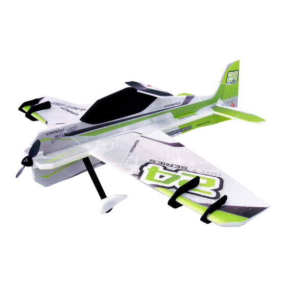
MOTOR: 14 to 19g / 40 to 60w outrunner
ESC: 6 to 12 amp
SERVOS: 2x 4-6g / 1x 8-11g
PROP: 2s/9x4.7 or 3s/8x4.3 prop
BATTERY: 2s 250-360mAh LiPo
Rev: 2014.11.04.v001a
USA Distributor
Twisted Hobbys
www.twistedhobbys.com
RADIO: min. 4 channel
WINGSPAN: 33 inches
LENGTH: 37 inches
AUW: 120 to 130 grams
BARE AIRFRAME: 65 grams
1
Advertisement
Table of Contents

Related Manuals for RC Factory Twisted Hobbys clik NG


Summary of Contents for RC Factory Twisted Hobbys clik NG
- Page 1 clik clik clik clik MOTOR: 14 to 19g / 40 to 60w outrunner RADIO: min. 4 channel USA Distributor ESC: 6 to 12 amp WINGSPAN: 33 inches Twisted Hobbys SERVOS: 2x 4-6g / 1x 8-11g LENGTH: 37 inches PROP: 2s/9x4.7 or 3s/8x4.3 prop www.twistedhobbys.com AUW: 120 to 130 grams BATTERY: 2s 250-360mAh LiPo...
-
Page 2: Table Of Contents
TABLE OF CONTENTS TABLE OF CONTENTS TABLE OF CONTENTS TABLE OF CONTENTS Page WARNING INFORMATION ............................... 3 SHIPPING DAMAGE..................................3 OUR MISSION....................................3 SAFETY NOTES.................................... 4 IMPORTANT: PRIOR TO ANY ASSEMBLY........................4 KIT CONTENTS.................................... 5 OPTIONAL PARTS..................................6 TOOLS & ADHESIVES NEEDED .............................. 7 THE BUILD.................................... -
Page 3: Warning Information
TWISTED HOBBYS Website: www.twistedhobbys.com – email: sales@twistedhobbys.com Thank you for your purchasing a Twisted Hobbys’ model. Please read through the entire manual before beginning to build this model. If you have any questions please contact us at the above indicated email address. WARNING INFORMATION WARNING INFORMATION WARNING INFORMATION... -
Page 4: Safety Notes
SAFETY NOTES SAFETY NOTES SAFETY NOTES SAFETY NOTES Before assembling and flying this model, read carefully any instructions and warnings of other manufacturers for all the products you installed or used on your model, especially radio equipment and power source. Check thoroughly before every flight that the airplanes’... -
Page 5: Kit Contents
kit contents kit contents kit contents kit contents PARTS LIST Kit Contents Carbon Rounds and Strips IMPORTANT NOTE - READ BEFORE STARTING YOUR BUILD 0.8mm x 500mm (tail pushrods) 3mm x 0.5mm x 680mm (wing spar) Vert Fuselage 3mm x 0.5mm x 500mm (wing stiffener) Horz Fuselage 1mm x 250 (wing strut) When your kit arrives check that everything has... -
Page 6: Optional Parts
OPTIONAL PARTS OPTIONAL PARTS OPTIONAL PARTS OPTIONAL PARTS Perfect choice for building and repairing your Twisted Hobbys EPP planes! This is the only adhesive you will ever need. 14g 1620 kV Crack Series Motor Welder virtually bonds anything Blenderm tape is one of the 6A TH-CS ESC to anything! Clear, heavy-duty, best know tapes used for... -
Page 7: Tools & Adhesives Needed
Tools Tools Tools Tools & & & & Adhesives Needed Adhesives Needed Adhesives Needed Adhesives Needed • Lighter • Small drill bits • Tape Measure and Ruler • Black Sewing Thread • Welders Glue • Hobby Knife w/new Blade • Needle Nose Pliers •... -
Page 8: The Build
THE BUILD THE BUILD THE BUILD THE BUILD CONSTRUCTION METHODS: Building surface should be at least 2ft x 4ft and flat. Weights or some small heavy objects will be handy for holding things in place during the time glue is setting. Welders glue is used for FOAM TO FOAM joints. - Page 9 Locate the thin rectange that is 3mm x Test fit the strip into the precut curved Make sure that the strip is flush to the 0.2mm x 330mm (approx 13 inches) slot, it should fill the slot from end to surface of the elevator over the entire length Before applying the CA, make sure...
- Page 10 Use Welders and the tack up method Once the Welders has tacked up, bring Locate the 3mm x 0.5mm x 500mm (thin coat on each mating surface and the two parts together making sure to strip (approx 17in long) let dry for approx 5 minutes) to attach keep the surfaces flush the elevator Constrain everything flat and lay the...
- Page 11 Repeat the process with the other wing Prepare the wings to be attached with Once the glue has tacked up, bring the the tack up method pieces together Wings attached and ready to attach the Dry fit and hold everything in place. Close up of how the weights and stick 3mm x 0.5mm x 680mm strip to the Weights and stick pins can be used to...
- Page 12 Apply CA to the edge of the strip so that Wipe away any extra Apply Kicker behind it wicks in the strip Leading edge strip installed, weights Use Welders and the tack up method to Assemble the two parts once the glue and pins taked away attach the leading edge extenders has tacked.
- Page 13 Locate the 3mm x 0.5mm x 500mm Lay the spar into the slot just forward Apply thin CA and hit with Kicker (approx 20in long) spar of the aileron hinge bevel Locate the two round 0.8mm dia x Cut them to length and fit into the Apply thin CA and Kicker 500mm pieces precut slot.
- Page 14 Attach the nose section using the Once the glue has tacked up bring the If you have not already done it, make a Welders tack up method parts together, make sure the slots in new program on your radio and check each section are in line functionally of all the electronics Install the elecator servo as shown...
- Page 15 Remove the fuselage section and lay Before the glue has a chance to set, Locate the small plastics parts tree down a medium bead of Welders where tweak the lower fuselage so that it is the two parts will meet. Install while the square.
- Page 16 Once the glue has tacked up install as Remove the aileron control horns from Dry fit into the slot, right next to the shown, again, nose of the airframe is to the small plastic tree. The aileron horns end of the carbon strip. Note this is the the left, and use the notches for are the larger ones and are the same area that was left free of glue earlier in...
- Page 17 Dry fit the brace into the front hole in Rod shown here installed into the slot Do the same for the rearward rod... the little half moon doubler and the near the leading edge small slot in the foam near the leading edge ...
- Page 18 Sight down the length of the fuselage to Cut three or four little slits in the area Apply a drop of thin CA to the four ensure that as well as square, that is is shown, just above were the rods are points on the Wing also straight and true inside the foam, these slits will allow...
- Page 19 With 5 of the 0.8 x 500mm rounds make the following length pieces. #1 - 2 pieces 142mm long #2 - 2 piceces135mm long #3 - 2 pieces 134mm long #4 - 2 pieces 128mm long #5 - 2 pieces 159mm long #6 - 1 piece 149mm long All the rods cut to length, note that Starting from just behind the wing...
- Page 20 With medium CA and Kicker, attach the With the tack up method, attach the Add a drop of medium CA into the flat axle holder to the end of each small "T" shaped doublers as shown. round hole landing gear strut (the round carbon Make sure to build a left and right pieces that are 1.5mm x 220mm) Insert the axle and hit with Kicker...
- Page 21 Once again make sure everything is Glue the front brace at both ends and Round up all the pieces to build the nice a square the struts at the horizontal fuselage aileron differential horn and the control ONLY. Leave the area where the struts rod ends pass thru the vertical fuselage piece free of glue for now...
- Page 22 Now you can remove the fuselage from Fully seat the servo into it's position. Fit the rudder servo into it's position. the work bench, test fit the aileron No glue at this time. Depending on the Power Set servos fit perfectly, other servo.
- Page 23 Test fit the upper fuselage section to Look everything over closely and make Remove the upper fueslage and lay the airframe, depending on the servos sure the fit up is nice and flush at all down a medium bead of Welders to used, there may be some trimming the mating surfaces entire length of the mating area...
- Page 24 Locate the two thin rectangles from the Round off the ends as shown Locate the two slots on the right side of hardware bag that are approx 6in long the fuselage... one slot is by the landing gear struts the other is right behind the canopy area You will need to open up the slot a little Slide the spar in as shown...
- Page 25 Repeat the dry fit process for the front Vertical strip should pass BETWEEN Make sure everything is nice and spar. Note that the front spar should the two landing gear struts square past between the landing gear struts as shown in the next step Check the front area as well Once satisfied with the squareness, ...
- Page 26 OPTION #1 OPTION #2 ... stick one of the aileron push rods Wrap the intersection of the spar that With the tip of the Welders tube, thru the axle holes and use as a guide was just installed and the landing gear squeeze some glue into and all around to measure against to ensure that the struts with thread, level the gear then...
- Page 27 In prep for installing the rudder horn, Locate the thin spar (approx 3in long Dry fit the two pieces bend the rudder to extreme position from the hardware pack) and the horn and mark with a fine tip Sharpe at the as shown intersection as shown Locate the hole of the horn directly...
- Page 28 Repeat the Sharpe line process with the Apply thin CA and Kicker Test fit the Rudder as shown. Standing elevator and dry fit the elevator horn the airframe up on it's nose will make aligning everything a little easier once the Welders is applied Tack up method should be used to join Once the Welders is tacked up, bring...
- Page 29 Make sure it all went together nice and ... check it from all angles Locate the push rods that were built in square... an earlier step... they should have had time to cure for 24hrs by now, if wanting you can install the shrink tubing, but this is not needed..
- Page 30 Slide 6 of each on to the two longer Position the snap link end of the push ... and snap into the hole push rods as pictured above rod as shown..Dry fit the ends of the guides into the Position them so that they are all Once satisfied, put a drop of thin CA at pre-cut holes.
- Page 31 Repeat the process with the rudder Snap link installed. Do the guides like Locate the four trailing edge air-brake pushrod, for best alignment snap in you did with the elevator push rod pieces as shown from the top Lay down a thin bead of Welders along Install WET, using the tabs to help with ...
- Page 32 Check to make sure that it is square Locate the 4 Side Force Generators and NOTE - The larger one will install in the and straight cut them free of each other outer most position. They are "keyed" so they will only go together one way Use Welders wet method and mount as Make sure they are fully seated and Locate the parts for the T-Canalizer...
- Page 33 Apply a bead of Welders to the top of Split the little gussets pieces down the Install the T-Canalizer while the glue is the canopy as shown where it will middle still wet mount Motor mount is next... Tack Up method Once the glue has tacked up, attach the Install the wheels and pants.
- Page 34 Use some small blocks or other similar Adjust everything so that it is all square Once satisfied, apply some medium item to hold the wheel/pant assy in and perpendicular CA... position, also a scrap of foam is used to locate the trailing edge of the wheel pant slightly above the work surface ..
- Page 35 ... and that they are in line with the Flip the airframe upside down and add Leave the plane on it's back for the next direction of flight a little more medium CA and Kicker to step. Some large blocks or soft drink the axles areas cans can be used to hold the plane in this position...
- Page 36 Slide the control rods thru the Install the snap links into the aileron ... make sure the servo is centered, and adjustable blocks as shown. Note that horns... that the aileron control surface with the the rods should install under the struts fuselage then snug up the set screw.
- Page 37 Prepare the tail servo arms as shown. Locate electronc approx as shown. Try Close up of installed electronics Note - with the Twisted Hobbys' CS40 and locate items as far forward as servos, the horns ARE long enough for possible the control throws needed for this plane Look every thing over.
- Page 38 Adjust elevator control throws to Adjust rudder control throws to Program in approx 60% expo on the +/- 45 degrees +/- 45 degrees ailerons and 40% expo on the rudder and elevator Control throws and expos can be Locate the battery so that the CG is Battery shown in position.
- Page 39 This completes the build. The design intent of this plane is for indoor F3P and Precision Pattern style flying. Although more durable that it's Depron counter parts it is not as durable as the standard 32" Twisted Hobbys' foam planes, so some care should be taken in storage, transport and flying activities.
-
Page 40: Center Of Gravity
Center of Center of Center of Center of Control Throws Control Throws Control Throws Control Throws Gravity Gravity Gravity Gravity Extreme & F3P CG - 245mm from the nose of aircraft Ailerons - approx +/- 45 deg Rudder - approx +/- 45 deg Elevator - approx +/- 45 deg Expo to suit Beginner &... -
Page 41: Pre-Flight & Testing
PRE- - - - FLIGHT & testing FLIGHT & testing FLIGHT & testing FLIGHT & testing Preflight Checks Flight Testing Motor The first flights should be done with the CG at the Should run smoothly at all stick positions, and recommended position, and reduced control rates until transition smoothly from low to high RPM. -
Page 42: Notes & S/U Sheet
NOTES NOTES & s/u Sheet NOTES NOTES & s/u Sheet & s/u Sheet & s/u Sheet Rev: 2014.11.04.v001a... -
Page 43: Tips And Tricks
TIPS AND TRICKS TIPS AND TRICKS TIPS AND TRICKS TIPS AND TRICKS A good building surface is “drop ceiling” panel from a local hardware store on a nice flat board • Use parchment paper between the areas being glued and your work surface •...
Need help?
Do you have a question about the Twisted Hobbys clik NG and is the answer not in the manual?
Questions and answers