Advertisement
-
For ailerons, use 8 to 11g type servo, for the tailfeathers use 6 to 7g servos. The quality of servos will
greatly influence your flying experience. Set all servos to their neutrals.
-
To achieve free and light movement of all surfaces, deflect them to the maximum (180°) and weigh
them down in this position for min. 3 hours or better overnight. This way the hinge material will stretch
and relax for easier deflections later
-
Consider your flying skills – if you require maximum throws, use the extension servo horns for elevator
and rudder servos and use the outer holes in the aileron servo horn. Longer lever on the horns means
that you should use servos with high available torque.
-
The whole model, unless otherwise stated, can be glued with cyanoacrylate (CA) or contact (Welders,
UHU-Por) glue. Neither has to be styro safe.
The point numbers below respond to the particular Diagrams:
1.
Attach (which means "glue together using CA or contact glue") the horizontal stabilizer to the
backbone. Install the elevator servo and fix it in place (you may use hot glue or tiny drops of medium
thick CA or your favorite method – never use thin CA as it may seep into the servo and ruin the
mechanical parts inside).
2.
Cut the fuselage into 2 parts (Diag. 2). Attach the lower part of the fuselage to the backbone (make sure
the backbone is upside down – elevator hinge V-cut facing up). Glue the 45° torsion strips in place.
3.
Install the rudder servo and fix it in place. Attach the upper fuselage part (still without the canopy).
Using sharp knife, cut through the vertical slit and install the spruce vertical reinforcement spar (2 x 9 x
150 mm). Install also the front wooden reinforcement (2x9x90).
4.
Install the wooden spars into the wings. Install the wooden reinforcements (1.5 x 5 x 150) into the wing
struts.
5.
For the aileron pushrods use carbon rods 1.5 x 110mm. Attach the Z bends to the rods using the
included shrink tubing (5 a,b,c) and drop of thin CA. Attach the extension horn to your aileron servo
horn. You may drill 1 mm holes through both original and extension horns and insert small pieces of 1
mm rods (cut from the tailfeather pushrods). CA glue the small pieces in place, cut them down to the
necessary size.
6.
Install the aileron servo into the wing, respecting the cut-out shape in the fuselage. Re-drill the aileron
horns to 0.8 mm diameter and install the adjustable links (secure with the included quick-lock washers).
Cut the aileron locations all the way through the ailerons (the cuts are partially done in the right length –
all you have to do is cut them all the way through the foam). Install the horns into the ailerons (using
CA). Insert the aileron pushrod z-bends into the extended servo horn and on the other side into the
adjustable links on the aileron horns. Insert the aileron servo horn on the servo and secure with a screw.
Tighten the adjustable links in the correct (neutral ailerons) position. Now you may try your aileron
function.
7.
Lay the lower wing on your workbench, leading edge on the edge of the bench. Carefully slide the
fuselage onto the wing, the servo must fit in the respective cut-out. Attach the wing to the fuselage (this
time we suggest CA). Cut through the wing along the fuselage, next to the spar, to make a slot for the
plywood reinforcement tab. Install the tabs, make sure that your fuselage is square to the wing and glue
the tab in using thin CA. Glue the struts into the wing (they are symetrical, only make sure that they are
in the position skewed to the front of the model – as per Diag. 7).
8.
Lay the upper wing, upside down, on your workbench. Insert the rest of the model, inverted, into the
correct slots. The model is now resting on the workbench via the stub of the vertical stabilizer. Insert
the upper plywood reinforcement tabs and glue them in, and everyting together, using CA (first make
sure that everything is square and true). Prepare your interaileron pushrods (carbon 1.5 x 165 with z-
bends on each end, just like you did in step 5). The inter-axial distance of the opposing z-bends is 162
mm. Insert the z-bends into the particular plywood horns. After making sure that all ailerons are in
neutral position, glue the horns into the ailerons (using CA).
9.
Attach the canopy and the rudder part to the fuselage. Locate the elevator and rudder pushrods (diam 1
mm x 500mm). Attach the z-bends like you did in the aileron case (shrink tubing and all). Glue all the
pushrod guides/supports into the fuselage. The elevator guides are glued either into the backbone
(elevator) or to the upper fuselage (rudder). There are small slots pre-cut for the guides. The pushrods
should be located approx 5 mm from the fuselage.
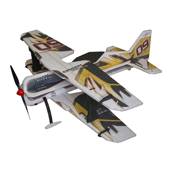
Crack Pitts
Building Instructions
Advertisement
Table of Contents

Related Manuals for RC Factory Crack Pitts


Summary of Contents for RC Factory Crack Pitts
- Page 1 Crack Pitts Building Instructions For ailerons, use 8 to 11g type servo, for the tailfeathers use 6 to 7g servos. The quality of servos will greatly influence your flying experience. Set all servos to their neutrals. To achieve free and light movement of all surfaces, deflect them to the maximum (180°) and weigh them down in this position for min.
- Page 2 1x servo 9 - 10g (ailerons) motor cca 60+ W, 20 - 30g (typically 2204 to 2206 type motor) brushless ESC 10-12A battery 2S 450 mAh We wish you many happy flying hours with the Crack Pitts. Your RC Factory team.
- Page 3 Horní køídlo 2x9x150 2x9x90 1,5x5x150 2x7x600 Spodní køídlo 162mm pohled zepøedu 185 mm 2s 450...
Need help?
Do you have a question about the Crack Pitts and is the answer not in the manual?
Questions and answers