
Related Manuals for RC Factory Complete set Yak 55


Summary of Contents for RC Factory Complete set Yak 55
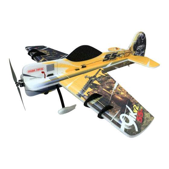
- Page 1 Complete set Yak – Instructions In this manual we are going to build a complete Yak 55 airplane. Part of the set is the key equipment that the pilot needs to fly the EPP airplane.
- Page 2 In the set you can find: You will need: • • Yak 55 airplane 4x AA batteries • • RC radio with receiver Hobby Knife • • Motor Small Phillips and Flat Screwdriver • • Serva Small pliers or tweezers •...
- Page 3 Fold the parts and load them evenly. You can use books, for example. Leave the parts for about 1-2 hours. In the meantime, prepare a space to build the plane. You will need a free table. Since the plane is primarily glued, it is good to cover the table with a piece of plastic, which will protect the table and prevent the airplane from sticking to the table.
- Page 4 Connect the pairing cable to the pins labeled B/VCC on the edge of the receiver. Connect the servo wire from ESC to any position to power the receiver. The orientation of the connector is important. The signal wire (yellow) must face the center of the receiver. Finally, connect the battery. The radio should respond to the receiver and the pairing is complete.
- Page 5 After 1-2 hours, when the parts were loaded, it should be possible to move the ailerons freely without resistance. Prepare the center part of the plane and take out the cuttings.
- Page 6 Let's start with gluing the wing. The wings have differently sized semicircular protrusions. Therefore, it should not happen that you glue the wings in reverse. Apply the activator to the middle part of the plane and glue on the wing then press them firmly together. Be careful not to glue the ailerons. We apply the same procedure to the second wing.
- Page 7 After gluing the wings, take a knife and cut through the groove that runs through both wings and the center. Then glue a wooden reinforcement into the groove. The reinforcement fits into the wing precisely and should not stick out on either the top or bottom side. Apply glue to the reinforcement from both sides, insert it into the groove, spray it with an activator and press the EPP around it firmly.
- Page 8 Next, install the elevator. Spray the elevator with an activator, apply glue to the central part and press tightly. There are protrusions on the elevator and the central part, thanks to which it should not be possible to glue the elevator in reverse.
- Page 9 Take the D10M servo and insert it from below into the prepared cutout in the central part. Secure the servo with glue. Drop the glue in the corners of the servo and spray it with an activator. After gluing the servo, glue the lower part of the airplane to the center part. Be careful not to glue the moving part of the servo.
- Page 11 Now glue the black struts. Spray the bottom of the airplane with an activator and apply glue to the struts. On one edge (which will be in front) leave about 8cm of struts without the glue. The front part of the glue-free strut begins at the line that is drawn in front of the airplane in front of the wooden reinforcement.
- Page 13 Turn the plane over and insert the Volta DM14 servo, which will control the ailerons. Stretch the cable to the underside of the airplane. Then secure the servo from the sides with glue and spray it with an activator.
- Page 14 Put together the lever for the servo to control the ailerons. The package includes more 3D printed parts for use with other types of servos. The wider part of the lever goes to the place marked by the groove. Take a lever from the D14M servo and insert it into the prepared 3D print.
- Page 15 Now put blimps (that metal thing with a pin) into the 3D printing according to the pictures. Secure the blimp sufficiently with snap ring so that it does wiggle, but it can be rotated freely. The snap ring goes to the pin stiffly, so you need to use a little force.
- Page 16 Put the lever on the center servo according to the picture. Make sure that the servo has not moved and is in the center position. The lever should be as straight as possible (within the capabilities of the teeth on the servo). Finally, lock the lever with a screw.
- Page 17 Prepare the levers for the ailerons. Split the set of levers with a knife and glue the lever into the prepared hole in the aileron on the bottom side. The entire bottom of the lever should be hidden in the wing and not stick out. We repeat for the second aileron.
- Page 18 Prepare the rods. Take 2 shorter rods, heat shrink and plastic forks (ends). Separate 2 plastic forks. Roughen the 1cm of the sticks with sandpaper and apply glue. Then glue sticks to forks. There is a groove on the fork into which the rod will fit. When the rod is in place, spray it with an activator and put on piece of heat shrink.
- Page 19 First, stretch the rod through the servo lever and put a screw in the blimp. Do not tighten the screw yet. Click the fork into the lever on the ailerons from the outer side. Make sure that the aileron is straight and tighten the screw in the blimp.
- Page 20 Repeat the same procedure on the other wing. Prepare the guides. Use only half of the guide set now.
- Page 21 Glue the guides from above to the center part of the plane into the prepared holes. Make sure that the guides are equally oriented so that the rod can go through the holes. Glue a lever into the elevator from the upper side into the prepared cutout. The whole bottom part of the lever needs to be in the EPP.
- Page 22 Prepare the levers for the elevator and rudder servos. Put the blimp in the outer position on the servo lever and secure with the snap ring. Put a screw in the blimp do not tighten it. Put the first lever to the servo in the center of the airplane. Put the lever so that it is perpendicular to the wings of the airplane (it is pointing up).
- Page 23 Secure the lever with a screw. Press on the soft EPP with a screwdriver and bend it to the side so you can screw the screw. Next, prepare the long rods. The procedure is the same as for the short ones. Take two thinner long rods and two forks.
- Page 24 Stretch the elevator rod through the guides to the servo lever through the blimp. Then click the fork into the elevator lever from the outer side.
- Page 25 Make sure that the elevator is leveled and tighten the blimp screw on the servo lever to secure the position of the rod. Leave a piece of the rod behind the blimp for possible corrections and shorten the excess using splitters.
- Page 26 Now install the servo for the rudder. Take the second Volta D10M servo and push the cable through the center part of the airplane to the bottom part. Pull the cable from behind the black strut. Help yourself with tweezers.
- Page 27 When the servo is in place, secure it in corners using glue and spray it with an activator. Then put the second servo lever on the servo and secure it with a screw. The lever is directed away from the elevator rod and is perpendicular to the rod.
- Page 28 Glue the top part to the rest of the plane. Make sure that the upper part is perpendicular to the center of the airplane along the entire length.
- Page 29 Next, attach a rudder. The rudder holds on to airplane by a relatively small piece. Be careful not to glue the moving part of the rudder to the airplane. Put the glue on the part of the rudder in front of the hinge. Apply activator on the plane and press together.
- Page 30 Glue a lever into the rudder from the left side into the prepared cutout. The whole bottom part of the lever needs to be into the EPP. On the left side of the upper part, glue the guides into the prepared cutouts. Make sure that the guide holes are oriented in the same way so that you can stretch the rod through the holes.
- Page 31 Starting from the rudder, stretch the entire rod through the guides and blimp on the servo lever. Click the end fork into the lever on the rudder. Align the rudder to the straight position. Make sure that the servo lever is perpendicular to the top of the airplane and lock the rod with a screw.
- Page 32 Take out the side force generators of the cut-out and cut each one according to the picture.
- Page 33 Glue them to the wings. Put the larger closer to the center of the airplane, the smaller one is on the edge of the wing. Glue the motor mount to the front of the airplane and prepare a motor with an ESC. Screw metric screws into the motor, on which the propeller will be mounted.
- Page 34 Rotate the motor so that the ESC is directed to the cables from the servos. Screw the motor with the ESC to the motor mount using the sharp screws. Glue the ESC to the airplane with a drop of glue.
- Page 35 Finally, install the RC receiver. Place the RC receiver on the center of the airplane between the wooden reinforcement and the printed line. Mark the height of the receiver with a marker and cut a hole for the receiver in the EPP with a knife.
- Page 36 Push the receiver through the hole so that the pins for connecting the servos are on the same side as the cables from the servos. Secure the receiver with a glue, if you made a hole for the receiver a little larger and it moves. Since the Flysky receiver is a little larger, shorten the black struts.
- Page 37 Connect the servos and the ESC and test if everything moves as it should. Starting the first channel, connect the connectors in order: ailerons, elevator, throttle (ESC), rudder. After connecting the connectors, turn on the radio, pull the throttle down and connect the battery to the airplane. If the part of the planes is moving in an opposite direction, it is necessary to reverse the channel in the radio settings.
- Page 38 When the right gimbal is deflected to the right (leave the throttle at the bottom), the right aileron must be raised and the left one lowered.
- Page 39 When the left gimbal is deflected to the right, the rudder turns to the right.
- Page 40 When the left gimbal is deflected downwards, the elevator rises upwards.
- Page 41 Finally, calibrate the throttle. Disconnect the battery from the airplane and put the throttle gimbal all the way up. Plug the battery to the airplane and wait for the ESC to beep. Then pull the throttle down. The ESC plays again and the throttle range is calibrated.
- Page 42 Attach the antennas from the receiver. The antennas should be perpendicular to each other for the best reception. Lead one antenna along the black strut and the other on the wing. Make a notch in the wing with a knife and hide the antenna into it. Thus, the antenna will not protrude from the wing to the outside. Secure the antennas on several places with a drop of glue.
- Page 43 Put the propeller on the plane. Catch the rubber band under one screw, put on the propeller and pull the rubber band over and grab the second screw. If it does not work by hand, you can help yourself with a screwdriver.
- Page 44 Place the battery. Put it on the side with Velcro or cut a hole for the battery in the top of the plane. Place the battery in such a place that the center of gravity is in the marked place (18 cm from the front). If you are going to use the landing gear, install the landing gear first and then tune the position of the battery.
- Page 45 Landing gear construction In this section, you will attach a landing gear to an airplane. For the construction of the landing gear you will need glue, sandpaper and a 2mm drill with a drill. A piece of wood for the drilling will also come in handy. Take the carbon landing gear, laminate wheel holder and wheels.
- Page 46 Roughen the laminate parts from one side with sandpaper. On a roughened surface, glue will hold better. Stretch the carbon landing gear through the prepared hole in the bottom part of the airplane . Align it so that the airplane standing on the landing gear is straight. Glue the leveled landing gear with glue. On the glued landing gear, slide the laminate droplets with the roughened side to the airplane.
- Page 47 Mount the wheels on the landing gear. Take a screw, stretch it through the landing gear and laminate holder and secure it with the nut. The roughened part of the laminate holder is on the outer side. Glue the laminate holder to the landing gear with glue.
- Page 48 Asseble the shoes. The shoes will be symmetrically right and left. Each shoe consists of 3rd parts. The part that has a protrusion at the back comes to the middle. Glue the parts togeather.
- Page 49 Glue the shoes to the laminate holder on the roughened outer part. The landing gear is done.
-
Page 50: Radio Settings
Radio settings The plane is built and now it remains to set up the radio. Get to the settings by long holding down the OK button. To go back, use the Cancel button. Scroll the menu using the Up and Down buttons. Save the selected settings by holding down the Cancel button. - Page 51 Here you can set the size of the deflections for each channel. When the arrow is in the first place in Ch1, use the Up and Down buttons to switch between channels. Press the OK button to move the arrow to the next line. When the arrow is in place near Rate, use the Up and Down buttons to change the maximum channel deflections.
- Page 52 Press Cancel and get back to the main menu. This time select System setup and confirm with the OK button. Scroll down to RX Setup and confirm OK. Select Failsafe and confirm OK.
- Page 53 Failsafe sets the behavior of the receiver in the event of signal loss. It is always necessary to turn off the motor when signal is lost. Otherwise, the plane might fly away. A signal loss does not normally occur, but it is good to be prepared for this situation.
Need help?
Do you have a question about the Complete set Yak 55 and is the answer not in the manual?
Questions and answers