Table of Contents
Advertisement
Advertisement
Table of Contents

Related Manuals for Amylior E-BX


Summary of Contents for Amylior E-BX
- Page 1 E-BX IG-P17008-Instruction Guide E-BX R01...
-
Page 2: Table Of Contents
Error code reading on the joystick’s screen ....................13 Error code reading by counting the number of times the indicator light underneath the e-bx flashes ..14 Error code reading using the program journal of the “R-Net Programmer” application ......15 Error codes table ............................ - Page 3 4.1.5.1.1 Checking battery voltage ......................28 4.1.5.1.2 Verifying power cables ......................... 29 4.1.5.1.3 Verifying R-Net bus cables, actuator cables and intermittent problems ........33 Replacing pushbuttons in keypad (SWKEYPAD): ....................35 Pushbutton replacement ..........................35...
-
Page 4: Programming The Wheelchair
2.1 E-bx settings under the menu “Seating Amylior ISM” Actuator number and its functionality To access all actuators controlled by e-bx, use the following path: “Seating Amylior ISM Actuator Setup”. In this submenu, the legend for each actuator number is as follows:... -
Page 5: Settings Under The "General" Submenu
Settings under the “General” submenu The settings included the “General” submenu are all the adjustments available for setting minimum and maximum limits on each actuator. The following table shows all the possible settings. 2.1.2.1 Settings under the “General” submenu Defaut Settings Applicable actuator Description... -
Page 6: Settings Under The "Actuator Setup" Submenu
Defaut Settings Applicable actuator Description Range settings Minimum setting of right stander actuator (Standing module fully Actuator #6 (Right Min limit #6 (% or °) deployed) minimum angle between the seat plate and the base -70° to 0° stander) Notes 6 et 7 Actuator #6 (Right Maximum setting of right stander actuator (Standing module Max limit #6 (% or °) -
Page 7: Settings Under The "Actuator Setup" Submenu
“Actuator Setup” submenu displays all stander actuator settings for proper position angles to allow a “comfortable” operation i.e. Soft start/stop. To adjust the stander actuator for a soft stop, use “Set point 1”. This position is the first stop when the stander is deployed. This submenu also contains all the settings for actuator movement speeds, acceleration/deceleration, starts and stops. - Page 8 For chairs without the power standing option, the following table shows basic functions assigned to each axis. 2.1.4.1 Table 1: Axis assignment of actuators for chairs without stander Axis number Function/Actuator Tilt Recline Seat elevate Left legrest Right legrest Left & right legrests Recline and Left &...
-
Page 9: Axis Setup" Settings
“Axis Setup” settings These settings are for adjusting certain movements on the different power options. The following table shows all the possible settings. 2.1.5.1 Settings under the “Axis Setup” submenu Settings Applicable actuator: Description Range Default setting Parameter E Not used. Settings for future development. Parameter F Percentage value of speed acceleration Acceleration... -
Page 10: Approximate Length Of Time For Actuator Deployment
Note 2 : Even though the Control setting for the standing function’s axis is adjustable, it is recommended not to change the setting to “proportional”. This can affect the standing function’s performance and create errors while in motion. Before modifying this setting, contact Amylior for approval. •... -
Page 11: Overview Of Both Special Boot-Up Modes
3.2 Activating special boot-up modes When the button underneath the e-bx is held during system start-up, the green LED flashes with a delay of two seconds. The number of flashes corresponds to the mode required. Release the button when the number of flashes equals the mode required. -
Page 12: Second Special Boot-Up Mode
Applicable flashes at start-up on Mode 2 indications Features disabled actuators the e-bx • Allows a minimum and maximum position reset of • Red and green actuators. LEDs on the • All position limits • Works only with pushbutton keypad (SWKEYPAD). -
Page 13: Troubleshooting Guide
Error codes are prompted either on the joystick’s screen, with the number of times the light underneath the e-bx flashes or in the program journal of the “R- Net Programmer” application. This is useful for knowing what direction to take when solving the problem. -
Page 14: Error Code Reading By Counting The Number Of Times The Indicator Light Underneath The E-Bx Flashes
Error code reading by counting the number of times the indicator light underneath the e-bx flashes If there is an error, the green indicator light underneath the e-bx can indicate certain error codes. The error is shown with a two-second pause separating the very first flash and the second flash. During this pause, the light is off. When the light starts flashing, count the number of times it flashes before the light turns off again for another two-second pause. -
Page 15: Error Code Reading Using The Program Journal Of The "R-Net Programmer" Application
Plug the R-Net dongle into the chair by removing one of the R-Net cables connected to the chair, for example, one of the 2 cables connected to the e-bx and turn on the chair using the joystick. Open the PGDT « R-Net Programmer » application and click on Read, the icon with the black arrow point... - Page 16 Click on the Tools tab. Click on Systems Logs menu The following window will appear on the left. Click on the Log tab and select Read menu.
- Page 17 From Module Log Info directory, select e-bx. The list of error codes will appear starting with 4400. The e-bx actual error codes are not shown on the Dealer version of the application. The file containing the error codes must be sent to Amylior to be examined and analyzed. To save the journal of error codes, click on the File tab and select Save to file.
-
Page 18: Error Codes Table
9600 9601 9602 1. Make sure that all connections to the e-bx are secure and that none Problem inside the are damaged. After inspection, turn off the R-Net system and turn it 9603 e-bx controller back on. - Page 19 5. If both R-Net cable buses are properly connected and in good is defective. condition, replace the e-bx controller. 6. Once the e-bx has been replaced and the problem is solved, make sure that power positioning modules do not jam and that all actuators work properly throughout their entire range of 9643 movement.
- Page 20 10. If a multimeter is not available and nothing is inconsistent or damaged, reconnect each actuator extension cables, one by one, to the e-bx until an error pops up and verify which cable or which actuator caused the error. Turn off chair, replace extension cable and reconnect actuator causing error.
- Page 21 9648 is no longer responding 2. If error persists after turning the chair off and on, replace the e-bx. 1. Check battery voltage. Refer to section 4.1.5.1.1, Checking battery voltage. This error code is generated when battery voltage falls below 15 VDC.
- Page 22 965A other 8 lights flash e-bx section are not 3. If reprogramming does not solve the problem, replace the e-bx. compatible with the quickly twice. Once this 4. If an error occurs after having replaced an actuator, replace the...
- Page 23 3. If this error reoccurs after replacing the actuator, execute a • The recline actuator is position reset. Refer to section 3, E-bx special boot-up modes and defective, or actuator position reset. If the error persists, turn off the chair and ID card is faulty.
- Page 24 • The center mount 7. If an actuator must be replaced, execute a position reset for the new actuator. Refer to section 3, E-bx special boot-up modes and legrest actuator is position reset. defective, or actuator ID card is faulty.
-
Page 25: Additional Symptoms Table
(DLO the R-Net bus cable and the e-bx is good, replace the e-bx. mode). 4. If the 24 V power supply is not reaching the e-bx, verify that the R-Net bus − The “red turtle” symbol flashes on cables are properly connected from the power module to the e-bx. - Page 26 3. If securing and properly adjusting the reduce drive switch does not solve the problem, check the connections as well as the cables between the e-bx and the seat elevate’s reduce drive switch. Replace switch and/or cables as required.
- Page 27 4. If the problem persists, check that the connectors between the tip limit switch and the e- switch and the e-bx are properly connected and that the cables are in good bx is cut or condition. Replace cables as required.
-
Page 28: How To And Additional Information
In the case where the modules are retracted and inspection on cables is difficult, use the Second special boot-up mode to move actuators manually. Refer to section 3, E-bx special boot-up modes and position reset. The section below describes methods on “How to” and provides “additional information”. -
Page 29: Verifying Power Cables
Probe connections from multimeter to joystick 4.1.5.1.2 Verifying power cables • To verify the condition of the chair’s power cables, check their sheaths. There must be no tears, signs of wear or deep throttling which can alter the dielectric insulation properties of the sheath. •... - Page 30 • If the reading result is between 23.5 Volts and 27.5 Volts, check the cable as well as the connections between the battery and the R-Net power module. • If the total battery voltage reading is near 0 Volts, inspect the battery protection devices by checking the electrical continuity of the circuit breaker.
- Page 31 • After removing both batteries, connect one of the two probes to the negative (-) terminal of the nearest 12 Volt battery and the other probe to the negative (-) terminal of the "Anderson" connector. Make sure that the multimeter's probes are properly connected to desired jacks for a reliable resistive reading. If the probes are connected to the desired jacks for a current reading, a false resistive reading is obtained.
- Page 32 Synthetic scouring pad • If the continuity of the circuit breaker is good (less than 0.1 Ohms), using the multimeter's ohmmeter mode, check the continuity of the fuse between the positive terminal of the rear battery and the "Anderson" connector. •...
-
Page 33: Verifying R-Net Bus Cables, Actuator Cables And Intermittent Problems
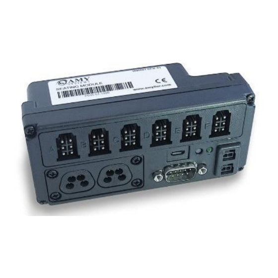
4.1.5.1.3 Verifying R-Net bus cables, actuator cables and intermittent problems • Verify that all cables are properly connected and well secured as shown below. R-Net bus cable connection... - Page 34 Actuator cable connection • Check the condition of the connector terminals by examining that all connections are secure. Verify that there are no traces of oxidation or verdigris on the terminals, that there are no crooked or broken terminals, etc. Check that the cable sheath is not damaged, broken or burnt. •...
-
Page 35: Replacing Pushbuttons In Keypad (Swkeypad)
3. Replacement pushbuttons 4. Cutters 5. Tie-wraps 1. Cut ties securing keypad. REPLACING 2. Remove keypad from mount PUSHBUTTONS using 2.5 mm Allen key. 3. Disconnect keypad from e-bx. 4. Using the Phillips #2 screwdriver, unscrew and remove 4 screws for cover. - Page 36 Ties should be attached in the place they were before. This completes the e-bx controller Instruction Guide. If further information is required, please contact Amylior Technical Support by email at techsupport@amylior.com or by phone at 1 888 453-0311...
Need help?
Do you have a question about the E-BX and is the answer not in the manual?
Questions and answers