
Related Manuals for Amylior LOGOSILVER OUTCHAIR S


Summary of Contents for Amylior LOGOSILVER OUTCHAIR S
- Page 1 You can find this notice on www.logo-silver.fr OUTCHAIR - S AND L MODELS THE ALL-TERRAIN CHAIR.
-
Page 2: Table Of Contents
SUMMARY INTRODUCTION ......................1.1. ABOUT THIS MANUAL ..................... 6 1.2. USE IN ACCORDANCE WITH INSTRUCTIONS ..........7 1.3. LIABILITY ........................7 1.4. INDICATIONS FOR REUSE OF THIS PRODUCT ..........7 1.5. MAINTENANCE ......................8 1.6. CONTACT ........................8 II. SAFETY ..........................2.1. - Page 3 VII. USE ............................22 7.1. “OUTDOOR” DRIVING PROFILE ................23 7.2. “CROSSING” DRIVING PROFILE ................24 7.3. “INDOOR” DRIVING PROFILE WITH CASTER OPTION....... 25 7.4. MANUAL MOVEMENT ....................26 7.5. ADJUSTMENT OPTIONS ..................27 7.5.1. ARMREST ADJUSTMENT ................... 27 7.5.2. MANUAL FOOTRESTS ....................28 7.5.3.
- Page 4 SUMMARY 7.8.7. JOYSTICK LCD......................36 7.8.8. JOYSTICK CJSM2-BT (OPTIONAL) ................ 40 7.8.9. LOCKING THE CONTROL SYSTEM..............47 7.8.10. SCREEN .......................... 48 7.9. DRIVING TIPS ....................... 49 7.10. BATTERIES AND RECHARGING ................49 7.10.1. BATTERIES ........................49 7.10.2. CHARGING THE BATTERIES ................... 50 7.10.3.
- Page 5 10.2. PROTECTION AGAINST CORROSION ............... 59 10.2.1 PEELING PAINT ......................60 10.2.2 BEACH, SALT WATER AND COASTAL AREAS ............ 60 10.2.3 SNOW AND ICE, SALT ROADS AND PATHS ............60 10.2.4 CLEANING AFTER USE....................60 10.2.5 PREVENTATIVE CARE ....................61 10.3.
-
Page 6: Introduction
I. INTRODUCTION 1.1. ABOUT THIS MANUAL First of all, we would like to thank you for your confidence in our products. We hope that your new 4x4 electric wheelchair will bring you a lot of satisfaction. This Owner’s Manual provides the user and attendant with all the necessary knowledge regarding the safety, use, construction, and maintenance of the OUTCHAIR. -
Page 7: Use In Accordance With Instructions
1.2. USE IN ACCORDANCE WITH INSTRUCTIONS The OUTCHAIR is intended for the individual use of persons with total or partial motor disability of the lower limbs, providing a safe driving performance for their independent movement outside the home. The OUTCHAIR must only be associated with the features mentioned in these instructions for use and vice versa. -
Page 8: Maintenance
1.5. MAINTENANCE The maintenance manual contains a schedule of maintenance operations to be carried out for each model as well as detailed information and the list of necessary tools. NOTES Overhaul and repair of the OUTCHAIR must only be performed by qualified personnel approved by Logo Silver. -
Page 9: Declaration Of Conformity
2.2. DECLARATION OF CONFORMITY As a manufacturer, Logo Silver declares under its own responsibility that the OUTCHAIR complies with specifications 93/42 and 2007/47 relative to the European directives for medical devices. The design, development and manufacture of the OUTCHAIR are in full compliance with safety with the following technical requirements: •... -
Page 10: Safety Requirements For Transportation, Storage And Assembly
• Do not go out unaccompanied or without a means of reaching someone you trust for journeys in isolated areas or when the weather conditions are very bad. • The cushion and the backrest fabric are not easily flammable but can catch fire. The use of fire or a lit cigarette should be exercised with extreme caution. -
Page 11: Operation And Safety Requirements
• It is forbidden to travel seated in the OUTCHAIR during transport. • Avoid loading the wheelchair into a vehicle with the driver still in the chair. DANGER ! If the wheelchair needs to be loaded in with its driver via a ramp, an attendant must stand by the wheelchair to avoid it tipping over. - Page 12 • Do not cross over obstacles greater than 4 cm when driving uphill and downhill. • The OUTCHAIR can be driven on ascents and descents of 10 °. • For safety reasons, when driving on a descent greater than 5 °, reduce the speed to 5km / h, avoid braking suddenly and have a seat inclination of 10 °...
- Page 13 DANGER ! Defective brakes can cause serious accidents and injuries that can put the user’s life at risk. DANGER ! If any errors, faults or other hazards that could cause personal injury are detected, the OUTCHAIR must be taken out of service immediately.
-
Page 14: Safety Tips For 2 Wheel Drive With Casters (If Option Available)
• Charging batteries can produce short circuits. Therefore, the following safety precautions must be taken: chair must be off (joystick and reinforced circuit breaker off). • Check the function of the front wheel shock absorbers. Regarding the tyres, the following observations must be taken into account: •... -
Page 15: Care And Disposal
• Remove the casters as far as they will go so that the caster supports are perpendicular to the floor. • Check that the front wheels are no longer turning and do not touch the ground. • It is advisable to lock the right-hand drive if you have chosen the additional steering lock option. -
Page 16: User Requirements
2.8. USER REQUIREMENTS • The use of the OUTCHAIR is reserved for competent users. For this reason, the user must be instructed by qualified and authorized Logo Silver personnel on how to operate the OUTCHAIR. • The user must have read and understood this manual completely. •... -
Page 17: Warning Plates And Nameplates
2.10. WARNING PLATES AND NAMEPLATES 7 rue du Fossé Blanc 92230 Gennevilliers / France • Reference REF: OUTCHAIR • Series number SN:0000001 02/2019 • Date of manufacture • CE marking • Maximum user weight • Maximum lateral slope 140 kg max. 10°... -
Page 18: Technical Features
III. TECHNICAL CHARACTERISTICS OUTCHAIR S OUTCHAIR L Accessibility interior and exterior, all-terrain Configuration 4 wheel drive General dimensions length: 1000 mm with legrests 1100 mm without legrests width: 680 mm height: 1430 mm Seat height from 550 to 610 mm Seat width from 380 to 610 mm Seat depth... -
Page 19: Product Description
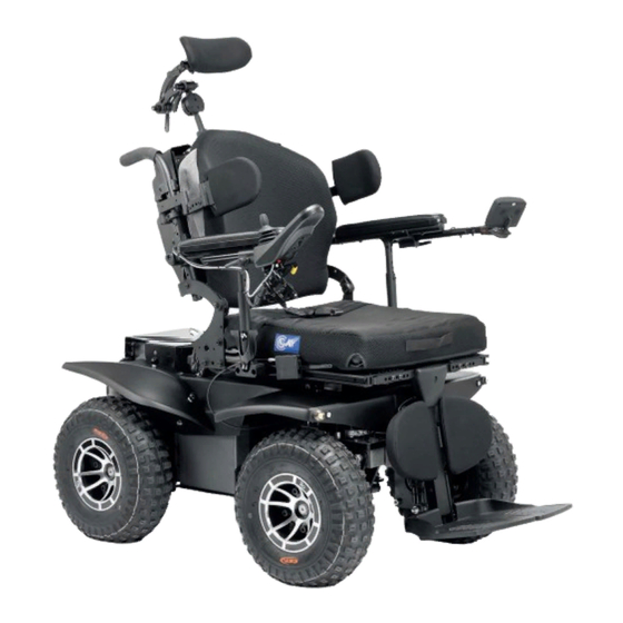
IV. PRODUCT DESCRIPTION The OUTCHAIR is a compact all-terrain power wheelchair. Highly efficient and with great crossing ability, it is ideal for roaming over uneven terrain, in the forest, on the sand, in the snow... It will accompany you everywhere in your daily life, on your nature outings and your sports activities. -
Page 20: Transport And Storage
The main components of the OUTCHAIR: Backrest Headrest Joystick controller Unlock backrest Armrests Lumbar adjustment button Seat Angle adjustment of backrest Motor release levers Footrests Drive wheels Casters (L optional) Fig. 1 V. TRANSPORT AND STORAGE DANGER! Risk of injury in the event of improper transport! DANGER! Under no circumstances can the seat of the OUTCHAIR be used as a seat during transport. -
Page 21: Delivery And Setup
The OUTCHAIR must be strapped to the vehicle’s anchorage points on the trailer or transport vehicle with front and / or rear protection (Fig. 2 et 3). The joystick must be turned off and the engine brakes locked. Fig. 2 Fig. -
Page 22: Initial Charging And Setup
6.2. INITIAL CHARGING AND SETUP Before setup, recharge the batteries with the help of the charger provided by connecting the power cord to the front of the joystick for a minimum of 5 hours, the charger indicators must be green (they can also be orange: completely dead or moderately low). See charging details in chapter 7.10 Batteries and recharging. -
Page 23: Outdoor" Driving Profile
7.1. «OUTDOOR» DRIVING PROFILE WARNING! Take account of the recommendations in Part 2. Safety The maximum speed permitted is 10 km / h. WARNING! Pay particular attention on flat ground or when climbing, the seat should be positioned as parallel to the ground as possible and the back as perpendicular as possible. -
Page 24: Crossing" Driving Profile
7.2. «CROSSING» DRIVING PROFILE This procedure should only be used in case you have to cross over occasional obstacles of more than 4 cm high (sidewalks, bumps, branches ...). WARNING! Take account of the recommendations of Part 2. Safety. Do not attempt to use the off-road or indoor driving profile with speeds of greater than 3 km / h for obstacles greater than 4 cm. -
Page 25: Indoor" Driving Profile With Caster Option
• Be careful as the incline of the seat must be as parallel to the ground as possible and the incline of the backrest must be as perpendicular to the ground as possible. This will avoid any risk of tipping backwards when crossing the front wheels over the obstacle. •... -
Page 26: Manual Movement
9. The speed limit is now disabled, and the front wheels will once again be powered (4-wheel drive). If this is not the case, refer to section 10.5. Caster (optional) malfunction. 10. You can now use the off-road or crossing profile suitable for 4WD. WARNING! Take account of the recommendations in part 2. -
Page 27: Adjustment Options
The wheelchair motors are equipped with magnetic brakes that prevent the wheelchair from rolling on its own when it is at a standstill. The engine brakes are automatically tightened when the joystick is in the neutral or “off” position. To push the wheelchair, disengage the magnetic brakes. -
Page 28: Manual Footrests
7.5.2. Manual footrest 1 - Length adjustment Fig. 8 2 - Angle adjustment 7.5.3. Backrest and headrest 1 - Folding backrest 2 - Lumbar adjustment 3 - Headrest height Fig. 9 Fig. 10 7.5.4. Shock absorber The A5RR1 shock absorbers can be adjusted via two ATV type valves. The upper valve (MP) must be set to between 100 and 150 PSI (not to exceed 180 PSI), this is the main pressure damping that allows for adjustment of the depression of the damper. -
Page 29: Pneumatic Pressure
Recommended main pressure (MP) Secondary pressure (NP) 7.5.5. Tyre pressure The tyre pressure needs to be adjusted according to the terrain. In off-road (bumpy ground, uneven surfaces, fields, path, mud, sand, snow ...) it is recommended to adjust to a low pressure (between 0.4 and 0.5 bar), this will mean a greater comfort of use. -
Page 30: Seat Tilt
Tyre Description Recommended off-road Maximum tyre pressure operating pressure according to their capacity All tyres Black, 5 psi (38 kPa) 24 psi low pressure, Max 7 psi (48 kPa) 165 kPa serrated Recommended tyre pressure on asphalt Recommended tyre pressure on asphalt depending on user weight (Metric system) depending on user weight (Imperial system) 7.5.6. -
Page 31: Joystick Position
Fig. 13 Fig. 14 Fig. 16 Fig. 17 Fig. 15 7.5.8. Joystick positions (Fig. 16 et 17) The joystick is mounted on a pantograph that can be folded backwards and to the side of the armrest to position it near a table, for example. 7.5.9. -
Page 32: Transferring Into The Chair
7.6. TRANSFER INTO THE CHAIR DANGER ! Switch off the joystick (lights off), and make sure that the engine brakes are engaged. • The retractable armrests of the chair allow for lateral transfer. To do this, unscrew the armrest height adjustment knob (16) in order to remove it. If you make the transfer on the joystick side, consider unhooking the joystick cable (17) before removing the armrest. -
Page 33: Switching The Power On And Off
7.7. SWITCHING ON AND OFF DANGER ! Danger of death in case of malfunction of the engine brakes. When using the OUTCHAIR the engine brakes must be engaged and in working order. 7.7.1. Electronic system protection The chair’s electronic control system is equipped with a current control device to prevent circuit damage in the event of overload. -
Page 34: Switching The Power On
7.7.3. Switching on The electronic system will turn on if: • The circuit breaker is armed (if model with circuit breaker) • The joystick is on • The electromagnetic brakes must be engaged otherwise the wheelchair will not move 7.7.4. Switching off •... -
Page 35: Joystick Cable
7.8.4. Joystick cable If, for any reason the joystick cable is disconnected, be careful not to force it back in again. The plug is polarized and can only be inserted in one direction. WARNING! Do not insert the plug in the wrong direction, as this may cause irreparable damage to the electronic system. -
Page 36: Joystick Lcd
7.8.7. LCD joystick Joystick Charger socket External switch jacks Communication cable CONTROL PANEL With lighting Without lighting LCD screen Symbol Control Description This button turns the R-net control system on and off. Do not use this button to stop the Power chair, except in case of emergency. - Page 37 7.8.7.1. LCD screen control system Indicators The colored LCD screen is divided into three information zones: 1 - Top bar 2 - Main screen area 3 - Base bar Area Symbol Indication Description Displays the available charge on the battery and Battery indicates the status of the battery.
- Page 38 Symbol Indication Description Displays the sections of the chair selected for movement. Action Mode When Bluetooth mode is enabled, the following screen Bluetooth mode is displayed. The R-net Control System displays warning icons and Message Window informational messages in an allocated message window. The control system requires a restart.
- Page 39 7.8.7.2. Basic programming and configuration Basic programming can be performed by simultaneously pressing and holding the increase / decrease buttons. This will take you to the Settings menu : Adjusting the time: • Shift the joystick once to the right to open the clock settings. Set the time using the joystick.
-
Page 40: Joystick Cjsm2-Bt (Optional)
7.8.8. Joystick CJSM2-BT (optional) Symbol Control Description Activated by pushing the left switch forward. On / Off Selects available driving profiles and operating Profile/Mode modes by pulling the left switch backward. Sets the system speed setting. Speed This button activates the wheelchair hornt. Horn The Mode button allows the user to browse Mode... - Page 41 7.8.8.1. Indications on the control system screen The color LCD is divided into four areas of information: 1 - Battery indicator 2 - Information icons 3 - Main area 4 - Base bar Without lighting control With lighting control Area Symbol Indication Description...
- Page 42 Area Symbol Indication Description Digital Speed Displays the actual speed of your wheelchair. Displays the total distance travelled by the chair, Odometer or the distance travelled since the last reset. The wheelchair speed is limited. Limited speed The wheelchair drive is inhibed. Inhibition The control system is lock.
- Page 43 7.8.8.2. Basic programming and setup Press and hold the button in the upper left corner of the screen (Danger button) for 1 second. This action will display the menu: Adjusting the time: • Setting the time: shift the joystick once to the right to open the clock setting. Set the time using the joystick.
- Page 44 7.8.8.4. Pairing the CJSM-BT Enter the «CJSM2 Setup» menu and select «Bluetooth». The names of the preprogrammed devices should appear. Logo-Silver has preprogrammed the following devices: • iPad • iPhone • PC • Android device: Press and hold the top left screen button (Danger button) for 1 second to enter the settings menu.
- Page 45 Disabling connected devices: To turn off a connected device and delete it from the menu displayed in «My devices», select «Bluetooth» in the settings menu. The devices can be disabled by pushing the joystick to the right. Note: It is not necessary to pair the device again if it is turned on at a later stage. 7.8.8.6.
- Page 46 IR Setup (IR configuration): The «IR Setup» menu is accessible from the «Settings Menu». When you enter the «IR Setup» menu, the default devices are displayed. Select a device to display its commands. If a command is checkmarked, it means that an IR code has been stored. If there is no checkmark, no IR code has been saved for this command.
-
Page 47: Locking The Control System
• Point the television remote control at the CJSM2-BT Receiver LED and press the «On / Off» button twice. • After each successful instruction, a check mark appears momentarily on the screen, select «Learn Code» to add a new code to the sequence or «Exit» if the sequence is complete. -
Page 48: Screen
• Release the joystick, a long beep will sound. • The chair is now unlocked. Locking with the key: Once the control system has been turned on, insert and remove the supplied PGDT key from the charger jack on the joystick module. A short beep will sound. The wheelchair is now locked. -
Page 49: Driving Tips
7.9. DRIVING TIPS The OUTCHAIR can be driven on climbs and descents of 10°. In order to guarantee a safe downhill descent, it is necessary to reduce speed depending on the gradient and to avoid sudden braking. In order to guarantee a safe climb, reduce speed and do not accelerate too hard. Obstacles must be cleared at reduced speed. -
Page 50: Charging The Batteries
car batteries, these are different. Car batteries are not designed for long and deep discharge, and their use in electric chairs could be dangerous. WARNING! The battery terminals and their accessories contain lead, wash your hands after handling them. WARNING! Batteries contain corrosive chemicals. -
Page 51: Charging Process
• Fully charge the chair at night, checking that the charger indicates that the battery is fully charged (switches to charge maintenance mode). • Repeat steps 2 and 3 the first 20 times (cycles) to complete the «break-in» procedure. NOTES The battery capacity is limited when it is new, this is perfectly normal, and this will improve during the breaking-in process. - Page 52 • Once the batteries are empty, recharge them completely (this may take more than eight hours). • Protect the charger from moisture and extreme temperatures. • Avoid placing the charger near a heat source such as a radiator or exposing it directly to sunlight.
-
Page 53: Battery Gauge
7.10.5. Battery gauge on the LCD screen The batteries are charged if the battery gauge reads red, yellow and green. You need to charge the batteries as soon as you can if the battery gauge only indicates red and yellow. You must charge the batteries immediately if the battery gauge only indicates a steady or slowly flashing red. -
Page 54: Options
VIII. OPTIONS 8.1. JOYSTICK CJSM2 WITH BLUETOOTH See chapter 7.8.8. CJSM2-BT joystick. 8.2. RAISED POWER LEGRESTS Raised power legrests are controlled via the joystick by pressing the mode button. When you are in the mode screen you can control: • The raising and lowering of both legrests by pressing right or left on the joystick to select the “leg raise”... -
Page 55: Casters
• To lock the steering, first put the front wheels as straight as possible and pull the lever upwards. • To unlock the steering; push the lever down and shift it to the side to prevent it from moving. 8.4. CASTERS This option is only available with the OUTCHAIR L (Long). -
Page 56: Other Optional Components
8.7. OTHER OPTIONAL ELEMENTS The other options or adjustments will be added to this notice as a related addendum in this chapter. IX. MALFUNCTION AND TROUBLESHOOTING 9.1. DIAGNOSIS AND TROUBLESHOOTING Electronic repairs should only be carried out by authorized service providers. Improper or incorrect repair can result in an unsafe adjustment to the wheelchair. -
Page 57: Solving Common Problems
The activation of one of these switches affects the driving performance of the chair. Return the seat to its upright position, make sure that the seat incline is horizontal, retract the casters and check that the problem is resolved. 9.2. SOLVING COMMON PROBLEMS Problems Diagnostic Solving... -
Page 58: Maintenance And Care
X. CARE AND MAINTENANCE 10.1. GENERAL RECOMMENDATION NOTES The OUTCHAIR should be checked once a year by qualified staff approved by Logo Silver. Only Logo Silver spare parts can be used. Failure to comply with this condition results in the loss of warranty rights. -
Page 59: Protection Against Corrosion
WARNING! Direct exposure to rain or moisture will cause electrical and mechanical malfunctions and risks rusting the chair prematurely. • Avoid exposing your electric wheelchair to moisture (rain, snow, fog, salt water or cleaning products). Such exposure could damage your chair - see section 10.2. Protection against corrosion. -
Page 60: Peeling Paint
The most common causes of corrosion of the electric wheelchair are: • Paint or undercoat peeling caused by impacts from stones and other hard objects. • Accumulation of salt, soil and moisture on the frame components. • Exposure to highly corrosive environments such as seaside, rivers and streams; 10.2.1. -
Page 61: Preventative Care
10.2.5. Preventative Maintenance Before using your chair in a moist or corrosive environment, it is advised you protect it by carefully coating all metal surfaces with a waterproofing product. This product may for example be an oil-based aerosol (such as WD40) or a lanolin-based dispersant (such as Lanotec). -
Page 62: Weekly Checks
10.4. WEEKLY CHECKS Parts Verifications Electric brakes This test must be performed on a flat surface with at least one gauge of free space around the chair. • Turn on the control system. • Check that the battery gauge stays on or flashes slowly after one second. -
Page 63: Monthly Checks
10.5. MONTHLY CHECKS Parts Verifications Armrests and lateral • Check the fasteners. sections • Check that the armrests can be adjusted without excessive effort. • Check that the armrests are locked in place. Legrests • Check that the legrests click into place properly. •... -
Page 64: Repair Of A Tire And / Or An Inner Tube
10.7. REPAIR OF A TIRE AND / OR AN INNER TUBE NOTE Direct exposure to sunlight (UV) accelerates tyre aging. Regardless of their wear, the tyres must be changed every 2 years. Tools: • A Hexagonal Allen key, 8 mm •... - Page 65 Wheel assembly: The assembly is carried out in reverse order. Make sure that the wheel is remounted on the same side and in the same direction as it was during disassembly. • Tighten 4 screws to 30 Nm • Tighten both locknuts on two of the four screws indicated at Fig. 26. WARNING! If a wheel is not tight enough during assembly and / or the locknuts are not in place it may come off during a movement and cause injury.
-
Page 66: Battery Replacement
10.8. BATTERY REPLACEMENT Tools: • A pair of pliers • 2 flat 17” wrenches • A 6 mm BTR wrench • An 11” wrench • 1 shim • A 8 mm BTR wrench • 2 flat 10” wrenches • A 5 mm BTR wrench •... -
Page 67: Battery Removal
10.8.1. Battery removal • Disarm the circuit breaker; • On the OUTCHAIR L, remove the two rear mudguards by unscrewing the mudguard screws. (Fig. 27) • On the OUTCHAIR S, remove the complete/full body/bodywork by unscrewing the four knobs and tilting the seat. (Fig. 28) •... -
Page 68: Reassembling The Batteries
10.8.2. Battery reassembly This is the opposite operation taking care to connect the cables as they were before disassembly; 10.9. SEAT TILT MALFUNCTION • Every month it is important to check that the two bump stops are in good condition and they are both in contact when the seat incline is at its maximum. -
Page 69: Caster (Optional) Malfunction
10.10. CASTER (OPTIONAL) MALFUNCTION • If the front wheels rotate while the casters are out, the left switch may be disconnected and / or incorrectly adjusted. It is also possible that the relays need to be changed. • If the speed limit is at 3 km / h when your casters are fully retracted, it is possible that the right switch is disconnected and / or incorrectly adjusted. -
Page 70: Steering Lock (Optional) Malfunction
10.11. STEERING LOCK (OPTIONAL) MALFUNCTION If you notice that the steering lock is not effective enough you can adjust the cable tension by turning the adjustment dial on the control. If this adjustment of the cable tension does not allow the steering lock to be adjusted correctly, you must: •... -
Page 71: Warranty
DANGER ! When cleaning the OUTCHAIR, water should not come into contact with electronic components and batteries. Do not use aggressive cleaning agents, solvents or hard brushes. Risk of damage to the electronic system! Risk of malfunction! XI. GARANTIE The wheelchair is guaranteed for 2 years from the date of delivery, excluding corrosion, normal wear of parts (tyres etc.), abnormal use, usage which does not comply with the instructions of use. -
Page 72: Disposal
Warning signs and signals 7 rue du Fossé Blanc 92230 Gennevilliers / France • Reference REF: OUTCHAIR L • Serial number SN:0000001 02/2019 • Date of manufacture • CE mark • Maximum user weight 140 kg max. 10° max. • Maximum slope/ gradient XII. - Page 73 P·73...
- Page 74 P·74...
- Page 75 P·75...
- Page 76 Logo Silver www.logo-silver.fr 32 rue de Comboire - 38130 Echirolles - France Tél. +33(0)4 76 21 22 19 - contact@logo-silver.fr...
Need help?
Do you have a question about the LOGOSILVER OUTCHAIR S and is the answer not in the manual?
Questions and answers