
Related Manuals for Lenze EMF2133IB


Summary of Contents for Lenze EMF2133IB
- Page 1 EDSMF2133IB L−force Communication .G÷h Communication Manual PROFIBUS−DP EMF2133IB Communication module...
-
Page 2: Table Of Contents
Contents About this documentation ..........Document history . - Page 3 ............Lenze device control .
- Page 4 ....... 8.2.2 Addressing of the Lenze parameters ......
-
Page 5: About This Documentation
This documentation is intended for all persons who plan, install, commission and maintain the networking and remote service of a machine. Tip! Information and auxiliary devices around the Lenze products can be found in the download area at http://www.Lenze.com EDSMF2133IB EN 5.0... -
Page 6: Document History
These instructions were created to the best of our knowledge and belief to give you the best possible support for handling our product. If you have suggestions for improvement, please e−mail us to: feedback−docu@Lenze.de Thank you for your support. Your Lenze documentation team EDSMF2133IB EN 5.0... -
Page 7: Conventions Used
About this documentation Conventions used Conventions used This documentation uses the following conventions to distinguish between different types of information: Type of information Identification Examples/notes Spelling of numbers Decimal separator Point In general, the decimal point is used. For instance: 1234.56 Decimal Standard notation For example: 1234... -
Page 8: Terminology Used
The term stands for the PROFIBUS−DP variant according to IEC 61158 / IEC 61784. A different PROFIBUS variant is not described in these Instructions. Standard device Lenze controllers/frequency inverters with which the communication module can be used. Controller ^ 12... -
Page 9: Notes Used
About this documentation Notes used Notes used The following pictographs and signal words are used in this documentation to indicate dangers and important information: Safety instructions Structure of safety instructions: Danger! (characterises the type and severity of danger) Note (describes the danger and gives information about how to prevent dangerous situations) Pictograph and signal word Meaning... -
Page 10: Safety Instructions
The manufacturer does not accept any liability for the suitability of the specified procedures and circuit proposals. Only qualified skilled personnel are permitted to work with or on Lenze drive and ƒ... -
Page 11: Device− And Application−Specific Safety Instructions
Safety instructions Device− and application−specific safety instructions Device− and application−specific safety instructions During operation, the communication module must be securely connected to the ƒ standard device. With external voltage supply, always use a separate power supply unit, safely ƒ separated in accordance with EN 61800−5−1 in every control cabinet ("SELV" / "PELV"). -
Page 12: Product Description
Product description Application as directed Product description Application as directed The communication module ... is an accessory module which can be used in conjunction with the following Lenze ƒ standard devices: Device type Design Version Variant Explanation 82EVxxxxxBxxxXX 8200 vector... -
Page 13: Identification
Product description Identification Identification 1D74 Type Id.-No. Prod.-No. Ser.-No. Input E82AF000P0B201XX 9371BC019 W 33.2133IB Series Hardware version Software version EDSMF2133IB EN 5.0... -
Page 14: Product Features
ƒ fails DIP switches for ... ƒ – Setting of the node address – Setting of the compatibility to the Lenze PROFIBUS communication module EMF2131IB LED status displays: ƒ – Voltage supply of the communication module – Connection from the communication module to the PROFIBUS network –... -
Page 15: Connections And Interfaces
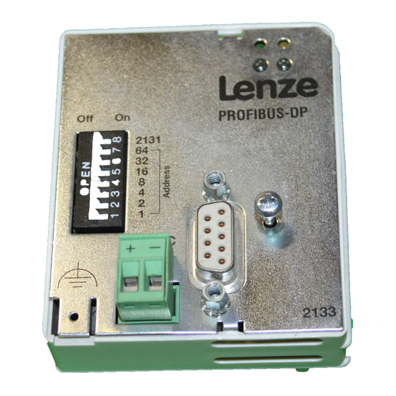
EMF2133IB PROFIBUS DP 2131 24V DC 2133 2133PFB003 2102LEC007 Fig. 3−1 EMF2133IB communication module (PROFIBUS−DP) Pos. Description Detailed information Status of the voltage supply (green LED) ^ 112 Status of the PROFIBUS communication (yellow LED) Operating status of the standard device (red/green LED) DIP switches for setting the ... -
Page 16: Technical Data
V = +24 V DC ±10 % I = 120 mA Documentation for Lenze series of devices 8200 vector, 9300 and ECS Here you can find the ambient conditions and the electromagnetic compatibility (EMC) specifications applying to the communication module. -
Page 17: Protective Insulation
Protective insulation Protective insulation Danger! Dangerous electrical voltage If Lenze controllers are used on a phase earthed mains with a rated mains voltage ³ 400 V, protection against accidental contact is not ensured without implementing external measures. Possible consequences: Death or serious injury ƒ... -
Page 18: Communication Time
Technical data Communication time Processing time 820X Communication time The communication time is the time between the start of a request and the arrival of the corresponding response. The communication times depend on ... the processing time in the controller ƒ... -
Page 19: Processing Time 821X / 822X / 824X / 8200 Vector
Technical data Communication time Processing time 821X / 822X / 824X / 8200 vector 4.3.2 Processing time 821X / 822X / 824X / 8200 vector Parameter data Process data 30 ... 50 ms 2 ... 3 ms 4.3.3 Processing time 93XX / ECSxS There are no interdependencies between parameter data and process data. -
Page 20: Dimensions
Technical data Dimensions Dimensions PROFIBUS DP 2131 24V DC 2133 2133PFB003 61 mm 75 mm 28 mm 18 mm EDSMF2133IB EN 5.0... -
Page 21: Installation
Installation Installation Danger! Inappropriate handling of the communication module and the standard device can cause serious personal injury and material damage. Observe the safety instructions and residual hazards described in the documentation for the standard device. Stop! Electrostatic discharge Electronic components of the communication module can be damaged or destroyed through electrostatic discharge. -
Page 22: Mechanical Installation
Installation Mechanical installation Mechanical installation 2102LEC014 Fig. 5−1 Attaching the communication module Plug the communication module onto the standard device (here: 8200 vector). ƒ Tighten the communication module to the standard device using the fixing screw in ƒ order to ensure a good PE connection. Note! For the internal supply of the communication module by the 8200 vector frequency inverter the jumper has to be adjusted within the interface opening... -
Page 23: Electrical Installation
Installation Electrical installation Wiring according to EMC (CE−typical drive system) Electrical installation 5.2.1 Wiring according to EMC (CE−typical drive system) For wiring according to EMC requirements observe the following points: Note! Separate control cables/data lines from motor cables. ƒ Connect the shields of control cables/data lines at both ends in the case of ƒ... -
Page 24: Wiring With A Host (Master)
Installation Electrical installation Wiring with a host (master) 5.2.2 Wiring with a host (master) Danger! You have to provide additional electrical isolation if ... an 820X and 821X controller is connected to the host and ƒ a safe electrical isolation (reinforced insulation) according to EN 61800−5−1 ƒ... - Page 25 Installation Electrical installation Wiring with a host (master) Number of bus devices 2133PFB004 Segment Master (M) Slave (S) Repeater (R) − − − − Tip! Repeaters do not have a device address. When calculating the maximum number of bus devices, they reduce the number of devices by 1 on each side of the segment.
- Page 26 Installation Electrical installation Wiring with a host (master) Bus cable length The length of the bus cable depends on the baud rate used: Baud rate [kbps] Length [m] 9.6 ... 93.75 1200 187.5 1000 1500 3000 ... 12000 Note! The baud rate depending on the data volume, cycle time, and number of nodes should only be selected as high as required for the application.
-
Page 27: Connection Of The Profibus
Installation Electrical installation Connection of the PROFIBUS 5.2.3 Connection of the PROFIBUS The PROFIBUS network is connected via the 9−pole Sub−D socket. View Designation Description − − − − RxD/TxD−P Data cable B (receive / send data plus) Request To Send (receive / send data, no differential signal) M5V2 Data reference potential (ground to 5V) -
Page 28: Voltage Supply
For internal voltage supply place the jumper on the position indicated ƒ below. In the case of all other device series (9300, ECS), voltage is always supplied from the standard device. Lenze setting Internal voltage supply (Only external voltage supply possible.) EDSMF2133IB EN 5.0... - Page 29 Installation Electrical installation Voltage supply External voltage supply Note! Always use a separate power supply unit in every control cabinet and safely separate it according to EN 61800−5−1 ("SELV"/"PELV") in the case of external voltage supply and larger distances between the control cabinets. External voltage supply of the communication module is required if communication via the fieldbus is to be maintained even when the power supply of the standard device fails.
-
Page 30: Cable Cross−Sections And Screw−Tightening Torques
Installation Electrical installation Cable cross−sections and screw−tightening torques 5.2.5 Cable cross−sections and screw−tightening torques Area Values Electrical connection Plug connector with screw connection Possible connections rigid: 1.5 mm (AWG 16) flexible: without wire end ferrule 1.5 mm (AWG 16) with wire end ferrule, without plastic sleeve 1.5 mm (AWG 16) with wire end ferrule, with plastic sleeve... -
Page 31: Commissioning
In addition to these configuration codes, there are codes for diagnosing and monitoring the bus devices. The codes can be set e.g. via an operating module (keypad) or a PC with the Lenze parameter setting program »Global Drive Control« (GDC). -
Page 32: Initial Switch−On
Select process data communication with DRIVECOM profile in the configuration software of the PROFIBUS master. Example: "Par(kons)+3PZD" ^ 34 Configure host system for communication with the EMF2133IB communication module. Inhibit standard device via terminal. Documentation of the standard device ^ 37 Check bus termination. - Page 33 Commissioning Initial switch−on Step Procedure Detailed information It is now possible to communicate with the controller, i.e. exchange process data (setpoints and actual values); read all codes; change all codes that can be written. See the attribute table or code description of the corresponding standard device.
-
Page 34: Configuring The Host System (Master)
Tip! The GSE file can be downloaded in the "Services & Downloads" area at www.Lenze.com. Device data base file (GSE) The following configurations can be found in the device data base files Lenz2133.GSD (DP−V0) and Len_2133.GSD (DP−V1):... - Page 35 6 words 6 words n = 1 ... 12 Example of the selection text of the device data base file PAR (Cons) PCD (7W) Lenze device control Process data words (7 words) Parameter data channel (4 bytes consistent) PAR (Cons) PCD (8W) Without "AR": Control with DRIVECOM−Profil...
- Page 36 Commissioning Configuring the host system (master) Defining the user data length The user data length is defined during the initialisation phase (configuration). Up to 12 process data words can be configured (depending on the basic device used). Optionally you can activate the parameter data channel. If the parameter data channel is active, it additionally occupies 4 words of the process data inputs and outputs.
-
Page 37: Activating The Bus Terminating Resistor
– the connector has been disconnected e.g. in service case; – the voltage supply of the communication module has been switched off. Setting the software compatibility Note! If the EMF2131IB communication module is replaced by the EMF2133IB communication module, ... do not change any host settings; ƒ... -
Page 38: Preparing The Standard Device For Communication
Frequency inverter 82XX / 8200 vector Step Procedure Detailed information ^ 46 In order that you can operate the controller via PROFIBUS, set the Lenze parameter "Operating mode" C0001 = 3. Documentation of Example of PROFIBUS Write: the standard device C0001=3 Index = 0x5FFE (resulting from 0x5FFF −... -
Page 39: 93Xx Servo Inverter / 9300 Servo Plc
^ 46 93XX In order that you can operate the controller via PROFIBUS, set the Lenze parameter "Signal configuration" C0005 = xxx3. When commissioning for the first time, we recommend to select Documentation of the signal configuration "1013" (speed control). -
Page 40: Drive Plc
Commissioning Preparing the standard device for communication Drive PLC 6.6.3 Drive PLC Step Procedure Detailed information ^ 46 Implement the system blocks AIF−IN1 ... 3, AIF−OUT1 ... 3 and, if available, the AIF management into the control configuration of the IEC61131 project. Documentation of The controller can now accept control and parameter setting data via the the standard device... -
Page 41: Axis Modules Ecsxs / Ecsxa
Axis modules ECSxS / ECSxA Step Procedure Detailed information ^ 46 ECSxS Set the Lenze parameter "Control mode": C3005 = 1003 (setpoint via AIF, speed−controlled) Documentation of C3005 = 4003 (setpoint via AIF, torque−controlled) the standard device Example of PROFIBUS Write: C3005=1003 (speed control) Index = 0x5442 (resulting from 0x5FFF −... -
Page 42: Setting The Node Address
Valid address range: 3 … 126 (Lenze setting: 126, provided that C0009 = 1) 6.7.1 Setting via code DIP switches S1 ... S7 = OFF (Lenze setting) ƒ Set the node address via the standard device code C0009 (e.g. via keypad or »Global ƒ... -
Page 43: Settings By A Master (Class 2)
Mapping to code C0009 1 ... 2 No (master addresses) 3 ... 99 Yes (3 ... 99) 100 ... 125 Yes (C0009 = 2) 126 (LENZE setting) Yes (C0009 = 1) Tab. 6−1 Assignment of station addresses to controllers EDSMF2133IB EN 5.0... -
Page 44: Connecting The Mains Voltage
− in some cases − even not allowed. The restart behaviour of the controller can be set in C0142: C0142 = 0 (Lenze setting) ƒ – The controller remains inhibited (even if the fault is no longer active). -
Page 45: Process Data Transfer
Process data transfer Process data transfer request response 2133PFB008 Fig. 7−1 PROFIBUS process data transfer PROFIBUS transmits parameter data and process data between the host (master) and the controllers connected to the bus (slaves). Depending on their time−critical nature, the data are transmitted via different communication channels. -
Page 46: Lenze Device Control
Process data transfer Lenze device control Setpoint source selection Lenze device control 7.1.1 Setpoint source selection Note! Note that the selection of the setpoint source must be set the same in all parameter sets. 82XX / 8200 vector frequency inverters For these controllers the setpoint source selection is determined under code C0001. -
Page 47: Process Data Signals For 82Xx Frequency Inverters
Process data transfer Lenze device control Process data signals for 82XX frequency inverters 7.1.2 Process data signals for 82XX frequency inverters Process data telegram from drive Byte 1 Byte 2 Byte 3 Byte 4 Status word Actual value High byte... - Page 48 Process data transfer Lenze device control Process data signals for 82XX frequency inverters Device status word AIF−STAT for 82XX (C0150, I−5F69) 820X 821X / 822X / 824X Assignment Assignment Current parameter set Current parameter set Parameter set 1 or 3 active...
- Page 49 Process data transfer Lenze device control Process data signals for 82XX frequency inverters Imax - / fd=fdsoll fd=fdsoll / HLG Qmin fd>0 STAT B11 B10 B9 B8 16 Bit .B10 ... .
- Page 50 Process data transfer Lenze device control Process data signals for 82XX frequency inverters Device control word AIF−CTRL for 82XX (C0135, index 5F78 820X 821X / 822X / 824X Assignment Assignment 0 / 1 JOG values 0 / 1 JOG values...
- Page 51 Process data transfer Lenze device control Process data signals for 82XX frequency inverters 0 1 1 JOG/ C046 0 1 0 1 CINH 16 Bit TRIP-SET .B10 .B11 TRIP-RESET .B12 .B13 .B14 .B15 C0046 16 Bit 2141LON010 Fig. 7−3 Access to control word and frequency setpoint in 82XX (fixed assignment)
-
Page 52: Process Data Signals For 8200 Vector Frequency Inverters
Process data transfer Lenze device control Process data signals for 8200 vector frequency inverters 7.1.3 Process data signals for 8200 vector frequency inverters General Digital and analog input and output signals can be configured freely (see 8200 vector" documentation: codes C0410, C0412, C0417 and C0421). - Page 53 Process data transfer Lenze device control Process data signals for 8200 vector frequency inverters Device status word AIF−STAT for 8200 vector (C0150, index 5F69 Assignment Set under C0417/... (Lenze setting) Current parameter set (DCTRL−PAR−B0) Pulse inhibit (DCTRL1−IMP) limit (MCTRL1−IMAX) Output frequency = frequency setpoint (MCTRL1−RFG1=NOUT)
- Page 54 Process data transfer Lenze device control Process data signals for 8200 vector frequency inverters Process data telegram to drive Byte 1 Byte 2 Byte 3 Byte 4 Byte 5 Byte 6 Control word AIF−IN.W1 AIF−IN.W2 High byte Low byte High byte...
- Page 55 Process data transfer Lenze device control Process data signals for 8200 vector frequency inverters Device control word AIF−CTRL for 8200 vector (C0135, index 5F78 Assignment (Lenze setting) Set under C0410/... C0001 = 3 with C0007 £ 51 C0001 = 3 with C0007 > 51...
- Page 56 Process data transfer Lenze device control Process data signals for 8200 vector frequency inverters AIF-IN C0410/x = 10 C0410/x = 11 C0410/x = 12 DCTRL AIF-CTRL DCTRL 16 Bit CINH TRIP-SET .B10 .B11 TRIP-RESET .B12 C0410/x = 22 .B15 C0410/x = 25 AIF-IN.W1...
-
Page 57: Process Data Signal For 9300 Servo Inverters
Process data transfer Lenze device control Process data signal for 9300 servo inverters 7.1.4 Process data signal for 9300 servo inverters The assignment of the process data for the 93XX controller can be changed by configuring the system blocks AIF−IN and AIF−OUT. - Page 58 Process data transfer Lenze device control Process data signal for 9300 servo inverters Device status word AIF−STAT for 93XX 9300 servo inverter C0005 = 1xx3 C0005 = 4xx3 C0005 = 5xx3 C0005 = 6xx3, 7xx3 DCTRL−PAR1−0 DCTRL−PAR1−0 DCTRL−PAR1−0 DCTRL−PAR1−0 DCTRL−IMP DCTRL−IMP...
- Page 59 Process data transfer Lenze device control Process data signal for 9300 servo inverters 9300 POS 9300 CRV 9300 vector C0005 = 2xxx3 C0005 = xxx3 C0005 = C0005 = 4xx3 C0005 = 6xx3, 7xx3 1xxx, 2xxx, 3xxx, 5xxx, 10xxx, 11xxx Not used CERR1−ERR...
- Page 60 Process data transfer Lenze device control Process data signal for 9300 servo inverters Process data telegram to drive Byte 1 Byte 2 Byte 3 Byte 4 Byte 5 Byte 6 Byte 7 Byte 8 Control word AIF−IN.W1 AIF−IN.W2 AIF−IN.W3 High byte...
- Page 61 Process data transfer Lenze device control Process data signal for 9300 servo inverters Device control word AIF−CTRL for 93XX 9300 servo inverter C0005 = 1xx3 C0005 = 4xx3 C0005 = 5xx3 C0005 = 6xx3, 7xx3 NSET−JOG*1 Not used NSET−JOG*1 Not used NSET−JOG*2...
- Page 62 Process data transfer Lenze device control Process data signal for 9300 servo inverters A I F - I N D C T R L A I F - C T R L . B 3 Q S P A I F - C T R L . B 8 D I S A B L E A I F - C T R L .
-
Page 63: Process Data Signals For 9300 Servo Plc And Drive Plc
Process data transfer Lenze device control Process data signals for 9300 Servo PLC and Drive PLC 7.1.5 Process data signals for 9300 Servo PLC and Drive PLC Process data telegram from the drive Name / variable name Meaning AIF1_wDctrlStat Device status word... - Page 64 Process data transfer Lenze device control Process data signals for 9300 Servo PLC and Drive PLC Outputs_AIF1 Outputs_AIF2 AIF2_nOutW1_a 16 Bit Byte Byte AIF1_wDctrlStat AIF2_bFDO0_b 16 Bit 16 binary signals Byte AIF2_bFDO15_b Byte AIF2_nOutW2_a 16 Bit Byte Byte AIF1_nOutW1_a AIF2_bFDO16_b...
- Page 65 Process data transfer Lenze device control Process data signals for 9300 Servo PLC and Drive PLC Process data telegram to the drive Name / variable name Meaning AIF1_wDctrlCtrl Device control word AIF1_nInW1_a AIF word 1 AIF1_nInW2_a AIF word 2 AIF1_nInW3_a...
- Page 66 Process data transfer Lenze device control Process data signals for 9300 Servo PLC and Drive PLC Inputs_AIF1 Inputs_AIF2 AIF1_wDctrlCtrl 16 Bit AIF1_bCtrlB0_b AIF2_nInW1_a 16 Bit Byte AIF1_bCtrlB1_b AIF1_bCtrlB2_b AIF2_bInB0_b 16 binary AIF1_bCtrlQuickstop_b signals Byte AIF2_bInB15_b AIF1_bCtrlB4_b AIF1_bCtrlB5_b AIF2_nInW2_a AIF1_bCtrlB6_b 16 Bit...
-
Page 67: Process Data Signals For Axis Modules Ecsxs / Ecsxa
Process data transfer Lenze device control Process data signals for axis modules ECSxS / ECSxA 7.1.6 Process data signals for axis modules ECSxS / ECSxA Detailed information ..on the process data transfer for the ECS servo system and the required system... -
Page 68: Drivecom Control
Drivecom Profile 20 is a non−proprietary definition of important parameters and the controller behaviour. Apart from DRIVECOM definitions, there are other Lenze specific functionalities which must be adapted to achieve full compatibility to the DRIVECOM Profile. The device−specific changes are listed in the table below: Controller Device−specific changes... -
Page 69: Drivecom State Machine
DRIVECOM state machine 7.2.2 DRIVECOM state machine For the PROFIBUS control and the use of the EMF2133IB communication module the Lenze controllers feature the standardised device states in accordance with the "Drive technology 20" DRIVECOM profile. Associated preconfiguration of the controllers: 82XX: C0001 = 3 ƒ... - Page 70 Process data transfer DRIVECOM control DRIVECOM state machine 82XX, 8200 vector (C0001 Ø3) For standard device control you enter the control information via the corresponding control inputs (terminal): Information on the current device status (see Fig. 7−11, marked by rectangles) is stored in the DRIVECOM parameter "status word".
-
Page 71: Drivecom Control Word
Process data transfer DRIVECOM control DRIVECOM control word 7.2.3 DRIVECOM control word Name Meaning Switch on 0 = command 2, 6, 8 (controller inhibit) 1 = command 3 (controller inhibit) Voltage inhibit 0 = Voltage inhibit active 1 = Voltage inhibit not active Quick stop 0 = quick stop (QSP) active 1 = quick stop (QSP) inactive... - Page 72 Process data transfer DRIVECOM control DRIVECOM control word Name Meaning Manufacturer 820X Process input data inhibit: Inhibit update of the process output data of the controller (input data for the master). The updating of status and actual information of the process data channel can be inhibited in order to transmit control information more precisely in time.
-
Page 73: Drivecom Status Word
0 = No message 1 = Message (IMP) Remote 82xx / 821x / Bus access right, depending on Lenze parameter "Operating mode" 822x / 8200 (C0001) 0 = C0001 ¹ 3 vector 1 = C0001 = 3... - Page 74 Process data transfer DRIVECOM control DRIVECOM status word Name Description Manufacturer 82xx / 821x / < d Qmin 822x 0 = Q not active 1 = Q active 8200 vector / Mapping to bit C0150.B5 93XX EDSMF2133IB EN 5.0...
-
Page 75: Bit Control Commands
Process data transfer DRIVECOM control Bit control commands 7.2.5 Bit control commands The bit control commands of the control word depend on other bit settings. The command is only executed with the following bit patterns: Device status commands Bits of the control word 1 Standstill 2 Switch on 3 Enable operation... -
Page 76: Status Bits
Process data transfer DRIVECOM control Status bits 7.2.6 Status bits The current device status is clearly coded in bits 0 ... 6 of the status word: Device status Bits of the status word NOT READY TO START SWITCH−ON INHIBIT READY TO START SWITCHED ON OPERATION ENABLED FAULT... -
Page 77: Profidrive Control
The PROFIdrive profile, version 2, is a non−proprietary definition of important parameters and the controller behaviour. Apart from PROFIdrive definitions, there are other Lenze specific functionalities which must be adapted to achieve full compatibility to the PROFIdrive profile. The device−specific changes are listed in the table below: Controller Device−specific changes... -
Page 78: Profidrive State Machine
Process data transfer PROFIdrive control PROFIdrive state machine 7.3.2 PROFIdrive state machine Example: Fault recognised Status information by parameter "status word" bit 15 ... bit 0 (binary representation) Fault reaction active Command / control word: Status word xxxx xxxx x0xx 1111 OFF1 / xxxx x1xx xxxx x110 OFF2 / xxxx x1xx xxxx xx0x Automatically when fault... -
Page 79: Profidrive Control Word
Process data transfer PROFIdrive control PROFIdrive control word 7.3.3 PROFIdrive control word Name Meaning OFF1 0 = OFF1 active; RFG zero, controller inhibit at zero speed 1 = OFF1 inactive OFF2 0 = OFF2 active 1 = OFF2 inactive OFF3 0 = OFF3 active 1 =OFF3 inactive Enable... - Page 80 Process data transfer PROFIdrive control PROFIdrive control word Name Meaning Manufacturer 820X Process input data inhibit Inhibit update of the process output data of the controller (input data for the master). The updating of status and actual information of the process data channel can be inhibited in order to transmit control information more precisely in time.
-
Page 81: Profidrive Status Word
Collective warning 0 = no warning 1 = warning Reserved Always 1 Master 82xx / 821x / Bus access right, depending on Lenze parameter "Operating mode" function 822x / 8200 (C0001) requested vector 0 = C0001 <> 3 1 = C0001 = 3... -
Page 82: Parameter Data Transfer
Parameter data are transferred via the parameter data channel. ƒ – DRIVECOM parameter data channel (DP−V0) – PROFIdrive parameter data channel (DP−V1) Via the parameter data channel, access to all Lenze codes is enabled. ƒ The transmission of parameter data usually is not time−critical. ƒ... -
Page 83: Lenze Parameter Sets
Addressing Addressing is effected by means of a code offset: Offset 0 addresses parameter set 1 with the Lenze codes C0000 to C1999. Offset "2000" addresses parameter set 2 with the Lenze codes C2000 to C3999. If a parameter is only available once (see Operating Instructions for the controller), use code offset "0". -
Page 84: Parameter Sets For 8200 Vector Controller
C0011 in parameter set 3: code number = 4011 ƒ C0011 in parameter set 4: code number = 6011 ƒ Note! Automatic storage of new parameter data is activated (basic Lenze setting, can be deactivated via C0003). EDSMF2133IB EN 5.0... -
Page 85: Parameter Sets For Controller 93Xx
Parameter data transfer Lenze parameter sets Parameter sets for controller 93XX 8.1.3 Parameter sets for controller 93XX The drive controllers 93XX feature up to four parameter sets for storage in the EEPROM for each technology variant. An additional parameter set is located in the main memory of the drive controller. -
Page 86: Parameter Sets For Drive Plc And Ecsxs / Ecsxa Axis Modules
Parameter data transfer Lenze parameter sets Parameter sets for Drive PLC and ECSxS / ECSxA axis modules 8.1.4 Parameter sets for Drive PLC and ECSxS / ECSxA axis modules The Drive PLC and ECSxS / ECSxA axis modules each have a parameter set for storage in the EEPROM. -
Page 87: Drivecom Parameter Data Channel
Addressing of the Lenze parameters In the case of the DRIVECOM parameter data channel the parameters of a device are not directly addressed via Lenze code numbers, but via indexes (byte 3, byte 4) and subindexes (byte 2). The Lenze code numbers are converted into indexes via an offset (24575... - Page 88 Parameter data transfer DRIVECOM parameter data channel Telegram structure Byte 1: Service, request and response control for the parameter data channel Byte 1 Byte 2 Byte 3 Byte 4 Byte 5 Byte 6 Byte 7 Byte 8 Service Subindex Index Index Data 4 / Data 3 /...
- Page 89 Error 4 Error 3 Error 2 Error 1 The parameter or the Lenze code is selected with these two bytes according to the formula: Index = 24575 − Lenze code number Example: The parameter C0012 (acceleration time) is to be addressed: 24575 −...
- Page 90 Parameter data transfer DRIVECOM parameter data channel Telegram structure Bytes 5 ... 8: Parameter value (data) / error information (error) Byte 1 Byte 2 Byte 3 Byte 4 Byte 5 Byte 6 Byte 7 Byte 8 Service Subindex Index Index Data 4 / Data 3 / Data 2 /...
-
Page 91: Error Codes (Drivecom)
Parameter data transfer DRIVECOM parameter data channel Error codes (DRIVECOM) 8.2.4 Error codes (DRIVECOM) Data 1 Data 2 Data 3 Data 4 Meaning 0x06 0x03 0x00 0x00 No right to access 0x06 0x05 0x10 Impermissible job parameter 0x06 0x05 0x11 Invalid subindex 0x06 0x05... -
Page 92: Reading Parameters
Parameter data transfer DRIVECOM parameter data channel Reading parameters 8.2.5 Reading parameters General procedure 1. Define the user data range of the controller. (Where are the user data located in the host system?) Observe manufacturer−specific information. 2. Enter the address of the required parameter into the "Index" and "Subindex" fields (DP output data). - Page 93 Parameter data transfer DRIVECOM parameter data channel Reading parameters Result: Request telegram from master to drive: ƒ Byte 1 Byte 2 Byte 3 Byte 4 Byte 5 Byte 6 Byte 7 Byte 8 Service Subindex Index Index Data 4 Data 3 Data 2 Data 1 (High byte)
-
Page 94: Writing Parameters
Parameter data transfer DRIVECOM parameter data channel Writing parameters 8.2.6 Writing parameters General procedure 1. Define the user data range of the controller. (Where are the user data located in the host system?) Observe manufacturer−specific information. 2. Enter the address of the required parameter into the "Index" and "Subindex" fields (DP output data). - Page 95 Parameter data transfer DRIVECOM parameter data channel Writing parameters Result: Request telegram from master to drive: ƒ Byte 1 Byte 2 Byte 3 Byte 4 Byte 5 Byte 6 Byte 7 Byte 8 Service Subindex Index Index Data 4 Data 3 Data 2 Data 1 (High byte)
-
Page 96: Profidrive Parameter Data Channel
Entering a parameter value The required parameter value is mapped in the data range. Lenze parameters are mainly represented in the fixed point format with four places after the decimal point (data type FIX32, transmission as double word). These parameters are multiplied by 10000 to obtain integer values. -
Page 97: Profidrive Dp−V1
Parameter data transfer PROFIdrive parameter data channel PROFIdrive DP−V1 8.3.1 PROFIdrive DP−V1 Features Parameter number and subindex addresses with a width of 16 bits each. ƒ Several parameter requests can be combined to one request (multi−parameter ƒ requests). Processing of one parameter request at a time (no pipelining). ƒ... - Page 98 Parameter data transfer PROFIdrive parameter data channel PROFIdrive DP−V1 8.3.1.2 Acyclic data transfer Note! A parameter request refers to one or several parameter(s) (multi−parameter request). DP−V1 Slave Master Parameter request Parameter request Write.req with data (parameter request) Write.res without data Read.req without data Parameter...
- Page 99 Parameter data transfer PROFIdrive parameter data channel PROFIdrive DP−V1 8.3.1.3 Telegram structure DSAP SSAP E82ZAFP015 Fig. 8−2 PROFIBUS data telegram with DP−V1 The data unit (DU) contains the DP−V1 header and the parameter request or the parameter response. In the following subchapters, the parameter request and the parameter response are described in detail.
- Page 100 Parameter data transfer PROFIdrive parameter data channel PROFIdrive DP−V1 8.3.1.4 Reading parameters Note! When a read request is processed, no parameter value is written to the ƒ slave. A response to a read request does not contain the parameter attribute, ƒ...
- Page 101 Parameter data transfer PROFIdrive parameter data channel PROFIdrive DP−V1 8.3.1.5 Response to a correctly executed read request Note! When a read request is processed, no parameter value is written to the ƒ slave. A response to a read request does not contain the parameter attribute, ƒ...
- Page 102 Parameter data transfer PROFIdrive parameter data channel PROFIdrive DP−V1 Parameter value Depending on the data type, the user data are assigned as follows: Assignment of the user data Data type Length Byte 7 Byte 8 Byte 9 Byte 10 Byte ... String x bytes 1 byte...
- Page 103 Parameter data transfer PROFIdrive parameter data channel PROFIdrive DP−V1 8.3.1.6 Response to a read request error Response header Byte 1 Byte 2 Byte 3 Byte 4 Request reference Response identification Axis Number of indexes (mirrored) (mirrored) Request reference: Mirrored value of parameter request Response identification: 0x81 (read error) An error code is transmitted (see below).
- Page 104 Parameter data transfer PROFIdrive parameter data channel PROFIdrive DP−V1 8.3.1.7 Writing parameters Note! When a multi−parameter write request is processed, the ... ƒ – parameter attribute – index and subindex and then the – parameter format and – parameter value are repeated according to the number "n"...
- Page 105 Parameter data transfer PROFIdrive parameter data channel PROFIdrive DP−V1 Parameter format Byte 11 Byte 12 Format Number of values Format: 0x01 ... 0x36, data types 0x41, byte 0x42, word 0x43, double word Number of values: 0x01 or number of subindexes requested If there is more than one subindex, only the parameter value is repeated.
- Page 106 Parameter data transfer PROFIdrive parameter data channel PROFIdrive DP−V1 8.3.1.9 Response to a write request error Note! For a multi−parameter request, the correct and possibly faulty messages are combined in one telegram. The individual messages have the following data contents: Correct message ƒ...
- Page 107 Code: (low nibble in byte 1 and byte 2) ƒ – C0061: 61 = 3D Lenze subcode (byte 3): ƒ – Subindex = 0, as there is not subindex under code C0061. Bytes 5 ... 8: Data (not contained in the request telegram) ƒ...
- Page 108 Transmit simple parameter value: "1" Code: (low nibble in byte 1 and byte 2) ƒ C0012: 12 = 0C Lenze subcode (byte 3): ƒ Subindex = 0, as there is not subindex under code C0012. Bytes 5 ...8: Data ƒ...
-
Page 109: Error Codes (Profidrive)
Parameter data transfer PROFIdrive parameter data channel Error codes (PROFIdrive) 8.3.2 Error codes (PROFIdrive) Error code Meaning Description Additional info 0x0000 Impermissible parameter Access to unavailable parameter − number 0x0001 Parameter value cannot Change access to a parameter value that cannot be Subindex be changed changed... -
Page 110: Consistent Parameter Data
Parameter data transfer Consistent parameter data Consistent parameter data In the PROFIBUS communication system, data are permanently exchanged between the host (CPU + PROFIBUS master) and the standard device via the plugged−on slave interface module. Both the PROFIBUS master and the CPU (central processing unit) of the host access a joint memory −... - Page 111 Parameter data transfer Consistent parameter data Configuring consistent data Consistency is achieved by an appropriate PROFIBUS master configuration. Please refer to the corresponding documentation for your configuring software for this purpose. Tip! Consistency configuration depends on the PROFIBUS master configuring software.
-
Page 112: Diagnostics
Diagnostics LED status displays Diagnostics LED status displays EMF2133IB PROFIBUS DP 2131 24V DC 2133 2133PFB003 Pos. Colour Status Description green The communication module is supplied with voltage and has a connection to the drive controller. The communication module is not supplied with voltage. The controller or the external voltage supply is switched off. -
Page 113: Troubleshooting And Fault Elimination
Diagnostics Troubleshooting and fault elimination Controller is inhibited Troubleshooting and fault elimination 9.2.1 Controller is inhibited The controller cannot be enabled via PROFIBUS process data, i.e. the status "OPERATION ENABLED" is not reached. PROFIBUS Check initialisation PROFIBUS Check 2133 Is the yellow communication LED (bus) blinking? module... - Page 114 Diagnostics Troubleshooting and fault elimination Controller is inhibited Select POW1 = 007E PIW1 = xxxx xxxx x011 0001 (ready to switch on)? Select POW1 = 007F Enable controller (terminal 28, C40) PIW1 = For 821X/8200 vector/822X xxxx xxxx x011 0111 setpoint selection with C0106 <>...
-
Page 115: Checking Profibus
Diagnostics Troubleshooting and fault elimination Checking PROFIBUS 9.2.2 Checking PROFIBUS Short check of the PROFIBUS system in the case of faulty initialisation: Take into account the diagnostics information of the PROFIBUS communication ƒ module in the host. It might be useful for troubleshooting to reduce the bus to such an extent that only ƒ... -
Page 116: Activation Of Communication Module
Diagnostics Troubleshooting and fault elimination Activation of communication module 9.2.3 Activation of communication module Activation of the communication module in conjunction with a controller: Is the green LED (bus) on? Switch on the controller and/or supply the 2133 communication module separately Is the yellow LED (bus) blinking? Correct... -
Page 117: Reset Fault (Trip)
Diagnostics Troubleshooting and fault elimination Reset fault (TRIP) 9.2.4 Reset fault (TRIP) Fault reset via PROFIBUS process data: Select POW1 = 0080 PIW1 = xxxx xxxx x100 0000 (switch−on inhibit)? Selection: POW1 = 0000 then POW1 = 0080 PIW1 = xxxx xxxx x100 0000 (switch−on inhibit)? EDSMF2133IB EN 5.0... -
Page 118: Monitoring With Interrupted Profibus Communication
Diagnostics Monitoring with interrupted PROFIBUS communication Permanent interruption of communication Monitoring with interrupted PROFIBUS communication 9.3.1 Permanent interruption of communication If the PROFIBUS communication is interrupted permanently, e.g. by cable breakage or failure of the PROFIBUS master, no process data are transmitted to the slave in the "Data_Exchange"... -
Page 119: Short−Time Interruption Of Communication
Diagnostics Monitoring with interrupted PROFIBUS communication Short−time interruption of communication 9.3.2 Short−time interruption of communication POWER ON Set_Slave_Add Slave_Diag WAIT_PRM Slave_Diag Get_Cfg Slave_Diag WAIT_CFG Set_Prm Get_Cfg Chk_Cfg, o.k. Chk_Cfg, not o.k. DATA_EXCH Set_Prm, not o.k. 2133PFB006 The master detects the communication fault and only after a few microseconds transfers the slave to the "WAIT_PRM"... -
Page 120: Codes
Codes Overview Codes 10.1 Overview Code Subcode Index Designation ^ 122 C0126 − 24449 Behaviour with regard to communication errors 5F81 ^ 124 C1812 − 22763 Software ID 58EB ^ 124 C1813 − 22762 Software creation date 58EA ^ 122 C1882 −... - Page 121 Lenze Lenze setting of the code Display code Configuration of this code is not possible. Values Fixed values determined by Lenze (selection list) or a value range: Minimum value [Smallest increment/unit] Maximum value Access R = read access (reading permitted)
-
Page 122: Monitoring Codes
Response No response Fault (TRIP) Controller inhibit (CINH)) Quick stop (QSP) The Lenze code is used to determine the controller reaction when the process data monitoring time has expired. This function can be used for: DRIVECOM control ƒ PROFIdrive control ƒ... - Page 123 Codes Monitoring codes C1883: Response time to exiting "Data_Exchange" Possible settings Lenze Selection Code Subcode Index Data type C1883 − 22692 65535 [1 ms] 65535 FIX32 58A4 A value of 65535 deactivates monitoring. A change in the monitoring time becomes effective immediately. Monitoring starts with the arrival of the first telegram.
-
Page 124: Diagnostics Codes
Codes Diagnostics codes 10.3 Diagnostics codes C1812: Display of software identification code Possible settings Lenze Selection Code Subcode Index Data type − C1812 1 ... 4 22763 58EB Display of software identification code (ID) in 4 subcodes with 4 characters each. -
Page 125: Index Table
Index table 11.1 DRIVECOM profile parameter I−6004 Process data monitoring selection code The parameter determines the controller reaction when the process data monitoring time has expired. Possible settings Lenze Selection Index [ Subindex Data type I−6004 − 0: No reaction... -
Page 126: Appendix
Appendix Parallel operation of AIF and FIF interfaces Appendix 12.1 Parallel operation of AIF and FIF interfaces Note! The option of parallel operation ... of a communication module (AIF) and a function module (FIF) exists for the ƒ standard devices 8200 vector and Drive PLC. of two function modules (FIF) exists for the standard devices 8200 motec, ƒ... - Page 127 Appendix Parallel operation of AIF and FIF interfaces Possible combinations Function module on FIF Communication module on AIF (Design: Standard or PT) Keypad E82ZBC PROFIBUS−DP 2131/2133 Keypad XT EMZ9371BC üü üü Standard I/O E82ZAFS üü ü Application I/O E82ZAFA üü INTERBUS E82ZAFI üü...
-
Page 128: Accessories
Appendix Accessories 12.2 Accessories In the following, you will find the accessory components for PROFIBUS: Note! Please ask the manufacturer of the components for the latest order information and the technical data. Designation Note Bus connector Bus connector for 9−pole Sub−D plug with plug−in terminals for connecting the bus cable (order designation: Bus connector PROFIBUS RS485). -
Page 129: Index
− 82XX, 50 − via DIP switches, 42 − 93XX, 61 Addressing − DRIVECOM, 71 − Lenze parameters (DRIVECOM), 87 − PROFIdrive, 79 − parameter data (DRIVECOM), 87 Controller is inhibited, 113 Application as directed, 12 Defining the user data length, 36... - Page 130 − C1813, 124 − state machine, 69 − C1882, 122 − status bits, 76 − C1883, 123 − status word, 73 Lenze parameter sets, 83 DRIVECOM control, 68 Lenze parameters DRIVECOM profile parameter, 125 − DRIVECOM, 87 − PROFIdrive, 96...
- Page 131 Index Parameter sets, 83 Protection against restart, 44 − 8200 vector, 84 Protection of persons, 11 − 82XX, 83 Protective insulation, 17 − 93XX, 85 Provide compatibility, DRIVECOM, 68 − Drive PLC, 86 − ECSxS / ECSxA axis modules, 86 PNO ID number, 16 Reading parameters Preparing the standard device for communication, 38...
- Page 132 Index Validity of the documentation, 5 Technical data, 16 Voltage supply, 28 Telegram structure, DRIVECOM, 87 − internal, 28 Telegram structure (DP−V1), 99 Voltage supply: external, 29 Transmission cable, specification, 25 Troubleshooting, 113 Wiring according to EMC, 23 Type code, 13 Wiring with a host (master), 24 −...
- Page 133 Index EDSMF2133IB EN 5.0...
- Page 134 © 09/2011 Lenze Automation GmbH Service Lenze Service GmbH Hans−Lenze−Str. 1 Breslauer Straße 3 D−31855 Aerzen D−32699 Extertal Germany Germany +49 (0)51 54 / 82−0 00 80 00 / 24 4 68 77 (24 h helpline) Ê Ê +49 (0)51 54 / 82 − 28 00 +49 (0)51 54 / 82−11 12...
Need help?
Do you have a question about the EMF2133IB and is the answer not in the manual?
Questions and answers