Table of Contents

Related Manuals for Baumuller DST2 Series


Summary of Contents for Baumuller DST2 Series
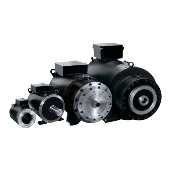
- Page 1 Operating instructions including the safety instructions TAM 00695 DST2-135 – 400 W Three-phase synchronous motor Water-cooled Version: 10 / 2019 TAM 00695 English DST2-135 – 400 W 10 / 2019 Three-phase synchronous motor, water-cooled English...
- Page 2 LEGAL NOTES ON DOCUMENTATION Copyright This documentation is only permitted to be copied by the owner for internal use. As many copies as required may be made. For other purposes, this documentation may not be copied or duplicated either in whole or in part. Utilisation and provision of the contents to third parties is not allowed.
-
Page 3: Table Of Contents
Table of contents General Safety Instructions ..................4 Safety ............................4 Designated use ......................... 5 Prohibition of unauthorised modifications and changes ............6 Operating conditions ....................6 Product description ........................6 Items supplied ........................... 7 Nameplate ..........................7 Technical Data .......................... 8 Transport, intermediate storage .................... -
Page 4: General Safety Instructions
General Safety Instructions Safety This electric motor has been constructed in accordance with the relevant safety standards and underwent an operational safety check before leaving our factory. To ensure correct commissioning and safe utilisation, please read the following: • these Commissioning and Maintenance Instructions and if applicable the enclosed supplementary parts •... -
Page 5: Designated Use
Designated use The electric motor must only be used for its designated purpose. In this context, the electric motor must only be used for the applications described in this technical documentation under strict observance of all the notes in these Commissioning and Maintenance Instructions. All assembly, commissioning, maintenance and operating tasks must be carried out by qualified personnel only. -
Page 6: Prohibition Of Unauthorised Modifications And Changes
Motor design with rare-earth magnets: Please be aware of the following risks in the vicinity of a retracted or exposed rotor with a strong magnetic field: People with electronic or metallic implants (e. g. cardiac pacemakers, hearing aids, plates or pins) are at risk, if the distance between the implant and the magnetic pole is less than 0.5 m. -
Page 7: Items Supplied
Items supplied The delivery is put together on an order-related basis. • The carrier must immediately be notified of any damage caused during transport. • On delivery, please check that the ratings and motor type correspond with the order data. In the event of apparent defects or incomplete delivery, the appropriate Baumüller office or the Baumüller head office in Nuremberg should be notified immediately. -
Page 8: Technical Data
Technical Data The technical data you can find in the technical product list DST2-135 - 400 W- or online at: www.baumueller.com under Download and Technical documentation. If necessary, you can request the corresponding documentation Storage Class 1K2/1M1 according to DIN EN 60721-3-1:1995 Transport Class 2K2/2M1 according to DIN EN 60721-3-2:1995 Note:... -
Page 9: Installation Conditions, Cooling Details
“DST2-..DG..” with thrust bearings have the following weights in the overall length classes: DST2-135 DST2-200 DST2-260 DST2-315 DST2-400 KO to YO KO to XY KO to XO KO to ZA KO to XY approx.130 kg to approx. 280 kg to approx. -
Page 10: Balancing, Drive Elements And Vibration
Balancing, drive elements and vibration The shaft and bearing must not be exposed to knocks. No axial forces are permitted when mounting or dismounting the output elements. The generally required measures to prevent contact with the output elements must be observed. -
Page 11: Mounting
Vibration: The site vibration response of the system, which is determined by the output elements, the mounting conditions, the alignment, the installation and the effects of external vibrations, may cause the vibration values at the motor to increase. In the interest of reliable motor operation and a long bearing service life, the permitted vibration values in accordance with EN 60034-14 should not be exceeded. -
Page 12: Vibrations And Resistance To Vibrations
When using standard solvents such as Acetone or benzine, the shaft sealing ring must not be moistened! • the motor is designed for the ambient conditions and environmental influences on site (see Section 2.4). • the compartment in the machine is suitable for the cooling method employed by the electric motor (see Section 2.6). - Page 13 The specified maximum radial and axial vibration values must be adhered to at the same time. They apply to substructures which can be described as elastic. An elastic substructure is present if the lowest natural frequency of the overall system (machine and base) in the measuring direction is at least 25% below the essential excitation frequency.
-
Page 14: Electrical Connections
Electrical connections Important notes: All work must be carried out by specially trained personnel. Work must only be carried out when the system has been de-energized and secured against unintentional restarting (also auxiliary circuits). Work may only be carried out once the machine has come to a standstill. In the case of three-phase synchronous motors with permanent-magnet excitation, a voltage of >... -
Page 15: Commissioning, Operation
In case of connection using a terminal box it is to be ensured • the insulation is not over stripped, i. e. that the insulation extends right up to the cable lugs or terminals. The ends of the cables must not protrude. •... -
Page 16: Checks Prior To Commissioning
Checks prior to commissioning • The drive is undamaged and is not located within the danger zone of other equipment • The motor is correctly aligned and fixed. All screwed connections are correctly tightened. Unused connection threads in the end shield have to be closed. •... -
Page 17: Malfunctions
Malfunctions Safety instructions: Troubleshooting and error recovery may only be carried out by qualified personnel. Do not disconnect any of the safety devices – even during test operations Only disconnect coolant pipes when depressurized Only disconnect and connect electrical connection cables when in de-energized and protected condition Observe the 5 safety rules for “Disconnecting”... -
Page 18: Inspection And Maintenance
Fault Cause Recovery Temperature rise in motor Drive overloaded Check motor load and Motor temperature monitoring compare with nameplate unit responds Brake does not release fully - Repair by motor manufacturer scraping brake Water cooling not active. Check and, if necessary, switch on Check water circuit Coolant supply inadequate... -
Page 19: Maintenance
If equipped with the optional shaft sealing ring, this must be checked regularly to ensure that it is functioning correctly (leaks). Note on thrust-bearing motors: An inspection hole for leak oil from the thrust-bearing housing is located on the bottom of the A-side bearing end plate near the feet (see Appendix 3 – Fig. 1). If oil exits here, the shaft sealing rings of both sealing points must be replaced. -
Page 20: Re-Lubrication (Optional)
5.3 Re-lubrication (optional) Attention: Re-lubrication only with grease outlet open. Prior to re-lubrication it is imperative that the covers be removed from the grease outlet opening. Re-grease bearing with re-lubrication device only when the motor is running. After re-lubrication, 2 - 4 hours of motor operation is necessary (the old bearing grease is ejected from the grease outlet opening by the rotation of the bearing), the cover is then to be refitted to the grease outlet opening. -
Page 21: Appendix 1: Pole Assignment (Main Connection And Control Port)
Appendix 1: pole assignment (main connection and control port) 7.1 Main connection with terminal box U V W Power connection 1R1/ 1R2 Temperature sensor (PT1000) 1R1/ 1R2 Temperature sensor Reserve Protection U V W Power connection K + K - Temperature sensor (KTY 84) (Reserve gebrückt) - Page 22 The following tightening torques M for the nuts on terminal boards, Wago-clamps etc. must be kept: thread M3,5 tightening torque M 10,0 15,5 30,0 52,0 in Nm Table 5: Tightening torque for screw nut TAM 00695 DST2-135 – 400 W 10 / 2019 Three-phase synchronous motor, water-cooled English...
-
Page 23: Control Port : Resolver
7.2 Control port : Resolver: Signal cos - sin – sin + View to contact side of female connector cos + Ref + Ref - Figure 3: Pool assignment resolver 7.3 Control port : SRS / SRM 50 (encoder with Hiperface-port from SICK / Stegmann companies) Signal ref cos + 485... -
Page 24: Control Port: Ecn 1313 / Eqn 1325
7.4 Control port: ECN 1313 / EQN 1325 (encoder with EnDat 2.1-port from Heidenhain companies Signal View to contact side of female connector Clock Clock inv. Data Data inv. Figure 5: Pool assignment ECN 1313 / EQN 1325 Note: For other encoder types and optional lead for the temperature sensor via the encoder cable, see the enclosed wiring diagram or technical documentation for the pin assignment ... -
Page 25: Appendix 2: Water-Cooled Machines
Appendix 2: water-cooled machines In addition to the previous chapters for water-cooled motors (EN 60034-6; IC 3W7) the following must be considered complementary: 8.1 Definitions of power ratings for water-cooled machines The power ratings (torques) that appear in the list apply to permanent operation S1 at nominal speed, provided the cooling circuit requirements for water-cooled motors are met! The reduction factors included in the table below must be considered when operating DST2 motors with higher coolant inlet temperatures:... -
Page 26: Electrical Connections
Leak test acc. to EN 50178: The cooling system is to be checked for leaks before commissioning by pressure testing with coolant (water). The test pressure must be twice the operating pressure (minimum test pressure 1 bar). The coolant used does not have to be brought to operating temperature for this purpose. -
Page 27: Min. Coolant Temperature Against Ambient Temperature And Humidity
8.7 Min. coolant temperature against ambient temperature and humidity ambient temperature (°C) Figure 6: Determination of the coolant temperature The allowed coolant temperature depends on relative humidity and ambient temperature. For example with an ambient temperature of 25 °C and a relative humidity of 65 % the minimum coolant temperature is 18 °C. -
Page 28: Inspection
Start Definition of min. ≥ T Definition rel. coolant temperature water ambience humidity (Section 1.3.2) > T water min.water (Section 1.3.2) ≤ 25 °C water Derating referred to ≤ 25 °C section 1.2.2 water 2-point controller = 70 °C restrictions = 50 °C restrictions ≤... -
Page 29: Appendix 3: Information Concerning Thrust-Bearing Motors And Oil-Features
Appendix 3: information concerning thrust-bearing motors and oil-features 9.1 Information on permissible axial forces on thrust-bearing motors Direction of force: from the connection side (DE) to the encoder side (NDE) Please refer to the Technical Product list DST2-135 - 400W for the axial forces possible in relation to the speed. - Page 30 Warranty and liability All the details in this documentation are unbinding customer information and subject to ongoing change and will be continuously updated by our permanent editing staff. Warranty and liability claims against Baumüller Nürnberg GmbH are excluded if, in particular, the damage is caused by one or more of the following: You have not followed the instructions in this documentation.
Need help?
Do you have a question about the DST2 Series and is the answer not in the manual?
Questions and answers