Table of Contents
Advertisement
Quick Links
©
KROHNE
7.02226.31.00
Status: 06-1999
Installation and operating
instructions
Level-Radar
BM 700
Variable area flowmeters
Vortex flowmeters
Flow controllers
Electromagnetic flowmeters
Ultrasonic flowmeters
Mass flowmeters
Level measuring instruments
Communications technology
Engineering systems & solutions
Advertisement
Table of Contents

Subscribe to Our Youtube Channel
Related Manuals for KROHNE BM 700


Summary of Contents for KROHNE BM 700
- Page 1 © KROHNE 7.02226.31.00 Installation and operating instructions Level-Radar BM 700 Variable area flowmeters Vortex flowmeters Flow controllers Electromagnetic flowmeters Ultrasonic flowmeters Mass flowmeters Level measuring instruments Communications technology Engineering systems & solutions Status: 06-1999...
- Page 2 3.00 + Suppl. instruction First serial version for BM 700. Items included with supply The scope of supply includes, in the version as ordered: • Signal converter bolted to waveguide window and antenna; optionally: antenna extension, sunshade (with fastening material in each case) •...
-
Page 3: Table Of Contents
The BM 700 level gauge is designed solely for measuring the level, distance, volume and reflection of liquids, pastes, slurries, particulate materials and solids. The BM 700 level gauge does not form part of an overfill protection system as defined in the WHG (= German water pollution regulation). -
Page 4: Installation
2 Installation Most of the BM 700 versions are supplied in fully assembled condition. In this case, you may skip this chapter. However, if a device should be delivered in parts, or parts are subsequently replaced, the following should be noted. -
Page 5: Mechanical Installation
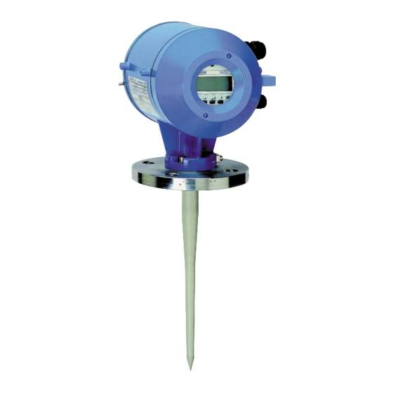
2.2 Mechanical installation Hazardous-duty systems: • The BM 700 Ex is certified in conformity with European Standard for use in Zone 0, 1 and 2 hazardous locations (dependent on version). • Attention is drawn to the data and information given on the nameplate of the converter, the nameplate of the flange and the specifications in the approval certificates. - Page 6 Installation on the tank • Do forget gasket when positioning the BM 700 on the tank nozzle flange. Align BM 700 and gasket, slightly tighten nuts on stud bolts (by hand). • Press shielding strip C* in the gap between tank and BM 700 flanges and secure with strap retainer S* (both items included with supply).
-
Page 7: Electrical Connection
Dimensions (W×H×D): 55×75×110 mm, usable for rail mounting Class of protection The BM 700 level gauge is designed for safety class 1 in conformity with VDE 0106 Part 1. 24 V DCAC supply When connected to a “functional extra-low voltage with safety separation“ power source (SELV or PELV) in accordance with VDE 0100, Part 410 or equivalent (inter)national regulations, connection of a safety conductor (PE) is not required. -
Page 8: Setting The Parameters
PC. Connect the current output of BM 700 over a load between 120 Ω and 350 Ω to the Smart adapter (delivered together with PC-CAT) and connect it with a serial port of the PC. - Page 9 The table on the following 2 pages provides an overview of all parameters that can be set in the configuration menu. This is followed by more precise explanations of some functions and a typical configuration. BM 700 Installation and Operating Instructions Page 9...
- Page 10 BARGRAPH/USER UNIT (see explanatory notes) 3.2.4 USER UNIT Text entry Enter user-defined unit for the 10 characters conversion table. 3.2.5 ERROR MSG. Select NO/YES Select whether error messages to be shown in display. Page 10 BM 700 Installation and Operating Instructions...
- Page 11 Select STORAGE T./ Select tank type. PROC TANK STORAGE T. = smooth product surface PROC TANK = slightly disturbed pro- duct surface Default values are shown in bold type in the table. BM 700 Installation and Operating Instructions Page 11...
- Page 12 The bottom reference point is that “point“ in the tank on which the microwaves of the BM 700 hit and from which they are reflected. This may be the tank bottom (symmetrical tank with flat bottom) or the non-horizontal part of the bottom (e.g.
- Page 13 • OFF: the empty-tank spectrum is not taken into account for measurements, but remains stored in the BM 700 and can be switched on again at a later date. • RECORD: the existing empty-tank spectrum is to be deleted and a new one recorded.
- Page 14 Fct. 3.5.1. Conversion table/Volume table A table consisting of a maximum of 50 points can be stored in the BM 700 for non- linear or linear conversion of the level, e.g. into a volumetric value. This table, however, can only be programmed with the PC-CAT program (Fct.
- Page 15 → Display of default value PROC tank ↑ ↑ Select tank type "storage tank" Storage t. ↵ Return to measurement function with Param.Check, confirmation of changed parameters then START, then meas.val. display BM 700 Installation and Operating Instructions Page 15...
-
Page 16: Maintenance, Error Handling
- or that there is no explosion hazard (gas-free certificate!). Replacement of the signal converter Before commencing, note the parameters of the BM 700 and switch off the power supply! 1. Detach safety lock at terminal compartment using Allen key (size 4 mm) and unscrew cover from terminal compartment using the special wrench. -
Page 17: Safety Information
• overvoltage category for the output circuit: II • insulation contamination level: 2 (inside the device) Disconnecting device The type BM 700 level gauge does not feature any device for switching or dis- connection. Hazardous-duty systems • Types of protection in the BM 700 terminal compartment: Increased Safety “e“... -
Page 18: Technical Data (Extract)
High temp. version, FFKM: max. +250°C (482°F) Kalrez 2035: max. +210°C (410°F) FPM (Viton) or FEP-coated: max. +200°C (392°F) PTFE-Wave-Stick: -20°C (-4°F) to + 150°C (302°F), pressure depend PP-Wave-Stick: -20°C (-4°F) to + 100°C (212°F) Page 18 BM 700 Installation and Operating Instructions... -
Page 19: Bm 700 Level-Radar Type Code
Cable cross-section 0.5-2.5 mm² (AWG 20-14) (solid conductor: max. 4 mm² (AWG 12)) U-clamp terminals (for PA and FE) cable cross-section max. 4 mm² (AWG 12) 8 BM 700 Level-Radar Type code Series V96 or LP: Series WS: Terminal cover... - Page 20 (versions V96, or Wave-Stick LPTFE or PTFE with Metaglass) equipment category 2, application in Zone 1 (Wave-Stick PP or PTFE without Metaglass, or LP flange system) (free) Without Ex approval (e.g. LP version) Page 20 BM 700 Installation and Operating Instructions...
-
Page 21: Parameter Check List Bm 700
––– +130°C (+266°F) +150°C (+302°F) WS SS PP - 20°C (- 4°F) ––– +100°C (+212°F) +100°C (+212°F) 9 Parameter check list BM 700 Menu item changed on Version: Fct. Configuration parameters (extract) 3.1.1 Tank height 3.1.2 Block distance 3.1.3 Antenna 3.1.4 Antenna extension... -
Page 22: Appendix
The installation and operation of the radio transmitting and receiving system "BM 70 Level Radar" and "BM 70 Ex Level Radar" manufactured by Firma KROHNE Messtechnik GmbH & quency in the 8.1 9.4 GHz frequency range, is hereby authorized pursuant to §§ 1 and 2 of the law concerning telecommunication systems as adopted in the dated 03.07.1989. - Page 23 The above-mentioned general licence for radio installations issued to the company of KROHNE Messtechnik GmbH & Co. KG, 47058 Duisburg, shall with immediate effect also include radio installations that operate at a frequency in the frequency range of 8.1 - 9.9 GHz, for the same purpose are placed by the company on the market and which are marked in accordance with the general licence.
- Page 24 Allgemeingenehmigung Nr. 353 für Sende- und Empfangsfunkanlagen Das Errichten und Betreiben der Sende- und Empfangsfunkanlage "BM 70 Level Radar" sowie "BM 70-Ex Level Radar" der Firma KROHNE Meßtechnik GmbH & Co. KG, 4100 Duisburg, für Fernwirkzwecke (Füllstandsmessungen in Metalltanks) auf einer Frequenz im Frequenzbereich 8,1 - 9,4 GHz, wird aufgrund der §§...
- Page 25 Erweiterung der Allgemeingenehmigung Nr. 353 für Sende- und Empfangsfunkanlagen Zur AmtsblVfg 1117/1989, S.2066 Die obengenannte Allgemeingenehmigung für Funkanlagen der Firma KROHNE Meßtechnik GmbH & Co. KG, 47058 Duisburg, erstreckt sich ab sofort auch auf die Funkanlagen, die auf einer Frequenz im Frequenzbereich 8,1 - 9,9 GHz arbeiten, von der Firma für den gleichen Verwendungszweck in den Verkehr gebracht werden und die entsprechend der Allgemeingenehmigung gekennzeichnet sind.
Need help?
Do you have a question about the BM 700 and is the answer not in the manual?
Questions and answers