Table of Contents
Advertisement
Quick Links
BM 26 BASIC/ADVANCED
BM 26 BASIC/ADVANCED
BM 26 BASIC/ADVANCED
BM 26 BASIC/ADVANCED
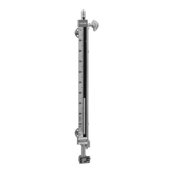
Magnetic Bypass Level Indicators (MLI) for general-
purpose applications
Supplementary Instructions for ATEX applications
Supplementary Instructions for ATEX applications
Supplementary Instructions for ATEX applications
Supplementary Instructions for ATEX applications
© KROHNE 06/2016 - 4000347104 - AD ATEX BM 26 Bas-Adv R04 en
Supplementary Instructions
Supplementary Instructions
Supplementary Instructions
Supplementary Instructions
Advertisement
Table of Contents

Subscribe to Our Youtube Channel
Related Manuals for KROHNE BM 26 BASIC


Summary of Contents for KROHNE BM 26 BASIC
- Page 1 Magnetic Bypass Level Indicators (MLI) for general- purpose applications Supplementary Instructions for ATEX applications Supplementary Instructions for ATEX applications Supplementary Instructions for ATEX applications Supplementary Instructions for ATEX applications © KROHNE 06/2016 - 4000347104 - AD ATEX BM 26 Bas-Adv R04 en...
- Page 2 CONTENTS BM 26 BASIC/ADVANCED 1 Introduction 2 Measuring chamber 2.1 General safety information....................5 2.1.1 Scope ............................5 2.1.2 Device description........................5 2.1.3 Standards and approvals ......................5 2.1.4 Categories: c-approved devices ..................... 6 2.1.5 ATEX nameplates: measuring chamber................. 7 2.2 Installation........................
-
Page 3: Table Of Contents
CONTENTS BM 26 BASIC/ADVANCED 5 Assembled equipment 5.1 General safety information..................... 25 5.1.1 Scope ............................. 25 5.1.2 Standards and approvals ...................... 26 5.1.3 Categories ..........................26 5.2 Installation........................27 5.2.1 Precautions ........................... 27 5.2.2 Operating conditions ......................28 5.3 Electrical connections ....................33 5.4 Start-up........................... - Page 4 • MS40 limit switch INFORMATION! If you use the LT40 analog transmitter without the BM 26 Basic or BM 26 Advanced measuring chamber, refer to Analog transmitter on page 17 If you use the MS40 limit switch without the BM 26 Basic or BM 26 Advanced measuring...
-
Page 5: General Safety Information
MEASURING CHAMBER BM 26 BASIC/ADVANCED 2.1 General safety information 2.1.1 Scope These instructions are applicable only to the explosion-protection version of the measuring chamber. For all other data, use the Quick Start and Handbook for the magnetic level indicator. If you do not have these documents, please contact the nearest sales office or download them from the website www.krohne.com. -
Page 6: Categories
MEASURING CHAMBER BM 26 BASIC/ADVANCED 2.1.4 Categories: c-approved devices The c-approved device has the markings that follow: BM 26 Basic Without adhesive label and without PLEXIGLAS® anti-freeze protection: II 1 G c IIC T6...T3 With adhesive label, but without PLEXIGLAS® anti-freeze protection: II 1/2 G c IIC T6...T3... -
Page 7: Installation
MEASURING CHAMBER BM 26 BASIC/ADVANCED 2.1.5 ATEX nameplates: measuring chamber Figure 2-1: ATEX nameplate for the Basic and Advanced version of the bypass level indicator (measuring chamber) 1 ATEX certification code. Refer also to temperature classes temperature classes. temperature classes... - Page 8 MEASURING CHAMBER BM 26 BASIC/ADVANCED Special conditions WARNING! The anti-freeze cover option is possible source of ignition in a potentially explosive atmosphere. It covers the glass tube of the indicator column. Clean the anti-freeze cover option only with a damp cloth.
- Page 9 MEASURING CHAMBER BM 26 BASIC/ADVANCED Advanced version (without electrical equipment) The ATEX equipment category and temperature class give the ambient temperature and related process temperature ranges for the device. -70°C / -94°F is the minimum temperature for the Advanced version of the magnetic level indicator.
- Page 10 MEASURING CHAMBER BM 26 BASIC/ADVANCED 2.3 Electrical connections 2.3.1 Potential earth (PE): measuring chamber Connect an electrical cable with a metallic shield to the PE. The PE is installed at the bottom of the measuring chamber, on the side of the device nameplate.
- Page 11 LIMIT SWITCH BM 26 BASIC/ADVANCED 3.1 General safety information 3.1.1 Scope These instructions are applicable only to the explosion-protection version of the bistable limit switch. For all other data, use the Quick Start and Handbook for the magnetic level indicator. If you do not have these documents, please contact the nearest sales office or download them from the website www.krohne.com.
-
Page 12: Operating Conditions
LIMIT SWITCH BM 26 BASIC/ADVANCED 3.1.4 Categories: Ex ia-approved devices The Ex ia-approved device has the markings that follow: II 1 GD Ex ia IIC T4…T6* Ga Ex ia IIIC T135°C…T85°C* Da * The ambient temperature for the device must agree with the temperature class data on page The limit switch is designed for ATEX applications when the appropriate options are selected (type code *F40**1**). - Page 13 LIMIT SWITCH BM 26 BASIC/ADVANCED 3.1.5 ATEX nameplates: level switch Figure 3-1: Ex i nameplate for the level switch (non-Namur) Figure 3-2: Ex i nameplate for the level switch (Namur) 1 ATEX certification agency code. Refer also to temperature classes temperature classes.
- Page 14 LIMIT SWITCH BM 26 BASIC/ADVANCED 3.2 Installation 3.2.1 Precautions General notes WARNING! When you install the device, obey the conditions in the EC-Type Examination certificate. These conditions include: The special conditions for safe use. • The Essential Health and Safety Requirements.
-
Page 15: Electrical Connections
LIMIT SWITCH BM 26 BASIC/ADVANCED 3.2.2 Operating conditions The ATEX equipment category and temperature class give the ambient temperature range for the limit switch. This data is marked on the nameplate of the limit switch. Equipment category II 1 G or 1 D (Ex i applications and non-Namur devices only) -
Page 16: Start-Up
LIMIT SWITCH BM 26 BASIC/ADVANCED Non-NAMUR limit switches: Maximum intrinsically-safe values for the electrical circuit ≤250 VAC/DC • U ≤1 A • I ≤60 VA/W • P ≈0 nF • C =0 μH • L NAMUR limit switches: Maximum intrinsically-safe values for the electrical circuit ≤24 V... - Page 17 For all other data, use the Quick Start and Handbook for the magnetic level indicator. If you do not have these documents, please contact the nearest sales office or download them from the website www.krohne.com. WARNING! Installation, commissioning and maintenance may only be carried out by "Personnel trained in explosion protection".
- Page 18 ANALOG TRANSMITTER BM 26 BASIC/ADVANCED 4.1.3 Standards and approvals DANGER! In compliance with European Directives 94/9/EC (applicable until 19 April 2016) and 2014/34/EU (applicable from 20 April 2016), the ATEX versions of the analog transmitter described in these Supplementary Instructions conform to European Standards EN 60079-0:2012 + A11 :2013, EN 60079-11 :2012, EN 60079-26 :2015.
- Page 19 ANALOG TRANSMITTER BM 26 BASIC/ADVANCED Category 1 D equipment are used in zone 20. Category 2 D equipment are used in zone 21. 4.1.5 ATEX nameplates: analog transmitter Figure 4-1: Ex i nameplates for the analog transmitter with a 4...20 mA transmitter module or a 4...20 mA+HART®...
- Page 20 ANALOG TRANSMITTER BM 26 BASIC/ADVANCED 4.2 Installation 4.2.1 Precautions General notes WARNING! When you install the device, obey the conditions in the EC-Type Examination certificate. These conditions include: The special conditions for safe use. • The Essential Health and Safety Requirements.
- Page 21 ANALOG TRANSMITTER BM 26 BASIC/ADVANCED 4.2.2 Operating conditions The ATEX equipment category and temperature class give the maxiumum ambient temperature for the analog transmitter. This data is marked on the nameplate of the analog transmitter. Because the product temperature has an effect on the device, more than one temperature class is given.
- Page 22 ANALOG TRANSMITTER BM 26 BASIC/ADVANCED Minimum ambient temperature for the analog transmitter Module output Module designation Minimum ambient temperature [°C] [°F] 4...20 mA xF45xB1xx 4...20 mA + HART® (PR) xF45xW1xx 4...20 mA + indicator xF45xE1xx 4...20 mA + HART® + indicator...
- Page 23 ANALOG TRANSMITTER BM 26 BASIC/ADVANCED Module output Converter Marking Electrical circuit characteristics designation [mA] [nF] [µH] 4...20 mA + indicator xF45xE1xx II 1 GD 0.84 32.1 Ex ia IIC T4…T5 Ga 4...20 mA + indicator xF45xE1xx 0.84 Ex ia IIIC T135°C…T100°C Da 4...20 mA + HART®...
-
Page 24: Periodic Maintenance
ANALOG TRANSMITTER BM 26 BASIC/ADVANCED 4.5 Periodic maintenance In normal operational conditions, no maintenance is necessary. If it is necessary, maintenance must be done by approved personnel (the manufacturer or personnel approved by the manufacturer). CAUTION! We recommend that you do regular inspections. Do a check of the housing cable entries and electrical wires for damage and corrosion. - Page 25 ASSEMBLED EQUIPMENT BM 26 BASIC/ADVANCED 5.1 General safety information 5.1.1 Scope These instructions are applicable only to the explosion-protection version of the measuring chamber with 1 of these 3 options that follow: • the explosion-protection version of the analog transmitter or •...
- Page 26 ASSEMBLED EQUIPMENT BM 26 BASIC/ADVANCED 5.1.2 Standards and approvals DANGER! The ATEX versions of the assembled equipment agree with European Directives 94/9/EC (applicable until 19 April 2016) and 2014/34/EU (applicable from 20 April 2016). • For the applicable European Standards and approvals for the measuring chamber, refer to Standards and approvals on page 5.
- Page 27 ASSEMBLED EQUIPMENT BM 26 BASIC/ADVANCED 5.2 Installation 5.2.1 Precautions General notes WARNING! When you install the device, obey the conditions in the EC-Type Examination certificates for the applicable equipment. These conditions include: The special conditions for safe use. • The Essential Health and Safety Requirements.
- Page 28 ASSEMBLED EQUIPMENT BM 26 BASIC/ADVANCED WARNING! Insulation of the analog transmitter Insulation of the analog transmitter Insulation of the analog transmitter Insulation of the analog transmitter The Ex data for this device is only applicable if you obey these instructions: Put insulation between the measuring chamber and the analog transmitter.
- Page 29 ASSEMBLED EQUIPMENT BM 26 BASIC/ADVANCED Maximum process temperature Temperature class Maximum process temperature Dust [°C] [°F] T85°C +154 T100°C +176 T135°C +108 +226 T200°C +160 +320 T300°C +240 +464 T450°C +360 +680 Maximum ambient temperature: measuring chamber with limit switches...
- Page 30 ASSEMBLED EQUIPMENT BM 26 BASIC/ADVANCED Temperature class Ambient temperature range (Gas / Dust) 4...20 mA 4...20 mA + HART 4...20 mA + 4...20 mA + HART + (PR) indicator indicator xF45xB1xx xF45xW1xx xF45xE1xx xF45xG1xx T3 / T200°C [°C] -40...+80 -40...+80 -20...+48...
- Page 31 ASSEMBLED EQUIPMENT BM 26 BASIC/ADVANCED Ambient temperature range: measuring chamber with an analog transmitter (FF and PROFIBUS PA outputs) – Part 2 – Alternatives for xF45xD1xx and xF45xX1xx Equipment group Outputs Refer to alternative number and category II 1 GD...
- Page 32 ASSEMBLED EQUIPMENT BM 26 BASIC/ADVANCED Temperature class Ambient temperature range (Gas / Dust) FOUNDATION™ fieldbus (xF45xD1xx) / PROFIBUS PA (xF45xX1xx) PROFIBUS PA (xF45xA1xx) Conventional FISCO intrinsically-safe systems intrinsically-safe systems Alternative T1 / T450°C [°C] -40...+77 -40...+67 -40...+77 -40...+77 -40...+77 -40...+77 -40...+77...
- Page 33 ASSEMBLED EQUIPMENT BM 26 BASIC/ADVANCED 5.3 Electrical connections DANGER! The ambient temperature will have an affect on the electrical characteristics of intrinsically safe systems. For more data about maximum ambient temperature, refer to Operating conditions on page 28 For more electrical data about pieces of equipment, refer to the "Electrical connections"...
-
Page 34: Keep The Device Clean
SERVICE BM 26 BASIC/ADVANCED 6.1 Periodic maintenance No maintenance is necessary. INFORMATION! For more data about regular inspections and maintenance procedures for devices with Ex and other approvals, refer to the related supplementary instructions. 6.2 Keep the device clean DANGER! If you rub the anti-freeze cover option with a dry cloth, there is a risk of electrostatic discharge. -
Page 35: Form (For Copying) To Accompany A Returned Device
SERVICE BM 26 BASIC/ADVANCED 6.3.2 Form (for copying) to accompany a returned device CAUTION! To avoid any risk for our service personnel, this form has to be accessible from outside of the packaging with the returned device. Company: Address: Department: Name: Tel. - Page 36 • Process Analysis • Services Head Office KROHNE Messtechnik GmbH Ludwig-Krohne-Str. 5 47058 Duisburg (Germany) Tel.: +49 203 301 0 Fax: +49 203 301 10389 info@krohne.com The current list of all KROHNE contacts and addresses can be found at: www.krohne.com...
Need help?
Do you have a question about the BM 26 BASIC and is the answer not in the manual?
Questions and answers