Table of Contents
Advertisement
Quick Links
BM 26 BASIC/ADVANCED
BM 26 BASIC/ADVANCED
BM 26 BASIC/ADVANCED
BM 26 BASIC/ADVANCED
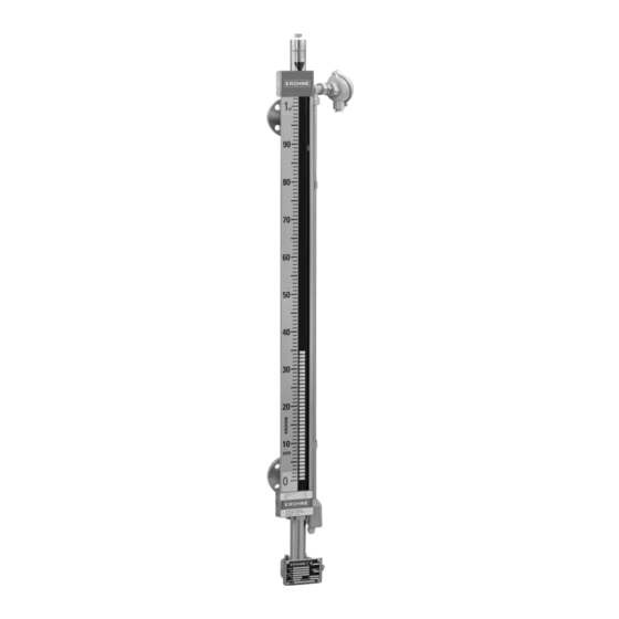
Stainless Steel Bypass Level Indicators for applications
up to 40 barg / 580 psig
Supplementary Instructions for ATEX applications
Supplementary Instructions for ATEX applications
Supplementary Instructions for ATEX applications
Supplementary Instructions for ATEX applications
© KROHNE 12/2011 - 4000347102 - AD ATEX BM 26 Bas-Adv R02 en
Supplementary instructions
Supplementary instructions
Supplementary instructions
Supplementary instructions
Advertisement
Table of Contents

Related Manuals for KROHNE BM 26 BASIC


Summary of Contents for KROHNE BM 26 BASIC
- Page 1 40 barg / 580 psig Supplementary Instructions for ATEX applications Supplementary Instructions for ATEX applications Supplementary Instructions for ATEX applications Supplementary Instructions for ATEX applications © KROHNE 12/2011 - 4000347102 - AD ATEX BM 26 Bas-Adv R02 en...
-
Page 2: Table Of Contents
CONTENTS BM 26 BASIC/ADVANCED 1 Measuring chamber 1.1 General safety information....................4 1.1.1 Scope ............................4 1.1.2 Device description........................4 1.1.3 Standards and approvals ......................4 1.1.4 Categories ..........................5 1.1.5 ATEX nameplates: measuring chamber................. 6 1.2 Installation........................6 1.2.1 Precautions ..........................6 1.2.2 Operating conditions ....................... - Page 3 CONTENTS BM 26 BASIC/ADVANCED 4.2 Installation........................22 4.2.1 Precautions ........................... 22 4.2.2 Operating conditions ......................23 4.3 Electrical connections ....................26 4.4 Start-up........................... 26 5 Service 5.1 Periodic maintenance..................... 27 5.2 Keep the device clean..................... 27 5.3 Returning the device to the manufacturer..............27 5.3.1 General information......................
-
Page 4: Measuring Chamber
MEASURING CHAMBER BM 26 BASIC/ADVANCED 1.1 General safety information 1.1.1 Scope These instructions are applicable only to the explosion-protection version of the measuring chamber. For all other data, use the Quick Start and Handbook for the magnetic level indicator. If you do not have these documents, please contact the nearest sales office or download them from the website www.krohne.com. -
Page 5: Categories
MEASURING CHAMBER BM 26 BASIC/ADVANCED 1.1.4 Categories The Basic and Advanced versions of the magnetic level Indicator are designed for ATEX applications when the appropriate option is selected (type code *F41**1**********************). Category 1 Category 1 Category 1 Category 1 The measuring chamber is installed in hazardous areas requiring Category 1 G equipment. -
Page 6: Atex Nameplates: Measuring Chamber
MEASURING CHAMBER BM 26 BASIC/ADVANCED 1.1.5 ATEX nameplates: measuring chamber Figure 1-1: ATEX nameplate for Basic version of the bypass level indicator Figure 1-2: ATEX nameplate for Advanced version of the bypass level indicator 1 ATEX certification agency code. Refer also to temperature classes temperature classes. -
Page 7: Operating Conditions
MEASURING CHAMBER BM 26 BASIC/ADVANCED Electrostatic discharge DANGER! Risk of electrostatic discharge from the anti-freeze cover option. Make sure that all personnel and equipment are correctly grounded. Take the necessary antistatic precautions if you: • handle, • install or • use the device in potentially explosive atmospheres. - Page 8 MEASURING CHAMBER BM 26 BASIC/ADVANCED Equipment category II 2 G and 3 G Temperature class Maximum ambient Maximum process temperature temperature [°C] [°F] [°C] [°F] +176 +176 +176 +203 +176 +130 +266 +176 +150 +302 Advanced version (without electrical equipment) The ATEX equipment category and temperature class give the ambient temperature and related process temperature ranges for the device.
-
Page 9: Electrical Connections
MEASURING CHAMBER BM 26 BASIC/ADVANCED 1.3 Electrical connections 1.3.1 Potential earth (PE): measuring chamber Connect an electrical cable with a metallic shield to the PE. The PE is installed at the bottom of the measuring chamber, on the side of the device nameplate. -
Page 10: Limit Switch
LIMIT SWITCH BM 26 BASIC/ADVANCED 2.1 General safety information 2.1.1 Scope These instructions are applicable only to the explosion-protection version of the bistable limit switch. For all other data, use the Quick Start and Handbook for the magnetic level indicator. If you do not have these documents, please contact the nearest sales office or download them from the website www.krohne.com. -
Page 11: Atex Nameplates: Level Switch
LIMIT SWITCH BM 26 BASIC/ADVANCED INFORMATION! The limit switch can also be installed in hazardous areas requiring Category 2 or Category 3 equipment. 2.1.5 ATEX nameplates: level switch xF40xx1x1 Manuf. date: DD/MM/YYYY S/N: xxxxxxxxxxxxxxxxxxx INERIS 08ATEX0045X II 1G Ex ia IIC T4...T6... -
Page 12: Installation
LIMIT SWITCH BM 26 BASIC/ADVANCED 2.2 Installation 2.2.1 Precautions General notes WARNING! When you install the device, obey the conditions in the EC-Type Examination certificate. These conditions include: The special conditions for safe use. • The Essential Health and Safety Requirements. -
Page 13: Electrical Connections
LIMIT SWITCH BM 26 BASIC/ADVANCED 2.3 Electrical connections 2.3.1 Ex i limit switches • Use the electrical connection procedure in the Handbook. • If possible, use galvanically-isolated equipment. • Supply the Ex i equipment connected to the limit switch. Use only certified intrinsically-safe equipment. -
Page 14: Analog Transmitter
For all other data, use the Quick Start and Handbook for the magnetic level indicator. If you do not have these documents, please contact the nearest sales office or download them from the website www.krohne.com. WARNING! Installation, commissioning and maintenance may only be carried out by "Personnel trained in explosion protection". -
Page 15: Standards And Approvals
ANALOG TRANSMITTER BM 26 BASIC/ADVANCED This accessory is approved for use in potentially explosive atmospheres when equipped with the appropriate options. 3.1.3 Standards and approvals DANGER! In compliance with European Directive 94 / 9 / EC (ATEX 100a), the ATEX versions of the analog transmitter described in these Supplementary Instructions conform to European Standards EN 60079-0:2006, EN 60079-11:2007, EN 60079-26:2007. -
Page 16: Atex Nameplates: Analog Transmitter
ANALOG TRANSMITTER BM 26 BASIC/ADVANCED 3.1.5 ATEX nameplates: analog transmitter KROHNE S.A.S. F-26103 Romans www.krohne.com LT40 0344 Figure 3-1: Ex i nameplates for the analog transmitter with a 4...20 mA module ® Figure 3-2: Ex i nameplates for the analog transmitter with a 4...20 mA+HART module 1 Analog transmitter with 4...20 mA module... -
Page 17: Installation
ANALOG TRANSMITTER BM 26 BASIC/ADVANCED Figure 3-3: Ex i nameplates for the analog transmitter with a fieldbus module 1 Analog transmitter with FOUNDATION™ Fieldbus module (PR) ® 2 Analog transmitter with PROFIBUS PA module (PR) ® 3 Analog transmitter with PROFIBUS PA module 4 ATEX certification agency code. -
Page 18: Operating Conditions
ANALOG TRANSMITTER BM 26 BASIC/ADVANCED 3.2.2 Operating conditions The ATEX equipment category and temperature class give the maxiumum ambient temperature for the analog transmitter. This data is marked on the nameplate of the analog transmitter. Maximum ambient temperature for the analog transmitter... -
Page 19: Electrical Connections
ANALOG TRANSMITTER BM 26 BASIC/ADVANCED 3.3 Electrical connections 3.3.1 Ex i analog transmitter • Use the electrical connection procedure in the Handbook. • If possible, use galvanically-isolated equipment. • Supply the Ex i equipment connected to the analog transmitter. Use only certified intrinsically- safe equipment. -
Page 20: Start-Up
ANALOG TRANSMITTER BM 26 BASIC/ADVANCED 3.4 Start-up Do a start-up check: • Does the information given on the nameplate agree with the application? • Ex i applications: Ex i applications: Ex i applications: Are you using an intrinsically-safe barrier within the correct parameters? -
Page 21: Assembled Equipment
ASSEMBLED EQUIPMENT BM 26 BASIC/ADVANCED 4.1 General safety information 4.1.1 Scope These instructions are applicable only to the explosion-protection version of the measuring chamber with 1 of these 3 options that follow: • the explosion-protection version of the analog transmitter or •... -
Page 22: Categories
ASSEMBLED EQUIPMENT BM 26 BASIC/ADVANCED 4.1.3 Categories Equipment categories for assembled equipment: Categories • For data on equipment categories for the measuring chamber, refer to on page 5. Categories • For data on equipment categories for the limit switch, refer to on page 10. -
Page 23: Operating Conditions
ASSEMBLED EQUIPMENT BM 26 BASIC/ADVANCED WARNING! Insulation of the analog transmitter Insulation of the analog transmitter Insulation of the analog transmitter Insulation of the analog transmitter The Ex data for this device is only applicable if you obey these instructions: Put insulation between the measuring chamber and the analog transmitter. - Page 24 ASSEMBLED EQUIPMENT BM 26 BASIC/ADVANCED Temperature class Maximum process temperature [°C] [°F] +240 +464 +300 +572 Maximum ambient temperature: measuring chamber with limit switches Temperature class Maximum ambient temperature Measuring chamber with non- Measuring chamber with NAMUR NAMUR limit switch limit switch [°C]...
- Page 25 ASSEMBLED EQUIPMENT BM 26 BASIC/ADVANCED Maximum ambient temperature: measuring chamber with an analog transmitter (FF and PROFIBUS PA outputs) - Part 2 Temperature class Maximum ambient temperature FOUNDATION™ Fieldbus (xF45xD1xx) / PROFIBUS PA (xF45xX1xx) PROFIBU - PR S PA (xF45xA1...
-
Page 26: Electrical Connections
ASSEMBLED EQUIPMENT BM 26 BASIC/ADVANCED 4.3 Electrical connections DANGER! The ambient temperature will have an affect on the electrical characteristics of intrinsically safe systems. For more data about maximum ambient temperature, refer to Operating conditions on page 23 For more electrical data about pieces of equipment, refer to the "Electrical connections"... -
Page 27: Service
SERVICE BM 26 BASIC/ADVANCED 5.1 Periodic maintenance No maintenance is necessary. 5.2 Keep the device clean DANGER! If you rub the anti-freeze cover option with a dry cloth, there is a risk of electrostatic discharge. Clean the anti-freeze cover option only with a damp cloth. -
Page 28: Form (For Copying) To Accompany A Returned Device
SERVICE BM 26 BASIC/ADVANCED 5.3.2 Form (for copying) to accompany a returned device Company: Address: Department: Name: Tel. no.: Fax no.: Manufacturer's order no. or serial no.: The device has been operated with the following medium: This medium is: water-hazardous... -
Page 29: Notes
NOTES BM 26 BASIC/ADVANCED 12/2011 - 4000347102 - AD ATEX BM 26 Bas-Adv R02 en www.krohne.com... - Page 30 NOTES BM 26 BASIC/ADVANCED www.krohne.com 12/2011 - 4000347102 - AD ATEX BM 26 Bas-Adv R02 en...
- Page 31 NOTES BM 26 BASIC/ADVANCED 12/2011 - 4000347102 - AD ATEX BM 26 Bas-Adv R02 en www.krohne.com...
- Page 32 Measuring systems for the oil and gas industry • Measuring systems for sea-going tankers Head Office KROHNE Messtechnik GmbH Ludwig-Krohne-Str. 5 D-47058 Duisburg (Germany) Tel.:+49 (0)203 301 0 Fax:+49 (0)203 301 10389 info@krohne.de The current list of all KROHNE contacts and addresses can be found at: www.krohne.com...
Need help?
Do you have a question about the BM 26 BASIC and is the answer not in the manual?
Questions and answers