Advertisement
Cautions and
Warnings
Introduction
2005, 2006, 2013 Tyco Fire Protection Products. All rights reserved.
Specifications and other information shown were current as of publication and are subject to change without notice.
TYCO, SIMPLEX, and the product names listed in this material are marks and/or registered marks. Unauthorized use is strictly prohibited.
DO NOT INSTALL ANY SIMPLEX
your Simplex product, inspect the contents of the carton for shipping damage. If damage is apparent,
immediately file a claim with the carrier and notify an
ELECTRICAL HAZARD - Disconnect electrical field power when making any internal adjustments or
repairs. All repairs should be performed by a representative or authorized agent of your local Simplex
product supplier.
STATIC HAZARD - Static electricity can damage components. Handle as follows:
Ground yourself before opening or installing components.
Prior to installation, keep components wrapped in anti-static material at all times.
FCC RULES AND REGULATIONS – PART 15 — This equipment has been tested and found to comply
with the limits for a Class A digital device, pursuant to Part 15 of the FCC Rules. These limits are designed to
provide reasonable protection against harmful interference when the equipment is operated in a commercial
environment. This equipment generates, uses, and can radiate radio frequency energy and, if not installed and
used in accordance with the instruction manual, may cause harmful interference to radio communications.
Operation of this equipment in a residential area is likely to cause harmful interference in which case the user
will be required to correct the interference at his own expense.
The TrueAlert family of notification appliances provides addressable control and supervision of
individual appliances and circuit wiring. Appliances are operated over a single two-wire notification
appliance circuit (TrueAlert Channel) that allows T-tapping (Class B only). The TrueAlert Isolator
+ Module provides a means of containing the effects of a short circuit on the TrueAlert Channel to a
single segment of wire, as well as an aid in locating stray connections to earth ground. The
TrueAlert Channel can be broken into segments called Virtual NACs (VNACs) in both Class B
and Class A circuit topologies using the TrueAlert Isolator + module to abut segments. TrueAlert
Isolator + Modules operate contact switches through commands received over the 2-wire
TrueAlert circuit from the 4009 TrueAlert Addressable Controller and TrueAlert Power Supply
(TPS). TrueAlert Isolator + modules automatically isolate the short to a single segment of wire,
but require a command from the host panel to restore the connection. Manual control of opening
and closing the contacts is also available through the TrueAlert Power Supply.
The range of possible temperatures under which the TrueAlert Isolator + can function is between
0C (32F) and 49C (120F).
The TrueAlert Isolator + operates normally under non-condensing humidity conditions up to 93%
with relative humidity at 38C (100F).
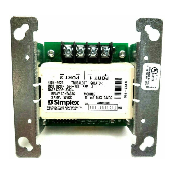
The TrueAlert Isolator + Module has a LED that the TrueAlert Addressable Controller can
command to Flash ON, OFF, or blink when polled. See Figure 1, TrueAlert Isolator + Module.
Note: The TrueAlert Isolator + Module is a faster version of the original TrueAlert Isolator. It is a
100% backwards compatible replacement for the original version. You will not necessarily gain
the enhanced speed benefit of the short isolation unless all your isolators are the new "+" type on
the same TrueAlert Channel. The "+" version can be identified by looking at the silkscreen on the
PCA for "TrueAlert Isolator +" located near the terminal block.
4905 TrueAlert Isolator +
Installation Instructions
®
PRODUCT THAT APPEARS DAMAGED. Upon unpacking
authorized
Product Supplier
Simplex
.
.
574-769
Rev. C
Advertisement
Table of Contents

Related Manuals for Simplex TrueAlert Isolator+


Summary of Contents for Simplex TrueAlert Isolator+
- Page 1 574-769 Specifications and other information shown were current as of publication and are subject to change without notice. Rev. C TYCO, SIMPLEX, and the product names listed in this material are marks and/or registered marks. Unauthorized use is strictly prohibited.
- Page 2 Installation instructions, Continued Installation instructions, Continued This publication discusses the following topics: In this Publication Topic See Page TrueAlert Isolator + Wiring TrueAlert Isolator + Class B Wiring TrueAlert Isolator + Class A Wiring Mounting the TrueAlert Isolator + Module Setting the TrueAlert Isolator + Module Address TrueAlert Isolator + Wiring...
- Page 3 Installation instructions, Continued TrueAlert Isolator + Class B Wiring4-769- EPS IDNAC, 4009 IDNAC Repeater, 4009 TrueAlert Addressable Controller or TrueAlert Non-Isolated Power Supply Devices 4905-9929 TrueAlert Isolator + Module Isolated Devices TERMINALS ACCEPT (non-powered 2 WIRES: #12 - #18 AWG when isolated) (SEE NOTE 5 in Figure 3) Note:...
- Page 4 Installation instructions, Continued TrueAlert Isolator + 4905-9929 TrueAlert Class A Wiring Isolator + Module 4905-9929 Isolator Module CKT + CKT + CKT - CKT - 4905-9929 TrueAlert 4905-9929 TrueAlert Isolator + Module Isolator + Module 4905-9929 Isolator Module 4905-9929 Isolator Module CKT - CKT + Port 2...
- Page 5 Installation instructions, Continued Mounting the The TrueAlert Isolator + module mounts to the 4-inch square grounded metal electrical box via 2 TrueAlert Isolator + screws. Box depth is dependent on the number and size of conductors used in a particular Module application.
- Page 6 Installation instructions, Continued The True Alert Isolator + has a unique address. Each device’s address is set via an eight-position Setting the TrueAlert DIP switch, as shown in Table 1. See Figure 1 for the general DIP switch location. DIP switch Isolator + Module Address position 1 is the least significant bit (LSB) and position 8 is the most significant bit (MSB).
Need help?
Do you have a question about the TrueAlert Isolator+ and is the answer not in the manual?
Questions and answers