Panasonic FP7 Series User Manual
Cpu unit
Hide thumbs
Also See for FP7 Series:
- Command reference manual (1222 pages) ,
- User manual (275 pages) ,
- Additional functions manual (45 pages)

Related Manuals for Panasonic FP7 Series


Summary of Contents for Panasonic FP7 Series
- Page 1 PROGRAMMABLE CONTROLLER FP7 CPU Unit User's Manual Hardware WUME-FP7CPUH-07 2019.11 panasonic.net/id/pidsx/global...
- Page 2 -This manual and its contents are copyrighted. -You may not copy this manual, in whole or part, without written consent of Panasonic Industrial Devices SUNX Co., Ltd. -Windows is a registered trademark of Microsoft Corporation in the United States and other countries.
- Page 3 Introduction Introduction Thank you for buying a Panasonic product. Before you use the product, please carefully read the installation instructions and the users manual, and understand their contents in detail to use the product properly.
- Page 4 Types of Manual Types of Manual • There are different types of users manual for the FP7 series, as listed below. Please refer to a relevant manual for the unit and purpose of your use. • The manuals can be downloaded on our website: https://industrial.panasonic.com/ac/e/dl_center/manual/...
- Page 5 • In China, the types equipped with the encryption function cannot be used as they are subject to "Regulation of Commercial Encryption Codes". For using machines or systems incorporating FP7 series in China, or exporting and importing them, select the types without the encryption function.
-
Page 6: Table Of Contents
Table of Contents Table of Contents 1. Overview ................1-1 System Configuration ................1-2 1.1.1 List of Units ....................1-2 Restrictions on Combinations of Units ........... 1-4 1.2.1 CPU Unit Type ..................1-4 1.2.2 Common Restrictions on Each Unit ............1-5 1.2.3 Restrictions on the Number of Installed Units ......... - Page 7 Table of Contents Power Supply Unit .................. 2-7 Expansion Master Unit / Expansion Slave Unit ........2-8 3. I/O Number Allocation ............3-1 Basics of I/O Allocation ................3-2 3.1.1 How to Count the I/O Numbers ............... 3-2 3.1.2 Concept of I/O Number Allocation............3-2 3.1.3 List of Occupied I/O Points for Each Unit ..........
- Page 8 Table of Contents 4.2.5 Grounding ....................4-11 Wiring of Expansion Cable ..............4-12 4.3.1 Expansion Cable Type ................4-12 4.3.2 Connection of Function Earth Wire ............4-12 4.3.3 Connecting Position and Direction of Expansion Cables ...... 4-13 Safety Measures .................. 4-14 4.4.1 Safety Circuit ..................
- Page 9 Table of Contents Operation When Using Expansion Master Unit/Slave Unit ....5-16 5.5.1 Operation When Power Supply Turns ON/OFF ........5-16 5.5.2 Insertion and Removal of Expansion Cable .......... 5-16 6. Troubleshooting ..............6-1 Self-Diagnosis Function ................6-2 6.1.1 CPU Unit's Operation Monitor LED ............6-2 6.1.2 Operation at the Time of Error ..............
- Page 10 Table of Contents 8.1.4 Operation Memory Area ................8-8 8.1.5 List of System Relays ................8-10 8.1.6 List of System Data Registers ............... 8-17 8.1.7 Error/Warning Codes Tables ..............8-20 Power Supply Unit Specifications ............8-27 8.2.1 General Specifications ................8-27 8.2.2 Performance Specifications..............
-
Page 11: Overview
Overview... -
Page 12: System Configuration
Overview 1.1 System Configuration 1.1.1 List of Units ③ Digital I/O Units Remarks Model number AFP7X16DW Input 16-point, 12 to 24VDC AFP7Y16R Output 16-point, Relay Output 16-point, Sink type AFP7Y16T AFP7Y16P Output 16-point, Source type Model number Remarks Input 32-point, 24V DC AFP7X32D2 AFP7Y32T Output 32-point, Sink type... - Page 13 1.1 System Configuration (Note) For details of expansion cables, refer to “4.3 Wiring of Expansion Cable”.
-
Page 14: Restrictions On Combinations Of Units
Overview 1.2 Restrictions on Combinations of Units 1.2.1 CPU Unit Type Usable functions and combinations of units are limited according to types of CPU units as follows. Item Supported function CPU type CPS41E CPS31E CPS31 CPS21 Security CPS41ES CPS31ES CPS31S corresponding enhancement type model... -
Page 15: Common Restrictions On Each Unit
1.2 Restrictions on Combinations of Units 1.2.2 Common Restrictions on Each Unit • You can use FP7 series combining the CPU unit with optional input/output units and intelligent units. Up to 16 input/output units and intelligent units can be connected. -
Page 16: Restrictions On The Combination Of Extension Cassettes
Overview 1.2.4 Restrictions on the Combination of Extension Cassettes There are following restrictions depending on units and cassettes to be used. Attachable add-on cassettes Number of Communication Communication Application attachable Unit type cassette cassette cassette cassettes AFP7CCS* AFP7CCET AFP7FC* AFP7CCM* CPU Unit Max. -
Page 17: Unit To Be Used And Applicable Versions
1.2 Restrictions on Combinations of Units 1.2.6 Unit to be Used and Applicable Versions For using each unit, the following versions of CPU unit and FPWINGR7 are required. CPU Unit and FPWIN GR7 Applicable versions Unit type Remarks CPU unit FPWINGR7 Ver.1 Ver.1.0 or later... -
Page 18: Restrictions On Using Expansion Unit
Overview 1.3 Restrictions on Using Expansion Unit 1.3.1 Configuration When Using Expansion Unit • In FP series, blocks in which units are combined with the expansion master unit and expansion slave units can be added. • From 0 to 16 I/O units and intelligent units can be combined in one block. •... -
Page 19: Restrictions On Combinations Of Units
1.3 Restrictions on Using Expansion Unit 1.3.2 Restrictions on Combinations of Units Combinations of base block • Install the expansion master unit AFP7EXPM on the left-hand side of the CPU unit. • Install the power supply unit on the left-hand side of the expansion master unit AFP7EXPM as necessary. -
Page 20: Installation Position Of Units And Access Time
Restrictions on installation position of units • There is no restriction on the installation position of each unit in FP7 series. However, the access time to the units installed in the expansion block is longer than that to the units installed in the base block as shown in the table below, and it affects the scan time. - Page 21 1.3 Restrictions on Using Expansion Unit KEY POINTS The configuration capacity can be checked on the "I/O map" dialog box in • FPWIN GR7 Ver.2.4 or later. 1-11...
-
Page 22: Selection Of Power Supply And Restrictions On Combination
Overview 1.4 Selection of Power Supply and Restrictions on Combination 1.4.1 Power Supply for Internal Circuit Restrictions on combination of power supply for internal circuit and units • Power for internal circuit is supplied from a power supply terminal of the power supply unit or the CPU unit, or a power supply terminal of the expansion slave unit. - Page 23 1.4 Selection of Power Supply and Restrictions on Combination Allowable current (24 V) of CPU unit when power is directly supplied Product name Model number Max. allowable current AFP7CPS4E/AFP7CPS3E/AFP7CPS3 CPS4*CPS3* AFP7CPS41E AFP7CPS31E AFP7CPS31 3A (Note) CPU Unit AFP7CPS41ES/ AFP7CPS31ES/AFP7CPS31S CPS21 AFP7CPS21 3A (Note)
-
Page 24: List Of Power Supply Unit's Current Consumption For Internal Circuit
Overview 1.4.2 List of Power Supply Unit's Current Consumption for Internal Circuit Unit’s current consumption table (24V) Current Product name Model number consumption (mA) AFP7CPS4E 196k steps, Built-in Ethernet function AFP7CPS41E 200 mA or less AFP7CPS41ES AFP7CPS3E 120k steps, Built-in Ethernet function AFP7CPS31E 200 mA or less CPU Unit... - Page 25 1.4 Selection of Power Supply and Restrictions on Combination Current Product name Model number consumption (mA) AFP7AD4H 100 mA or less Analog Input Unit AFP7AD8 85 mA or less Analog Output Unit AFP7DA4H 250 mA or less Thermocouple Multi-analog Input Unit AFP7TC8 80 mA or less RTD Input Unit...
-
Page 26: Power Supply For External Circuit
Overview 1.4.3 Power Supply for External Circuit The 24 VDC power supply used as the input power supply of the input units and the output circuit driving power of the output units are supplied from the external terminal of each unit. ... -
Page 27: Programming Tools
1.5 Programming Tools 1.5 Programming Tools Required tools 1. Tool software FPWIN GR7 • Dedicated to the FP7 series • Used for program editing, debugging and documentation. 2. PC connection cable • Use a commercial cable. Cable type Length USB 2.0 cable (A:miniB) - Page 28 Overview 1-18...
-
Page 29: Names And Functions Of Parts
Names and Functions of Parts... -
Page 30: Cpu Unit (Cps4*/Cps3*)
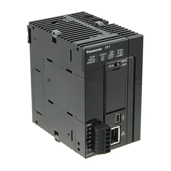
Names and Functions of Parts 2.1 CPU Unit (CPS4*/CPS3*) (13) (13) (12) (12) (11) (11) (10) (10) CPS41E/CPS31E/CPS31 CPS4E/CPS3E/CPS3 CPS41ES/CPS31ES/CPS31S Names and functions of parts (1) Operation monitor LEDs Body display Contents color Blue Turns on when the CPU unit power is ON. Green Turns on in the RUN mode. - Page 31 2.1 CPU Unit (CPS4*/CPS3*) (4) GT power supply terminal For our programmable display "GT series", either 5V DC output or 24V DC output can be used. (5) Power supply connector Connected with an external power supply (24V DC); When a power supply unit is used, do not connect this.
- Page 32 Names and Functions of Parts (Note) Do not apply an excessive force to the card cover when opening or closing it or when the cover is left open. Otherwise, the cover attachment part will be deformed to cause malfunction in the cover recognition switch mounted inside the product.
-
Page 33: Cpu Unit (Cps21)
2.2 CPU Unit (CPS21) 2.2 CPU Unit (CPS21) CPS21 Names and Functions of Parts (1) Operation monitor LEDs LED name Data to Display color Blue Lit when the CPU unit is turned ON. Lit when the CPU unit is in RUN mode. Lit when the forced /O function is Green executed. - Page 34 Names and Functions of Parts (6) COM0 port terminal Three-wire RS-232C port. (7) Unit connector Used for connecting an I/O unit or intelligent unit. An end unit is fitted when the unit is shipped. (8) USB port Used for connecting with a PC on which tool software is used. (9) Mode switch Switch position Operation mode...
-
Page 35: Power Supply Unit
2.3 Power Supply Unit 2.3 Power Supply Unit FP7-PSA1 FP7-PSA2 Names and functions of parts (1) POWER LED (blue) Turns on when power supply is turned on. (2) Power supply terminals Terminal block for power supply wiring. A solderless terminal for M3 can be used. (3) Earth terminals The unit should be grounded at a grounding resistance of 100 Ω... -
Page 36: Expansion Master Unit / Expansion Slave Unit
Names and Functions of Parts 2.4 Expansion Master Unit / Expansion Slave Unit Names and functions of parts (1) Operation monitor LEDs Body Contents display color Turns on when the total length of standard expansion cables for combined units is 9 m Green or less. - Page 37 2.4 Expansion Master Unit / Expansion Slave Unit (3) IN connector Used for connecting to the OUT connector of the expansion slave unit in the previous block with an exclusive expansion cable. (4) Power supply connector (AFP7EXPS only) Connected with an external power supply (24V DC); When a power supply unit is used, do not connect this.
- Page 38 Names and Functions of Parts 2-10...
-
Page 39: I/O Number Allocation
I/O Number Allocation... -
Page 40: Basics Of I/O Allocation
I/O Number Allocation 3.1 Basics of I/O Allocation 3.1.1 How to Count the I/O Numbers Counting and expression of the I/O numbers Since I/O numbers are handled in units of 16 points, they are expressed as a combination of a device type code and the lowest-digit of a decimal or hexadecimal number. - Page 41 3.1 Basics of I/O Allocation How to count I/O numbers for units that have both inputs and outputs In the case of a unit that has both inputs and outputs (e.g. mixed input/output units, intelligent units), input numbers and output numbers start with the same value. E.g.
-
Page 42: List Of Occupied I/O Points For Each Unit
I/O Number Allocation 3.1.3 List of Occupied I/O Points for Each Unit CPU Unit Occupied words Model No. or (occupied I/O points) Unit Type Function Input Output 2 words (32 points) 2 words (32 points) SCU built-in CPU Unit Common WX0-WX1 WY0-WY1... - Page 43 3.1 Basics of I/O Allocation I/O Unit Occupied words (occupied I/O points) Unit Type Model number Input Output Input unit 16 points AFP7X16DW 1 word (16 points) − Input unit 32 points AFP7X32D2 2 words (32 points) − Input unit 64 points AFP7X64D2 4 words (64 points) −...
-
Page 44: Optional Allocation Using Fpwin Gr7
I/O Number Allocation 3.2 Optional Allocation Using FPWIN GR7 3.2.1 Registration of a Unit to be Used and the Starting Word Number Allocation method The unit to be used and the starting I/O number are set in the following procedure. PROCEDURE 1. - Page 45 3.2 Optional Allocation Using FPWIN GR7 3. Confirm the installation position setting, and press the "OK" button. The CPU unit is registered in the I/O map. If the CPU unit is different, select "Tool" → "Convert PLC Type" from the menu bar and change the type. 4.
-
Page 46: Optional Settings In The "Unit Selection" Dialog Box
I/O Number Allocation 3.2.2 Optional Settings in the “Unit Selection” Dialog Box Input time constants Input time constants for an input unit or a mixed input/output unit can be changed as necessary. Select, and set for each unit, a desirable value from "No settings", 0.1, 0.5, 1.0, 5.0, 10.0, 20.0 or 70.0 ms. -
Page 47: Settings When Using Expansion Unit
3.2 Optional Allocation Using FPWIN GR7 3.2.3 Settings When Using Expansion Unit Make the settings according to the used configuration. Selection of Power supply unit and Expansion unit Setting item Description Common to Base and Power Select 24 V DC or a power supply unit according to the used configuration. Expansion supply unit AFPEXPM (Master, short distance): Select when the total length of expansion... -
Page 48: Mount Allocation Using Fpwin Gr7
I/O Number Allocation 3.3 Mount Allocation Using FPWIN GR7 3.3.1 Mount Registration of a Unit to be Used and the Starting Word Number What is mount registration? If all units to be used are physically at hand, you can connect FPWIN GR7 online to the FP7 CPU unit, read the actual mount status, and complete registration. -
Page 49: Changing The Starting Word Number
3.3 Mount Allocation Using FPWIN GR7 3.3.2 Changing the Starting Word Number When you want to change the starting word number following mount registration, please take the following procedure. Allocation method Changing the starting word number following mount registration should be performed in the following procedure. -
Page 50: I/O Map Registration
I/O Number Allocation 3.4 I/O Map Registration 3.4.1 I/O Map Registration What is I/O map registration? This refers to a status where I/O map information is registered in the CPU unit. To register an I/O map, the following methods are available. •... -
Page 51: Installation And Wiring
Installation and Wiring... -
Page 52: Installation
Installation and Wiring 4.1 Installation 4.1.1 Installation Environment and Space Installation environment Operating environment (Use the unit within the range of the general specifications when installing) • Ambient temperatures: 0 to +55 °C • Ambient humidity: 10 to 95%RH (at 25°C, no-condensing) •... - Page 53 4.1 Installation • Do not install the unit stacked up, horizontally or upside down. Doing so will prevent proper cooling of the unit and cause overheating inside. • Do not install the unit above devices which generate heat such as heaters, transformers or large scale resistors.
-
Page 54: Attaching Units
Installation and Wiring 4.1.2 Attaching Units • Attach unit attachment connectors on the side of each unit. • Make sure to connect an end unit to the right of the end unit. • After attaching units, attach the assembly to the DIN rail. (Note) When the CPU unit is CPS21, a power supply unit cannot be attached. - Page 55 4.1 Installation Lock the fixing hook. Unit removing procedure Release the fixing hook on the side of the unit. Slide the unit horizontally to remove it. Make sure to turn off power supply before attaching a unit. • Do not directly touch the connector part of the unit. •...
-
Page 56: Din Rail Attachment
Installation and Wiring 4.1.3 DIN Rail Attachment DIN rail attachment procedure Fully pull out the DIN rail attachment lever on the back of the unit. Fit the top of the unit attachment part into the DIN rail. While pressing down the unit attachment part onto the DIN rail, fit the bottom of the unit attachment part into the DIN rail. - Page 57 4.1 Installation DIN rail removal procedure Fully pull out the DIN rail attachment lever on the back of the unit. Pull the bottom of the unit forward. While pulling up the unit, remove it from the DIN rail.
-
Page 58: Wiring The Power Supply
Installation and Wiring 4.2 Wiring the Power Supply 4.2.1 Common Precautions To avoid the influence of noises • Use a low noise power supply. • The inherent noise resistance is sufficient for the noise superimposed on the power wires, however, the noise can be attenuated further by using the isolation transformer. -
Page 59: Wiring For Power Supply Units
4.2 Wiring the Power Supply 4.2.2 Wiring for Power Supply Units Terminal layout for power supply units Power supply voltage Confirm that the connected voltage is within the allowable range of the power supply. Model Rated input Allowable voltage Rated output Rated output number... -
Page 60: Wiring For The Power Supply Part Of The Cpu Unit
Installation and Wiring 4.2.3 Wiring for the Power Supply Part of the CPU Unit • When the CPU unit is used with 24V DC power supply, perform wiring for power supply as follows. • Use the power supply cables (Part No.:AFPG805) that come with the unit to connect the power supply. -
Page 61: Grounding
4.2 Wiring the Power Supply 4.2.5 Grounding • Ground the instrument to ensure sufficient noise suppression. • The point of grounding should be as close to the PLC as possible. The ground wire should be as short as possible. • Sharing the ground with another device may have an adverse effect. Therefore, be sure that grounding is dedicated. -
Page 62: Wiring Of Expansion Cable
Installation and Wiring 4.3 Wiring of Expansion Cable 4.3.1 Expansion Cable Type Use the expansion cable AFP7EXPC** (sold separately) for connecting the expansion master unit AFP7EXPM and expansion slave unit AFP7EXPS, or connecting the expansion slave units AFP7EXPS together. Model number Cable length AFP7EXPCR5 0.5 m... -
Page 63: Connecting Position And Direction Of Expansion Cables
4.3 Wiring of Expansion Cable 4.3.3 Connecting Position and Direction of Expansion Cables • The expansion cable is connected to the MIL connector of the expansion master unit AFP7EXPM and the MIL connector on the IN side of the expansion slave unit AFP7EXPS. •... -
Page 64: Safety Measures
Installation and Wiring 4.4 Safety Measures 4.4.1 Safety Circuit Precautions regarding system design • In certain applications, malfunction may occur for the following reasons: Power on timing differences between the PLC system and input/output or mechanical power apparatus. Response time lag when a momentary power drop occurs. Abnormality in the PLC unit, external power supply, or other devices. -
Page 65: Alarm Output
4.4 Safety Measures 4.4.3 Alarm Output • A power supply unit has an alarm output contact that can be used for releasing alarm signals to outside in the event of error. • The relay contact for alarm output is closed when power supply is ON. If the watchdog timer is operated due to a hardware error or a program error, the relay contact is turned into an open status. - Page 66 Installation and Wiring 4-16...
-
Page 67: Operation
Operation... -
Page 68: Before Powering On
Operation 5.1 Before Powering On 5.1.1 Check Points Once wiring has been completed, check the following points before powering on. Check Points Items Description Attaching Units • Does the product name match the device list during the design stage? •... -
Page 69: Procedures Before Starting Operation
5.1 Before Powering On 5.1.2 Procedures before Starting Operation Procedures following installation and wiring and before starting operation are as follows. 1. Powering on (1) Before powering on, carry out a check referring to "5.1.1 Check Points". (2) After powering on, check that the POWER LED (Blue) and PROG. LED (Green) are ON on the CPU unit. -
Page 70: Ram/Rom Operation
Operation 5.2 RAM/ROM Operation 5.2.1 Transmission of the Project Set the mode switch to "PROG". Check that the card operation switch is set to "ROM", and subsequently power on the unit. Switch setting conditions Switch Setting Mode switch PROG. Card operation switch ... -
Page 71: Operations Following Powering On
5.2 RAM/ROM Operation 5.2.2 Operations following Powering On When the unit is powered on, whether in the PROG. mode or in the RUN mode, the project is transmitted from ROM1 to RAM. Switch setting conditions Switch Setting Mode switch PROG. -
Page 72: Data Hold During Power Failure
Operation 5.2.3 Data Hold During Power Failure The FP7 CPU unit backs up most data into ROM (non-volatile memory). Data saved in ROM (non-volatile memory) • Project data (programs, configuration data, comments) • Hold type data in the operation memory •... -
Page 73: Backing Up The Project
5.3 Backing Up the Project 5.3 Backing Up the Project 5.3.1 Transmission from the Execution Memory RAM to the Backup Memory ROM2 In normal operation, you can save your project in the execution memory RAM/ROM1, and use the saved data. In order to prepare for unplanned rewriting, backup memory ROM2 is also installed. -
Page 74: Transmission From The Backup Memory Rom2 To The Execution Memory Ram/Rom1
Operation 5.3.2 Transmission from the Backup Memory ROM2 to the Execution Memory RAM/ROM1 It is possible to transmit the backup project saved in ROM2 to RAM/ROM1 to be used as an execution project. Switch setting conditions Switch Setting Mode switch PROG. -
Page 75: Sd Memory Card Operation
5.4 SD Memory Card Operation 5.4.1 Preparing SD Memory Cards Usable SD memory cards Use of Panasonic industrial SD memory cards is recommended. https://panasonic.net/cns/sdcard/industrial_sd/index.html (Note) An operation check has not been conducted for SD memory cards made by other manufacturers. -
Page 76: How To Insert An Sd Memory Card
Operation 5.4.2 How to Insert an SD Memory Card Take the following procedure to insert an SD memory card. Procedure Open the card cover on the surface of the CPU unit. Press in an SD memory card into the SD memory card slot until it locks. -
Page 77: Saving An Execution File For Sd Memory Card Operation
5.4 SD Memory Card Operation 5.4.3 Saving an Execution File for SD Memory Card Operation In order to enable operation by an SD memory card, it is necessary to convert the created project into an auto execution file. Take the following procedure. PROCEDURE 1. -
Page 78: Operation By An Sd Memory Card
Operation 5.4.4 Operation by an SD Memory Card Operation of a project saved in an SD memory card Insert an SD memory card, set the mode switch to "RUN", and set the card operation switch to "CARD" to enable the operation of a project saved in the card. ... - Page 79 5.4 SD Memory Card Operation Operations during SD Memory Card Operation If the following steps are taken, the unit runs in the "SD memory card operation" mode. Until the unit is powered off, it cannot be switched into RAM/ROM operation. Example 1: 1) Power on the unit while the card operation switch is set to "ROM".
-
Page 80: Transmission From An Sd Memory Card To The Execution Memory
Operation 5.4.5 Transmission from an SD Memory Card to the Execution Memory Insert an SD memory card, and set the mode switch to "COPY", in order to transmit a project saved in the SD memory card to ROM1 and write it in as an execution project. ... -
Page 81: Precautions Concerning Sd Memory Card Operation
5.4 SD Memory Card Operation When power is ON 1. Change to the PROG. mode. 2. Attach an SD memory card that houses the auto execution file "autoexec.fp7" and the comment file "comment.fp7" for a project to the CPU unit. 3. -
Page 82: Operation When Using Expansion Master Unit/Slave Unit
Operation 5.5 Operation When Using Expansion Master Unit/Slave Unit 5.5.1 Operation When Power Supply Turns ON/OFF Sequence of turning ON/OFF the power supply • The power supply should be turned on or off in the following sequence. Item Sequence When turning on Power supply for I/O device →... -
Page 83: Troubleshooting
Troubleshooting... -
Page 84: Self-Diagnosis Function
Troubleshooting 6.1 Self-Diagnosis Function 6.1.1 CPU Unit's Operation Monitor LED The CPU unit has a self-diagnostic function which identifies errors and stops operation if necessary. Indications concerning self-diagnosis are as follows. LED indications concerning self-diagnosis errors LED indications on the CPU unit Operation Description PROG... -
Page 85: What To Do If An Error Occurs
6.2 What to Do If an Error Occurs 6.2 What to Do If an Error Occurs 6.2.1 ERROR LED Flashes on the CPU Unit Condition A self-diagnostic error has occurred. Solution Confirm the status in the following procedure. PROCEDURE 1. -
Page 86: Prog Mode Does Not Change To Run
Troubleshooting 6.2.2 PROG Mode Does Not Change to RUN Condition: A syntax error or a self-diagnosis error that caused operation to stop has occurred. Solution: Confirm the status in the following procedure. PROCEDURE 1. Confirm that the ERROR or ALARM LED is not turned on. 2. -
Page 87: Power Led Does Not Turn On On The Power Supply Unit
6.2 What to Do If an Error Occurs 6.2.4 POWER LED Does Not Turn ON on the Power Supply Unit Condition: It is possible that sufficient power is not supplied. Solution: Confirm the status in the following procedure. PROCEDURE 1. -
Page 88: If Expected Output Is Not Available
Troubleshooting 6.2.6 If Expected Output Is Not Available Condition: Both software reasons (e.g. program, I/O allocation) and hardware reasons (e.g. wiring, power supply) are possible. Solution (check of the output side) Proceed from the check of the output side to the check of the input side. PROCEDURE 1. -
Page 89: Err Led Turns On On The Expansion Unit
6.2 What to Do If an Error Occurs terminal, there is probably an abnormality in the power supply or the input device. 4. Monitor the input status using the tool software FPWIN GR7. If the input monitored is off, there is probably an abnormality with the unit's input part. - Page 90 Troubleshooting KEY POINTS The expansion unit startup wait time can be set in the I/O map dialog box. • The settable range is 5 to 1800 seconds (30 minutes). The default is 5 seconds. A self-diagnostic error (Error code 6: Expansion unit power supply •...
-
Page 91: Maintenance And Inspection
Maintenance and Inspection... -
Page 92: Handling Of Backup Battery
Maintenance and Inspection 7.1 Handling of Backup Battery 7.1.1 Functions of Backup Battery When the calendar timer function is to be used, attach the separately sold backup battery. Never use batteries other than AFPX-BATT. It may lead to ignition and rupture of batteries. ... -
Page 93: Replacement Of Backup Battery
7.1 Handling of Backup Battery 7.1.2 Replacement of Backup Battery FP7 CPU unit's backup battery can be replaced while power is on. Replace the backup battery in the following procedure. Procedure Open the SD memory card cover on the surface of the CPU unit. Remove the battery connector. -
Page 94: Lifetime And Replacement Interval Of Backup Battery
Maintenance and Inspection Do not apply an excessive force to the card cover when opening or closing • it or when the cover is left open. Otherwise, the cover attachment part will be deformed to cause malfunction in the cover recognition switch mounted inside the product. -
Page 95: Inspection
7.2 Inspection 7.2 Inspection In order to use the unit in the optimal conditions, ensure routine/periodic inspection. Inspection items Inspection Items Description Criteria Related Pages Power Supply Unit Check POWER LED on power Normal if on p.2-7 supply unit Body of the Power Supply Unit Periodic replacement p.2-7... - Page 96 Maintenance and Inspection...
-
Page 97: Specifications
Specifications... -
Page 98: Cpu Unit Specifications
Specifications 8.1 CPU Unit Specifications 8.1.1 General Specifications Items Description Rated voltage 24V DC Operating voltage range 20.4 to 28.8V DC (Note 1) When the CPU unit only (DC) is used 4 ms (20.4 V is used) , 7 ms (24 V is used) , 10 ms (28.8 V is used) Momentary power off time (Note 2) Allowable maximum current... - Page 99 8.1 CPU Unit Specifications Weight Product name Model number Weight 100 to 240V AC, 24W AFP7PSA1 Approx. 240g Power Supply Unit 100 to 240V AC, 3W AFP7PSA2 Approx. 290g CPU Unit Including an end unit AFP7CPS* Approx. 220g AFP7CCS1, AFP7CCS2, AFP7CCM1, Approx.
-
Page 100: Performance Specifications
Specifications 8.1.2 Performance Specifications Items Description Program method Relay symbol method Control method Cyclic operation method Basic configuration Max. 1,024 points (64 points x 16 slots) Controllable When the PHLS remote I/O points Max. 16,128 points (1,008 points x 16 slots) I/O system is used Execution project saving memory (RAM and ROM1) : Non-volatile Built-in memory... - Page 101 8.1 CPU Unit Specifications Items Description Master control relay (MCR) No limits (no numbers) Labels (JMP, LOOP) Max. 65,535 points per PB Differential points (DF, DFI) Depending on the program capacity No. of step ladders No restriction No. of subroutines Max.
-
Page 102: Cpu Unit Communication Specifications
Specifications 8.1.3 CPU Unit Communication Specifications USB port (for tool software) Items Description Standard USB2.0 FULL SPEED Communication function MEWTOCOL-COM (slave), MEWTOCOL7-COM (slave) (Note) The USB port is insulated from the internal circuit. COM0 port Items Description Interface 3-wire 1-channel RS232C Transmission distance 15 m... - Page 103 8.1 CPU Unit Specifications LAN port (CPS41E/ CPS31E) Items Description Interface 100BASE-TX / 10BASE-T Baud rate 100 Mbps, 10 Mbps auto-negotiation (Note 1) Cable total length 100 m (500 m when using a repeater) Communication cable UTP (Category 5) No.
-
Page 104: Operation Memory Area
Specifications 8.1.4 Operation Memory Area Name Usable devices and ranges Functions External input 8,192 points (X0 to X511F) (Note 1) Turns on or off based on external input. External 8,192 points (Y0 to Y511F) (Note 1) Externally outputs on or off state. output Relay which turns on or off only within Internal relay... - Page 105 8.1 CPU Unit Specifications Name Usable devices and ranges Functions 15 double words (I0 to IE) Register can be used as an address of Index register (with a switching function) memory area and constants modifier. Timer set value 4,096 double words Data memory for storing timer target area (TS0 to TS4095) (Note 2)
-
Page 106: List Of System Relays
Specifications 8.1.5 List of System Relays Device Name Description number Turns on when a self-diagnosis error occurs. Self-diagnosis error Self-diagnostic error flag codes are saved in the system data register SD0. Turns on when a unit alarm is detected. The slot number of the unit Unit alarm occurrence where an alarm has occurred is saved in the system data register SD1. - Page 107 8.1 CPU Unit Specifications Constant scan error Turns on if scan time exceeds the setting during constant scan. It flag also turns on if '0' is set in FP7 configuration. Device Name Description number SR10 Normally-on relay Is normally on. SR11 Normally-off relay Is normally off.
- Page 108 Specifications Device Name Description number ON: RUN mode SR20 CPU operation modes OFF: PROG. mode ON: SD memory card SR21 Operation program memory OFF: ROM Turns on if an error is detected in calendar timer data when the SR22 RTC data error unit is powered on.
- Page 109 8.1 CPU Unit Specifications Device Name Description number ON: Cover open SR30 SD slot cover status flag OFF: Cover closed SD memory card attachment ON: With an SD memory card SR31 flag OFF: Without an SD memory card SD memory card recognition ON: Completed recognition of an SD memory card SR32 completed flag...
- Page 110 Specifications WS10 (Logging trace control relays: For LOG0) Device Name Description number Turns on when the logging trace is performed. Other relays in SR100 Logging trace execution LOGn turns off while this relay turns on. Storing data in the buffer memory is executed while this relay turns on. Turns on when writing files to a SD card becomes enabled SR101 SD card logging execution...
- Page 111 8.1 CPU Unit Specifications WS11 - WS25 (Logging trace control relays: For LOG1 - LOG15) Device Name Description number SR110 Logging trace control relay -SR119 For LOG1 SR120 Logging trace control relay -SR129 For LOG2 SR130 Logging trace control relay -SR139 For LOG3 SR140...
- Page 112 Specifications WS100 - WS149 Device Name Description number Can monitor program blocks that are being started up. SR1000 to SR1499 are allocated to 500 PBs. Device PB number number SR1000 PB 000 SR1001 PB 001 SR1002 PB 002 SR1000 Program block ----- ----- to SR1499...
-
Page 113: List Of System Data Registers
8.1 CPU Unit Specifications 8.1.6 List of System Data Registers SD0 – SD39 Device Name Description number Self-diagnostic error code Stores the error code when a self-diagnosis error occurred. Saves the slot number of the unit where an alarm has Alarm Occurrence Unit Slot No. - Page 114 Specifications SD50 - SD85 Device Name Description number SD50 Calendar timer (year) Saves year, month, day, hour, minute, second and day-of-the- SD51 Calendar timer (month) week data of the calendar timer as 16-bit binary data. The SD52 Calendar timer (day) built-in calendar timer will operate correctly through the year SD53 Calendar timer (hour)
- Page 115 8.1 CPU Unit Specifications SD100 - SD115 and SD120 - SD125 (For logging trace control) Device Name Description number SD100 Buffer free space for LOG0 SD101 Buffer free space for LOG1 SD102 Buffer free space for LOG2 SD103 Buffer free space for LOG3 SD104 Buffer free space for LOG4 SD105...
-
Page 116: Error/Warning Codes Tables
Specifications 8.1.7 Error/Warning Codes Tables Error codes 1 to 6 Code Name Operation Error contents and steps to take CPU hardware error 1 Stop There may be a hardware problem. Please contact your dealer. CPU hardware error 2 Stop Error in the I/O bus part is probable, such that the end unit has I/O bus power supply not been attached. - Page 117 8.1 CPU Unit Specifications Error codes 20 to 27 Code Name Operation Error contents and steps to take Stop A program with a syntax error has been written. Switch to the Syntax error Auto clear PROG. mode and correct the error. The same relay is used multiple times in OT instruction, etc.
- Page 118 Specifications Error codes 40 to 55 Code Name Operation Error contents and steps to take Copy failure Stop The card cover is open and the copy process cannot be Cover open Auto clear executed. Close the cover. Copy failure Stop Copying cannot be executed because there is no SD No SD card Auto clear...
- Page 119 8.1 CPU Unit Specifications Error codes 80 to 106 Code Name Operation Error contents and steps to take An alarm has occurred in an attached unit. Check the Select Unit alarm occurrence status of the unit in the slot number saved in the (Default stop) system data register SD1.
- Page 120 Specifications Error codes 120 to 127, 1000 to 2999 Code Name Operation Error contents and steps to take An error has been detected in clock data of the RTC data error Continue calendar timer. Power supply unit It is alarmed that the power supply unit is close to its Continue lifetime warning lifetime.
- Page 121 8.1 CPU Unit Specifications Error codes for SCU unit and built-in SCU unit Error code Name 0x7001 Mode setting/changing error 0x7002 Parameter setting error 0x7003 Sent data amount error 0x7005 Communication cassette verification error 0x7006 PLC link registration exceeded 0x7007 Duplicated PLC link area block number 0x70E0 Configuration data version error...
- Page 122 Specifications Error codes for built-in ET-LAN unit Error code Name 8001H Local node address setting error 8002H Subnet mask setting error 8003H Default router (gateway) IP address setting error 8004H DNS address setting error 8009H Initial processing error 8014H Address setting error 8015H Operation mode setting error Warning codes for built-in ET-LAN unit...
-
Page 123: Power Supply Unit Specifications
8.2 Power Supply Unit Specifications 8.2 Power Supply Unit Specifications 8.2.1 General Specifications Items Description Operating ambient 0 to +55°C temperature Operating ambient 10 to 95%RH (at 25°C, no-condensing) humidity Storage ambient -40 to +70°C temperature Storage ambient humidity 10 to 95%RH (at 25°C, no-condensing) All the AC inputs ←→... -
Page 124: Performance Specifications
Specifications 8.2.2 Performance Specifications Items Description Model number AFP7PSA1 AFP7PSA2 Rated input voltage 100 to 240V AC Input voltage amplitude range 85 to 264V AC Rated frequency 50 / 60 Hz Frequency range 47 to 63 Hz Input Phases Single-phase Input current 0.75A or less 1.25A or less... -
Page 125: Dimensions
8.3 Dimensions 8.3 Dimensions 8.3.1 Power Supply Unit (12.8) 8-29... -
Page 126: Cpu Unit (Cps4*/Cps3*)
Specifications 8.3.2 CPU Unit (CPS4*/CPS3*) (10) 8.3.3 CPU Unit (CPS21) (10) 8-30... -
Page 127: Terminal Block Type Unit (1)
8.3 Dimensions 8.3.4 Terminal Block Type Unit (1) Applicable units: Digital I/O unit (16-point), Analog input unit, Analog output unit (18) 8.3.5 Terminal Block Type Unit (2) Applicable units: Thermocouple multi-analog input unit, RTD input unit (10) 8-31... -
Page 128: Connector Type Unit
Specifications 8.3.6 Connector Type Unit Digital I/O unit (32-point), High-speed counter unit (2-ch), Pulse output unit (2-axis), Positioning unit (2-axis), Expansion master unit Digital I/O unit (64-point), High-speed counter unit (4-ch), Pulse output unit (4-axis), Positioning unit (4-axis) ,Expansion slave unit (19) (Note) The expansion slave unit is equipped with a power supply connector. -
Page 129: Serial Communication Unit
8.3 Dimensions 8.3.7 Serial Communication Unit The drawing below shows the state that two communication cassettes are attached. (10) 8.3.8 PHLS Master Unit (12.8) 8-33... -
Page 130: End Unit
Specifications 8.3.9 End Unit 14.5 8-34... -
Page 131: Figures Of Unit Combination
8.3 Dimensions 8.3.10 Figures of Unit Combination When the power supply unit AFP7PSA1 is used FP7 system full width = Power supply unit AFP7PSA1 + CPU unit + n devices (input/output units and intelligent units) + End unit = 50mm + 40mm + (n x 28mm) + 14.5mm = 104.5mm + (n x 28mm) ... - Page 132 Specifications When no power supply unit is used FP7 system full width = CPU unit + n devices (input/output units and intelligent units) + End unit = 40mm + (n x 28mm) + 14.5mm = 54.5mm + (n x 28mm) Note) The size of the CPU unit is 6mm shorter when using CPS21.
- Page 133 Record of changes Manual No. Date Record of Changes WUME-FP7CPUH-01 Mar.2013 1st Edition WUME-FP7CPUH-02 Jun.2013 2nd Edition - Added new models CPU units CPS3E and CPS3 I/O units Y32P, Y64P and XY64D2P - Error correction WUME-FP7CPUH-03 Oct.2013 3rd Edition - Added new models High-speed counter unit WUME-FP7CPUH-04 Dec.2013 4th Edition...
- Page 134 Manual No. Date Record of Changes WUME-FP7CPUH-06 Jun.2015 6th Edition - Added new models CPU unit: AFP7CPS21 WUME-FP7CPUH-07 Nov.2019 7th Edition - Added a note about the SD card cover - Added error/warning codes - Corrected mistakes...
- Page 136 ■ Overseas Sales Division (Head Office): 2431-1 Ushiyama-cho, Kasugai-shi, Aichi, 486-0901, Japan ■ Telephone: +81-568-33-7861 ■ Facsimile: +81-568-33-8591 panasonic.net/id/pidsx/global About our sale network, please visit our website. © Panasonic Industrial Devices SUNX Co., Ltd. 2019 November, 2019 PRINTED IN JAPAN WUME-FP7CPUH-07...
Need help?
Do you have a question about the FP7 Series and is the answer not in the manual?
Questions and answers