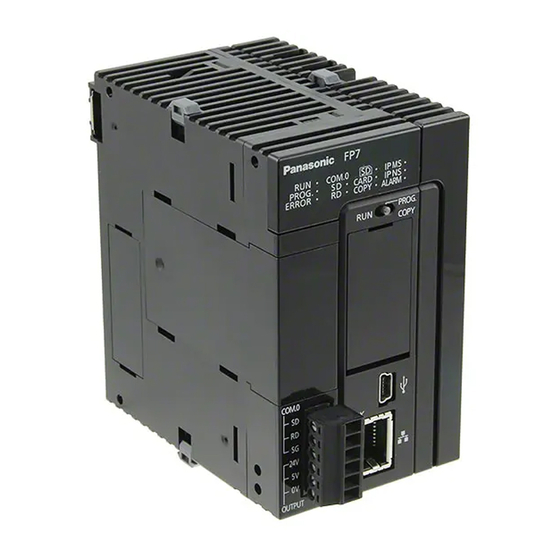
Panasonic FP7 Series User Manual
Cpu unit
Hide thumbs
Also See for FP7 Series:
- Command reference manual (1222 pages) ,
- User manual (275 pages) ,
- Additional functions manual (45 pages)


Need help?
Do you have a question about the FP7 Series and is the answer not in the manual?
Questions and answers