Table of Contents
Advertisement
Quick Links
Advertisement
Table of Contents

Related Manuals for Schaeffler SmartCheck


Summary of Contents for Schaeffler SmartCheck
- Page 1 Schaeffler SmartCheck User manual...
- Page 2 Full licence conditions for the respective libraries can be found in the software's program directory. Version 1.16.0 Translation of the original user guide. © 19/12/2019 - Schaeffler Monitoring Services GmbH...
-
Page 3: Table Of Contents
Contents Contents General ..............................4 Safety inform ation ......................................4 Hazard sym bols and signal w ords ......................................4 About this guide ......................................5 Product description ..............................6 Intended use ......................................6 Modifications by the user ......................................7 Technical data ...................................... -
Page 4: General
General safety information Schaeffler SmartCheck is integrated in a machine as a system for permanent machine monitoring. The system must be installed in the machine, connected to machine components and operated in the machine within the specifications set out in this guide (see Technical data ). -
Page 5: About This Guide
To operate the Schaeffler SmartCheck device, you will also need the supplied Schaeffler SmartUtility Light software. This is also dealt with in a separate manual. You also have the option of purchasing the Schaeffler SmartUtility software, which features enhanced functionality. -
Page 6: Product Description
These signals can be used as command variables for a dependent signal analysis, e.g. to initiate time or event-controlled measurement tasks. The Schaeffler SmartCheck device can be used to cover a wide range of applications; the SmartCheck device can be configured to meet your own requirements using the integrated web application and Schaeffler SmartWeb software. -
Page 7: Modifications By The User
Product description 2.2 Modifications by the user The user must not make any modifications to the Schaeffler SmartCheck device. The user may only make settings on the device itself or via the Schaeffler SmartWeb, Schaeffler SmartUtility Light or Schaeffler SmartUtility software. -
Page 8: Scope Of Delivery
The standard scope of delivery for the Schaeffler SmartCheck device does not include any cables for connecting the device. Optional accessories An extensive range of optional accessories for the Schaeffler SmartCheck is available from Schaeffler Monitoring Services GmbH: · SmartUtility software with user documentation on CD-ROM; this software features enhanced functionality compared with the SmartUtility Light software ·... -
Page 9: Installation
Installation site To install the SmartCheck device, select a site with optimum vibration transfer. To monitor a bearing for example, this would be near the roller bearing you wish to monitor and radial to the axis of rotation. It is recommended to consult a vibration expert for this step to ensure optimum condition monitoring. -
Page 10: Dimensions
Basic dimensions from the side The side view shows the angled surface of the SmartCheck device; you can also see how far the connections protrude and how the sensor area is dimensioned. Basic dimensions in cross-section The open cross-section affords a view into the mounting aperture of the SmartCheck device and shows the dimensions of the fixing screw and sensor area. -
Page 11: Installing The Device Directly On A Component
You can also use an optional screw locking compound (e.g. Loctite threadlock) to ensure the installation is permanent. 6. Align the sensor area of the SmartCheck device on the installation surface and hand-tighten the fixing screw using an offset screwdriver. Ensure that SmartCheck is sitting flat on the surface to ensure optimum vibration transfer. -
Page 12: Installing The Device On A Sensor Mounting Plate
3.4 Installing the device on a sensor mounting plate If the SmartCheck device cannot be screwed directly onto a machine or component, you can bond an M6 sensor mounting plate onto the installation surface and then screw the device to the mounting plate. The M6 sensor mounting plate is available as an optional accessory from Schaeffler Monitoring Services GmbH. -
Page 13: Closing The Mounting Aperture
Installation 6. Use a torque wrench to tighten and secure the connection to a tightening torque from 5 to 10 Nm. 9. Check that Schaeffler SmartCheck is seated securely. 10. Close the mounting aperture on the device by inserting the plug bearing the logo until it snaps in place. -
Page 14: Set-Up
· Set up a PC/Ethernet connection · Connect the power supply To set up and operate the SmartCheck device, you will need the following connection cables, which are not included in the standard scope of delivery: · Input/output cables ·... -
Page 15: Connection Overview
4.1 Connection overview In the following graphic you will find: · A detailed circuit diagram with information concerning all of the connection options for the SmartCheck device, i.e. concerning the inputs and outputs , communication via Ethernet and the power supply ·... -
Page 16: Connection Details
* Colour specifications apply for standard cables from the optional accessories for the Schaeffler SmartCheck device. Connection 2: Ethernet plug The Ethernet plug, which you can use to connect the SmartCheck device to your computer and to the Internet/Intranet, is located at the top right. - Page 17 Connection 3: Power supply plug The power supply plug on the SmartCheck device, including the supply to the real time clock (RTC), is below. This connection can also be used for RS485, e.g. to connect Schaeffler SmartCheck to your machine controller or to other SmartCheck devices.
-
Page 18: Connecting Inputs And Outputs
4.3 Connecting inputs and outputs You have the option of using the SmartCheck device with two analogue inputs, one digital input, one analogue output or one digital output. To do this, you will need to create a cable connection and connect your external... - Page 19 Set-up You must also configure the digital input using the integrated Schaeffler SmartWeb software. To do this, open the Configuration > Input configurations > Digital input field in the SmartWeb software. You can configure the digital input using the Edit button as follows, for example: Details of the possible settings can be found in the Schaeffler SmartWeb user documentation.
-
Page 20: Connection Configuration: Analogue Speed Signal
SmartCheck device. Details of both options can be found in the sections below. Analogue speed signal from motor controller This is how you connect a motor controller to the Schaeffler SmartCheck analogue input; in our example, the motor controller delivers a speed signal of 0-3000 rpm with 0-10 V: You must also configure the analogue input using the integrated Schaeffler SmartWeb software. - Page 21 Analogue speed signal from programmable logic controller (PLC) This is how you connect a PLC, e.g. a machine controller, to the analogue input of Schaeffler SmartCheck; in our example, the PLC delivers an analogue speed signal of 0-3000 rpm with 4-20 mA: The analogue input of the SmartCheck device has a 500 ohm resistance when used as a current input.
-
Page 22: Connection Configuration: Analogue Output Signal
4.3.3 Connection configuration: Analogue output signal This is how you connect a PLC, e.g. a machine controller, to the Schaeffler SmartCheck analogue output. In our example, the SmartCheck device delivers an analogue output signal to a PLC with 4-20 mA. -
Page 23: Connection Configuration: Digital Output Signal
Set-up 4.3.4 Connection configuration: Digital output signal You can supply a digital output signal to a relay or a PLC via the Schaeffler SmartCheck digital output. Details of both options can be found in the sections below. Digital output signal to relay For this option, the SmartCheck device provides a digital open-collector output that can switch a relay against positive. - Page 24 Digital output signal to PLC With this option, the SmartCheck device supplies a digital output signal to a PLC. The line should be connected to a suitable pull-up resistor. You must also create the digital output using the integrated SmartWeb web application. To do this, open the Configuration >...
-
Page 25: Connecting Pc/Ethernet
In order to view measurement data from the SmartCheck device, download data or manage settings for the SmartCheck, you must connect the device to your PC via Ethernet. You can then call up and manage the SmartCheck in a browser using the dedicated SmartWeb software. -
Page 26: Connecting The Power Supply
The machine to be monitored is in a normal operating state You can supply power to the SmartCheck device using either the power plug (power) or the Ethernet plug (Power over Ethernet). Relevant details can be found in the following sections. - Page 27 5. Connect the cable to the network switch. Details on the assignment of the cable can be found under Connection details An illustration of all the connection options for the SmartCheck device can be found in the Connection overview section.
-
Page 28: Connecting Multiple Devices
4.6 Connecting multiple devices If you wish to install multiple SmartCheck devices, you can use M12 Y-splitters to connect the devices to the power supply and significantly reduce the length of cable required. The following illustrations provide an overview of the wiring for two basic applications: ·... - Page 29 Set-up Power supply connection for SmartCheck and RTC...
-
Page 30: Operation And Controls
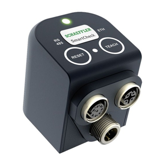
Control elements All controls on the SmartCheck device are located on the top of the device. Here you will find two buttons and a total of four LEDs — the functions of these LEDs are described in more detail in the following sections. - Page 31 Communication via RS485 is not currently supported. ETH LED The ETH LED is located to the right of the fixing screw cover (item 3): This LED lights up blue when the SmartCheck device is connected to the Ethernet network. It flashes when data is being exchanged.
-
Page 32: Reset And Teach Buttons
Deactivating the key lock If you want to operate the keys on the SmartCheck device, you must first deactivate the key lock. Press the Reset key and then press the Teach key within 2 seconds. The LED between the keys (item 4) flashes to confirm. - Page 33 Operation and controls You can restore the Schaeffler SmartCheck device to its factory settings using both buttons. To do this, the device must be fully started and be ready to measure (observe the status LED after switching on ). Then press the Reset button and the Teach button together at the same time and hold for longer than 10 seconds.
-
Page 34: Further Information
Viewing the signal in the browser for the first time Once the Schaeffler SmartCheck vibration monitoring system has started up and is in measuring mode, you can view the measurement data using the Schaeffler SmartWeb software on your PC. This allows you to check whether a valid vibration or temperature signal is being received, whether you have connected and configured the inputs correctly and whether the SmartCheck device is operating properly. - Page 35 · For example, select the Vibration sensor input from the menu on the left. If you have connected the SmartCheck device correctly, you will see the signals of the vibration sensor/the selected signal input in the Live view area. Live view in the Schaeffler SmartWeb software...
-
Page 36: Maintenance And Repair
Maintenance and repair The SmartCheck device is a closed, embedded system and as such is essentially maintenance free. Should you detect a fault with the SmartCheck device, please contact our Support team. Cleaning You can clean the outside of the device if necessary. -
Page 37: Decommissioning And Disposal
Decommissioning and disposal Decommissioning and disposal Decommissioning If the SmartCheck can no longer be operated safely, the device must be decommissioned and secured against inadvertent operation. The device can no longer be operated safely if it: · Exhibits visible signs of damage ·... -
Page 38: Manufacturer/Support
Tel.: +49 (0) 2407 9149 99 Email: support.is@schaeffler.com We provide support services for the Schaeffler SmartCheck device and related software products. A detailed description of the type and scope of the support services we provide can be found online at... -
Page 39: Appendix
Appendix 10 Appendix EC conformity declaration...
Need help?
Do you have a question about the SmartCheck and is the answer not in the manual?
Questions and answers