Table of Contents
Advertisement
Quick Links
Advertisement
Table of Contents

Subscribe to Our Youtube Channel
Related Manuals for AGM Global Vision VICTRIX


Summary of Contents for AGM Global Vision VICTRIX
- Page 1 VICTRIX THERMAL IMAGING CLIP-ON SYSTEM USER MANUAL...
- Page 2 EXPORT INFORMATION Buyer acknowledges that all products supplied by AGM Global Vision are subject to U.S. export control laws, including, but not limited to, the Export Administration Regulations, the International Economic Emergency Powers Act, and various U.S. embargoes and sanctions. AGM Global Vision products may not be exported, re-exported, or transferred contrary to U.S.
-
Page 3: Table Of Contents
2.1 Installation and Mounting 2.2 Controls and Display Indicators 2.3 Operating Procedures 3. MAINTENANCE INSTRUCTIONS 3.1 Operator Troubleshooting 3.2 Maintenance 4. WARRANTY INFORMATION 4.1 Warranty Information and Registration 5. SPECIFICATIONS 5.1 Specifications APPENDIX A. Spare Parts List Victrix USER MANUAL... -
Page 4: Safety Summary
If you are allergic to latex, learn which products contain it and strictly avoid exposure to those products. WARNING: Recommends that you use an eyecup on the eyepiece of the day scope, to allow for maximum comfort, space, and to remain undetected. AGM Global Vision... - Page 5 The optical axes of the Victrix and day scope should be aligned. The distance between the axes should not exceed 3 mm. If the difference in the axis heights of the Victrix and day scope above the weapon rail exceeds 3 mm, you will need to replace the day scope mounting rings or monoblock.
-
Page 6: General Information
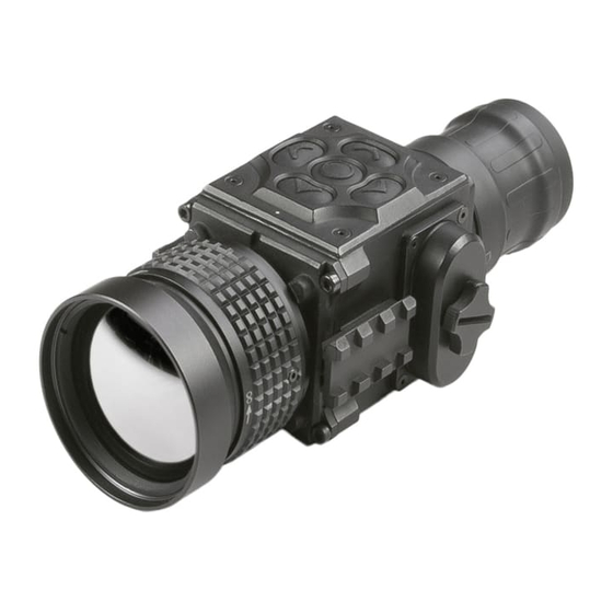
FIGURE 1-1. VICTRIX THERMAL IMAGING CLIP-ON SYSTEM The Victrix is a thermal sensitive device. It can sense differences in heat emitted by objects in its field of view, and converts the received temperature pattern into a viewable image that represents the scene in black and white or a color pattern, depending on the selected image palette. - Page 7 The quick-release mount of the Victrix fits any Picatinny, MIL-STD-1913, or Weaver weapon rail. The mount’s lever-cam clamping device ensures quick, easy and reliable mounting and removal. The Victrix is shown in Figure 1-2. The ITEM NO. column of Table 1-1 indicates the number used to identify items in Figure 1-2.
-
Page 8: Standard Components
1.2 STANDARD COMPONENTS The Victrix standard components are shown in Figure 1-3 and listed in Table 1-2. The ITEM NO. column indicates the number used to identify items in Figure 1-3. FIGURE 1-3. STANDARD COMPONENTS TABLE 1-2. STANDARD COMPONENTS ITEM NO. -
Page 9: Optional Equipment
ITEM NO. DESCRIPTION PART NO. Front Scope Mount 1 A mounting system used to install the Victrix on the lenses of 6106SM11 specified day scopes. Includes a clamp with inserts that will fit 25.4 and 30 mm diameters. Front Scope Mount 2... -
Page 10: Key Features
External Wi-Fi module (optional) • Fits any Picatinny, MIL-STD-1913, and Weaver rail with an adjustable quick-release mount • Serviceability under severe conditions • Filled with dry nitrogen to prevent internal fogging • Waterproof • Limited 3-year warranty AGM Global Vision... -
Page 11: Operating Instructions
When the device is on a battery charge level is displayed on the status bar (Figure 2-2). FIGURE 2-2. BATTERY STATUS BAR WARNING: Do not use rechargeable batteries since their use causes inaccurate battery level indication and possible disconnection during operation. Victrix USER MANUAL... - Page 12 The optical axes of the Victrix and day scope should be aligned. The distance between the axes should not exceed 3 mm. If the difference in the axis heights of the Victrix and day scope above the weapon rail exceeds 3 mm, you will need to replace the day scope mounting rings or monoblock.
- Page 13 Figure 2-4) and unlocking the cam lever (C). 4. Install the Victrix on the Picatinny/Weaver rail in front of the day scope so that the stop (E, see Figure 2-2) slides into one of the rail’s transverse slot. The light suppressor should cover the day scope’s objective lens.
- Page 14 3. With the nut (B) loosened, place the insert (C) into the FSM’s clamp (A). 4. Screw the FSM into the Victrix’s output lens thread. 5. With the nut (B) loosened, slide the Victrix with the FSM onto the lens of the day scope as far as it goes.
- Page 15 1. Decide on desirable position of the nut and estimate the angle through which the FSM should be turned CW (see Figure 2-8). 2. Remove the FSM from the Victrix. 3. Using a screwdriver, remove the M2×2.5 screws (F, see Figure 2-7) and then unscrew the ring (E).
- Page 16 Victrix. Connect the video cable plug (C) to the Victrix S620 universal connector. Use the video cable plug (B) to connect an external power source (6 VDC / 600 mA) to the Victrix. Connect the video cable plug (C) to the Victrix S620 universal connector.
-
Page 17: Controls And Display Indicators
DO NOT force the equipment controls past their stopping points. The Victrix controls are shown in Figures 2-12 and 2-14, and are defined in Tables 2-1 and 2-2. The ITEM NO. columns indicate the numbers used to identify items in the figures. - Page 18 While imaging the flat-field source, the camera updates the offset correction coefficients, resulting in a more uniform image after the process is complete. The Victrix allows the user to manually trigger or interrupt scheduled NUC function.
- Page 19 Select one of the sharpness aside (Normal/Smooth/Sharp) with a short press of Up / Down. STADIAMETRIC RANGEFINDER Victrix clip-on is equipped with a stadiametric rangefinder which allows the user to estimate approximate distance to an object of known size. FIGURE 2-9. STADIAMETRIC RANGEFINDER You will see on the display: measurement bars, icons of three reference objects and respective distances for the three objects.
- Page 20 Press the Up / Down buttons to change LED brightness from 0, 1, 2. UNIT Press Up/Down to select units of measurement from Yards and Meters. DEFECTIVE PIXEL REPAIR Press Up/Down buttons then close lens cover to repair defective pixel. Defective pixels are found by software algorithm. AGM Global Vision...
- Page 21 The final accuracy depends on customer riflescope, its parallax and shooting distance. The Victrix ensures the shooting precision tolerance within 3 to 7 cm at 100 m. To achieve better accuracy, use Alignment Correction option in the main menu (last icon).
- Page 22 1) Aim your day scope to the middle of target and shoot. This action will test the control of day scope accuracy. 2) Mount the Victrix on the riflescope. Aim to the target and shoot again. 3) Measure horizontal (x) and vertical distance (y) between shoot and aiming position from step 2.
-
Page 23: Operating Procedures
8. Turn on the day scope’s reticle illumination and adjust the reticle brightness. 9. Adjust the focus of Victrix by turning the focus ring (CW for far focus, CCW for near focus). 10. Using the QUICK MENU, configure the Victrix to adapt it to your situation. - Page 24 DO NOT leave the equipment activated when not in use. 2.3.2 VICTRIX SHUT-DOWN NOTE: Shut down the Victrix to properly to avoid losing unsaved settings and data. Shutdown the Victrix as follows: 1. Turn off the Victrix. 2. Replace the cap on the objective lens.
-
Page 25: Maintenance Instructions
Table 3-1 lists the common malfunctions that may be found during the operation or maintenance of the Victrix. Perform the tests/inspections and corrective actions in the order listed. This table does not list all of the malfunctions that may occur with your device, or all of the tests and corrective actions that may be necessary. -
Page 26: Maintenance
Maintenance instructions covered elsewhere in this manual (troubleshooting, etc.) are not repeated in this section. CAUTION: The Victrix is a precision electro-optical instrument and must be handled carefully at all times to prevent damage. CAUTION: DO NOT dismantle the equipment. -
Page 27: Warranty Information
Customer. AGM Global Vision’s liability hereunder for damages, regardless of the form or action, shall not exceed the fees or other charges paid to AGM Global Vision by the customer or customer’s dealer. AGM Global Vision shall not, in any event, be liable for special,... - Page 28 AGM Global Vision’s service center at the address listed above. All merchandise must be fully insured with the correct postage; AGM Global Vision will not be responsible for improper postage or merchandise that becomes lost or damaged during shipment. When sending product back, please clearly write the RMA# on the outside of the shipping box.
-
Page 29: Specifications
• Universal S620 connector Interfacing (Power In, Analog Video In/Out, Wi-Fi Attachment, HD Recorder, Extended Battery Pack) TABLE 5-2. OPTICAL DATA ITEM VICTRIX TC38 VICTRIX TC50 - ang. X degrees Field of View - ang. Y degrees Objective Focal Length... - Page 30 External Power Supply up to 8 hr.) or 6V/600 mA power supply via S620 universal connector TABLE 5-4. MECHANICAL DATA ITEM VICTRIX TC38 VICTRIX TC50 Weapon Mount Type Picatinny MIL-STD-1913 and Weaver Rails 181 × 84 × 64 mm 190 × 84 × 64 mm Overall Dimensions (7.1 ×...
- Page 31 Meopta Artemis 3000 4-12x40 50,0 Schmidt & Bender 10x42 56,0 Zeiss 2.5 10x50 Front Scope 57,0 Schmidt & Bender 3-12x50 Mount 4 Leupold 4.4-14x50; 58,7 Leupold VX-III 3.5-10x50 Zeiss 3-12x56; Front Scope 62,0 Swarovski 2.5-10x56; Mount 5 Kahles CSX 3-12x56 Victrix USER MANUAL...
-
Page 32: Appendix
The PART NO. column indicates the primary number used by the manufacturer to identify an item, which controls the design and characteristics of that item by means of its engineering drawings, specifications, standards, and inspection requirements. FIGURE A-1. VICTRIX SPARE PARTS LIST AGM Global Vision... - Page 33 TABLE A-1. VICTRIX SPARE PARTS LIST ITEM DESCRIPTION PART NO. Mount AGMANQRM Riser AGMANRSR Objective Lens Cap 50mm GOL50OBLCP Objective Lens Cap 38mm GOL38OBLCP Objective Lens Assembly 50mm GOL50OBLAS Objective Lens Assembly 38mm GOL38OBLAS Battery Cap AGMTIDBCP Connectors Cap AGMTIDCNCP...
- Page 34 NOTE AGM Global Vision...
- Page 35 NOTE Victrix USER MANUAL...
- Page 36 AGM Global Vision MAIN OFFICE 173 West Main Street PO Box 962 Springerville, AZ 85938 Tel. +1.928.333.4300 Fax +1.480.393.4882 info@agmglobalvision.com www.agmglobalvision.com EUROPEAN OFFICE Andrey Lyapchev #7 Sofia, P.C. 1756 Bulgaria Tel. +44.292.255.0509 info@agmglobalvision.eu www.agmglobalvision.eu AGMglobalvision.com...
Need help?
Do you have a question about the VICTRIX and is the answer not in the manual?
Questions and answers